
Subscribe to Our Youtube Channel
Related Manuals for Coby CSMP95


Summary of Contents for Coby CSMP95
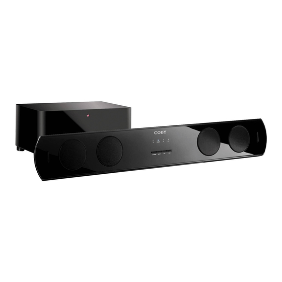
- Page 1 CSMP95 2.4GHz DIGITAL WIRELESS SOUNDBAR SYSTEM OWNER`S MANUAL Read this manual carefully to get the best performance from 2.1 System...
-
Page 2: Warnings And Precautions
WARNINGS AND PRECAUTIONS WARNING: To reduce the risk of fire or electric shock, do not expose this apparatus to rain or moisture. The apparatus shall not be exposed to dripping or splashing and that no objects filled with liquids, such as vases, shall be placed on apparatus. WARNING: To reduce the risk of electric shock, do not remove cover (or back). -
Page 3: Fcc Statement
FCC STATEMENT FCC STATEMENT 1. This device complies with Part 15 of the FCC Rules. Operation is subject to the following two conditions: (1) This device may not cause harmful interference. (2) This device must accept any interference received, including interference that may cause undesired operation. - Page 4 IMPORTANT SAFETY INSTRUCTIONS Caution: Please read carefully all the following important safeguards to en- sure safe operation. 1. Read these Instructions. 2. Keep these Instructions. 3. Heed all Warnings. 4. Follow all instructions. 5. Do not use this apparatus near water. 6.
- Page 5 IMPORTANT SAFETY INSTRUCTIONS 13. Unplug this apparatus during lightning storms or when unused for long periods of time. 14. Refer all servicing to qualified service personnel. Servicing is required when the apparatus has been damaged in any way, such as power-supply cord or plug is damaged, liquid has been spilled or objects have fallen into the apparatus, the apparatus has been exposed to rain or moisture, does not operate normally, or has been dropped.
-
Page 6: Front Panel Controls And Functions
FRONT PANEL - CONTROLS AND FUNCTIONS 1. Remote Sensor. 2. STANDBY:Standby Input Indicator. 3. TV:TV Input Indicator. 4. AUX/COAX:AUX and Coaxial Input Indicator. STANDBY : Power Standby Button. 6.INPUT:Input Selection Button. 7.VOL-: Volume Downward Adjustment Button. 8.VOL+: Volume Upward Adjustment Button. -
Page 7: Rear Panel - Controls And Functions
REAR PANEL - CONTROLS AND FUNCTIONS CSMP95 2.4GHz DIGITAL WIRELESS SOUNDBAR ID:xxxxxxx SYSTEM This device complies with Part 15 of the FCC Rules. Operation is subject to the following two 40 Watt + 2 x 20 Watt XXXXXXX conditions: (1) this device may not cause harmful CONFORMS TO ANSI/UL STD.60065... -
Page 8: System Connection Instructions
REAR PANEL - CONTROLS AND FUNCTIONS 8.STANDBY:Subwoofer Standby Input Indicator. 9.Power On/Off Switch.(Subwoofer) 10. AC Power Cord.(Subwoofer) SYSTEM CONNECTION INSTRUCTIONS Video In To Stereo Output RCA Cable Woofer Rear-L Front-L Center Rear-R Front-R Video Out Video Audio Out DVD Player Audio Out Video Out Scart out... -
Page 9: Remote Control
REMOTE CONTROL STANDBY : Power Standby. 2.MUSIC: Music Mode Selection 3.NORMAL: Normal Mode Selection 4.VOL-: Volume Downward Adjustment Button. 5.BASS-: Bass Downward Adjustment Button. 6.TREBLE-: Treble Downward Adjustment Button. 7. INPUT: Input Selection Button 8.MUTE: Mute Function Button . 9.RESET: Location Retrieval Button . 10.MOVIE: M ovie Mode Selection 11.VOL+: Volume Upward Adjustment Button. -
Page 10: Remote Control Battery Replacement
REMOTE CONTROL REMOTE CONTROL BATTERY REPLACEMENT 1.Replace the remote control battery when it no longer operates the unit, or the range is reduced considerably. 2.Use only CR2025 or CR2032 3V lithium batteries 3.Bear in mind that lighting & other room conditions, in addition to battery age, can affect the operating range of an infrared remote control. -
Page 11: Speaker Placement
SPEAKER PLACEMENT PLACING THE SOUNDBAR ON A TABLE If your TV is placed on a table, you can place the soundbar on the table directly in front of the TV stand, centered with the TV screen. As long as the surface of the table is flat, the soundbar will rest on its rubber bumpers. - Page 12 PLACING THE SUBWOOFER For example, placing the subwoofer next to a wall generally will increase the amount of bass in the room; placing it in a corner generally will maximize amount of bass in the room. However, corner placement can also increase the destructive effect of standing waves on bass performance.
-
Page 13: Operation
OPERATION A. Switch On/Off 1. Before turning on the system, please connect it according to the System Connection Instruction. 2. Connect AC power supply with this product. (Caution: Power source must be consistent with this product.) 3. Press on the POWER switch button on the Rear Panel of the main unit to switch on the system, the standby indicator will light up. - Page 14 WALL MOUNTING BRACKET INSTALLATION GUIDE 1.Take out the soundbar, paperboard, assembling bolt, bracket screw, plastic wall mounting bracket and wall mounting screw. 2.Draw out the location of the holes for the screws by paperboard and pencil, to confirm the location of the plastic wall mounting bracket. Please make sure that the paperboard is horizontal and the height of the soundbar is suitable for you.
-
Page 15: Specifications
SPECIFICATIONS 1.Power Supply................AC 120V/60Hz 2.Total Power Consumption................80W 3.Input Sensitivity (Subwoofer)..........200mV 20mV 4.Input Sensitivity (Soundbar)...........750mV 50mV 5.Speaker Impedance (Subwoofer)............8 Ohm 6.Speaker Impedance (Soundbar)............8 Ohm 7.S/N (A Weight)..................80dB 8.Subwoofer Power Output ................40W 9.Soundbar Power Output ..............2 x 20W 10.THD (1kHz, 1W)...................0.5% 11.Frequency Response............. - Page 16 Frequently Asked Questions (FAQs) and firmware updates. If these resources do not resolve the problem, please contact Technical Support. Address COBY Electronics Corporation Technical Support 150 Knowlton Way Savannah, GA 31407 Email techsupport@cobyusa.com www.cobyusa.com...
Need help?
Do you have a question about the CSMP95 and is the answer not in the manual?
Questions and answers