Table of Contents
Advertisement
Quick Links
Download this manual
See also:
Owner's Manual
Advertisement
Table of Contents

Related Manuals for Toshiba FT-8981


Summary of Contents for Toshiba FT-8981
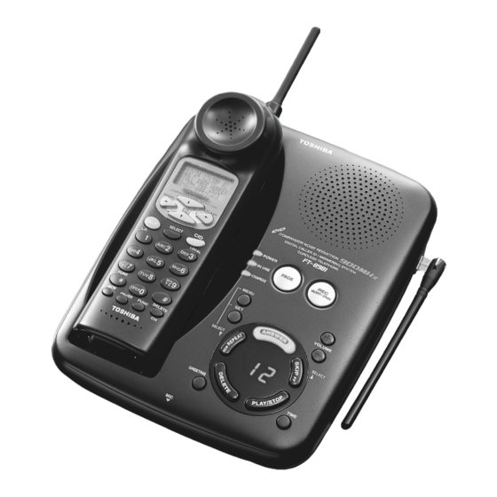
- Page 1 FILE NO. 2B0-200104 SERVICE MANUAL CORDLESS TELEPHONE FT-8981 PUBLISHED IN JAPAN, May, 2001...
-
Page 2: Table Of Contents
CONTENTS SAFETY PRECAUTIONS ........................1 OPERATING CONTROLS ........................2 ANSWERING MACHINE ........................3 ALIGNMENT PROCEDURE ........................4 BLOCK DIAGRAMS ..........................8 SCHEMATIC DIAGRAMS ........................10 TROUBLESHOOTING HINTS ......................14 IC AND TRANSISTOR VOLTAGE CHART ..................21 SEMICONDUCTOR LEAD IDENTIFICATION ..................26 ELECTRICAL PARTS LOCATION ...................... -
Page 3: Operating Controls
OPERATING CONTROLS HANDSET CONTROLS AND FUNCTIONS Dot matrix display Antenna Number of calls LCD Display Date Time VOL/RING Button FLASH Button Caller’s telephone number COMPANDOR NOISE REDUCTION REDIAL FLASH Caller’s name REDIAL Button VOL/ RING SELECT Button TALK Button SELECT CID Button L.D. -
Page 4: Answering Machine
ANSWERING MACHINE SETTING THE CLOCK 1. Press twice, then press MENU 2. Select the day of the week by pressing . When the correct day is announced, SELECT SELECT press 3. Select the hour by pressing . When the correct hour is announced, press SELECT SELECT 4. -
Page 5: Alignment Procedure
ALIGNMENT PROCEDURE Base Unit Transmitter Section Connections BASE Unit AF GEN. Test Point Power Meter DC IN TEL Line 1kHz -15dBm 9V Jack Jack Test Point Frequency Counter AC 120V Adapter 60Hz Deviation Meter Preset Press and hold the “ANSWER” key about 5.0 seconds while turning the 7. SEG LED shows “8” . Alignment Procedure step Adjustment... - Page 6 Receiver Section Connections BASE Unit AC Voltmeter RF SG Dummy Load (600-ohm) TEL Line Test Point Jack DC Voltmeter DC IN 9V Jack Test Point AC 120V 60Hz Adapter Preset Place the Base Unit in RX SENS mode (step 11) in accordance with the precedure on page 4. Alignment Procedure step Preset to...
- Page 7 Handset Unit Transmitter Section Connections HANDSET Unit AF GEN. Test Point Power Meter J603 Battery 1kHz 9mV MIC+Pin Connector Test Point Frequency Counter DC Power Supply Deviation Meter DC 3.8V Preset a) Connect the handset RF unit to the handset main unit. b) Connect DC power supply to battery connector on the handset unit.
- Page 8 Receiver Section Connections HANDSET Unit AC Voltmeter RF SG Dummy Load (150-ohm) Connector Test Point DC Power Supply J603 DC Voltmeter Battery Terminal Connector DC 3.8V Preset a) Connect the handset RF unit to the handset main unit. b) Connect DC power supply to battery connector on the handset unit. c) Turn the DC power supply on while pressing “...
-
Page 9: Block Diagrams
BLOCK DIAGRAMS Base Unit — 8 —... - Page 10 Handset — 9 —...
-
Page 11: Schematic Diagrams
SCHEMATIC DIAGRAMS Base Unit — 10 — — 11 —... - Page 12 Handset — 12 — — 13 —...
-
Page 13: Troubleshooting Hints
TROUBLESHOOTING HINTS 1. The bell does not ring. Set RINGER volume setting Check RINGER mode setting to Hi or Low. is Hi or Low. See 2. The bell does not ring When the PAGE SW of the & page does not ring. base is pressed, does the ringer on the handset ring? When the TEL SG is joined... - Page 14 2. The bell does not ring & page does not ring. Can the base and handset be See 3. The base and handset connected? cannot be connected. Press handset DIAL key When the key of the handset is Check IC603. while in TALK MODE.
- Page 15 3. The base and handset cannot be connected. Check whether the base Check IC4 and its is able to set in the test peripheral circuit. mode 8. Check the TX POWER Check base RF unit. and the TX FREQUENCY on the base unit. Set the base in the test Check whether there is a Check RT3, R76, R91,...
- Page 16 Set the handset in the Check whether there is a Check R635, R636, R634, test mode 3, check 250 Hz data waveform at R632, R619, C610, C611, whether deviation of the "MOD" of RF unit. C669 and RT603. TX data is app. 9.0 kHz Dev.
- Page 17 4. Cannot make a phone call (pulse). Can the base and handset See 3. The base and handset be connected? cannot be connected. While in TALK MODE, press Check IC4. dial key of the handset. Check whether square waveform from pin 80 of IC4 is fed.
- Page 18 6. Voice cannot be transmitted to other party (outgoing call). Can the base and handset be See 3. The base and handset connected? cannot be connected. The 1 kHz, 9.0mV sine Check Q604 and its wavefor m i s a p p l i e d t o peripheral circuit.
- Page 19 7. The voice of the caller cannot be heard (incoming call). Can the base and handset be See 3. The base and handset connected? cannot be connected. The 1 kHz, -15dBm sine Check the base TEL-line waveform is applied to TEL- circuit and REPLAY control line of the base, can the 1 kHz circuit.
-
Page 20: Ic And Transistor Voltage Chart
IC AND TRANSISTOR VOLTAGE CHART TRANSISTORS Unit [V] Unit [V] Ref. Ref. STBY Note TALK Note STBY Note TALK Note 2.1-2.5 0.4-0.6 3.1-3.5 2.32 2.6/3.3 1.0-1.3 -3.1/0.6 -3.6/0.8 0-3.6 Q600 INTERVAL Q601 INTERVAL INTERVAL Q602 Q603 Q604 INTERVAL Q609 INTERVAL Q610 Q611 Q612... - Page 21 Unit [V] IC's Unit [V] Ref. Ref. STBY Note TALK Note STBY Note TALK Note INTERVAL Q613 INTERVAL Q614 Q616 3.5-0.0 DATA(PULSE) 3.5-0.0 DATA(PULSE) Q617 3.9-2.5 X'TAL 3.9-2.5 X'TAL 3.1-2.3 X'TAL 3.1-2.3 X'TAL 2.4-2.0 3.4-3.2 3.4-3.2 2.1-0.8 2.1-1.7 COL00 COL00 COL01 COL01 COL02...
- Page 22 IC's Unit [V] Unit [V] Ref. Ref. STBY Note TALK Note STBY Note TALK Note ROW01 ROW01 ROW02 ROW02 TONE_OUT TONE_OUT Dvcc Dvcc DGND DGND 3.5-0.0 DATA_IN 3.5-0.0 DATA_IN RX_MUTE RX_MUTE TX_MUTE TX_MUTE 3.2-0.0 PLLENB PLLENB 3.2-0.0 PLLDAT PLLDAT 3.2-0.0 PLLCLK PLLCLK TX_CONT...
- Page 23 Unit [V] Unit [V] Ref. Ref. STBY Note TALK Note STBY Note TALK Note INTERVAL INTERVAL INTERVAL INTERVAL INTERVAL INTERVAL INTERVAL INTERVAL SQURE(int) SQURE IC601 INTERVAL INTERVAL INTERVAL None None Connect Connect INTERVAL INTERVAL INTERVAL INTERVAL INTERVAL INTERVAL INTERVAL INTERVAL IC602 INTERVAL INTERVAL...
- Page 24 Unit [V] Unit [V] Ref. Ref. STBY Note TALK Note STBY Note TALK Note None None Connect Connect INTERVAL INTERVAL IC603 with 0.7V sin with 0.7V sin IC603 with1.5VAC(int) with 1.4V sin IC605 None None Connect Connect INTERVAL Vol:Lo INTERVAL INTERVAL SQURE INTERVAL...
-
Page 25: Semiconductor Lead Identification
SEMICONDUCTOR LEAD IDENTIFICATION DIODES 1N4148 RLS4148 SML-310LT HZ33-2 HZK6C SML-310MT HZ33CP HZ4B1 Cathode Anode Anode HZ6B2 Anode Cathode HZ6C3 HZ11A Cathode RB420D 1SS226 EMPG4868K ELD406 Cathode Anode/Cathode 16 15 14 13 12 11 10 9 DIGIT 1 DIGIT 2 Anode (Open) Anode Cathode... - Page 26 D16559 K9F4008WOA CD11 CD12 N.C. N.C. CD13 CD14 N.C. N.C. CD15 N.C. N.C. CA10 N.C. N.C. CA11 N.C. N.C. GPIO15 CA12 N.C. N.C. GPIO14 CA13 GPIO13 CA14 N.C. N.C. GPIO12 CA15 N.C. N.C. GPIO11 N.C. N.C. GPIO10 N.C. N.C. GPIO9 RASN N.C.
-
Page 27: Electrical Parts Location
ELECTRICAL PARTS LOCATION Base Unit Main PCB — 28 —... - Page 28 Handset Main PCB — 29 —...
-
Page 29: Wiring Diagrams
WIRING DIAGRAMS Base Unit — 30 —... - Page 30 Handset — 31 —...
-
Page 31: Exploded View And Mechanical Parts List
EXPLODED VIEW AND MECHANICAL PARTS LIST RF MODULE (HANDSET) BASE MAIN PCB ASSY SP751 RF MODULE (BASE) HANDSET SP801 MAIN PCB ASSY BASE KEY PCB ASSY AT751 — 32 —... - Page 32 LOC. PART NO. REF NO. DESCRIPTION RC009896 GNBZ366565Z BUTTON, FUNCTION RC009557 GNBZ447715Z BUTTON, FUNCTION RC009897 GNBZ467967Z BUTTON, FUNCTION RC009898 GNBZ467968Z BUTTON, PUSH PMMA RC009894 GCAS266581Z CASE, BOTTOM RC009914 GCAS266566Z CASE, TOP RC009325 HTML446079Z CHARGE TERMINAL C5191(PBP) RC009396 GCAS346381Z DISPLAY WINDOW PMMA RC009837 LFUT494200Z...
-
Page 33: Parts List
PARTS LIST PRODUCT SAFETY NOTE: Products marked with a have special characteristics important to safety. Before replacing any of these components, read carefully the product safety notice of this service manual. Don’ t degrade the safety of the product through important servicing. Symbol Symbol ±1... - Page 34 LOC. PART NO. REF NO. DESCRIPTION C042 RC005468 BCEQ904706Z C:ELECTROLYTIC 47UF 6.3V M C-125 C043 RC005202 BCML311045Z C:CERAMIC M/L (1608) TAPE 0.1UF 16V K B C044 RC005202 BCML311045Z C:CERAMIC M/L (1608) TAPE 0.1UF 16V K B C045 RC008269 BCML316835Z C:CERAMIC M/L (1608) TAPE 0.068UF 16V K B C046 RC005202...
- Page 35 LOC. PART NO. REF NO. DESCRIPTION C106 RC001798 BCAZ114716Z C:ELECTROLYTIC 470UF 10V M C-156 C107 RC005205 BCML811035Z C:CERAMIC M/L (1608) TAPE 0.01UF 50V K B C108 RC001794 BCAZ111016Z C:ELECTROLYTIC 100UF 10V M C-156 C109 RC005205 BCML811035Z C:CERAMIC M/L (1608) TAPE 0.01UF 50V K B C110 RC004445...
- Page 36 LOC. PART NO. REF NO. DESCRIPTION C165 RC008731 BCXK311050Z C:CERAMIC M/L (2125) TAPE 1UF 16V Z F C166 RC005420 BCMM811514Z C:CERAMIC M/L (1608) TAPE 150PF 50V J CH C167 RC005202 BCML311045Z C:CERAMIC M/L (1608) TAPE 0.1UF 16V K B C168 RC005202 BCML311045Z C:CERAMIC M/L (1608) TAPE...
- Page 37 LOC. PART NO. REF NO. DESCRIPTION C650 RC005202 BCML311045Z C:CERAMIC M/L (1608) TAPE 0.1UF 16V K B C651 RC005420 BCMM811514Z C:CERAMIC M/L (1608) TAPE 150PF 50V J CH C652 RC005420 BCMM811514Z C:CERAMIC M/L (1608) TAPE 150PF 50V J CH C653 RC005204 BCML811025Z C:CERAMIC M/L (1608) TAPE...
- Page 38 LOC. PART NO. REF NO. DESCRIPTION D017 RC002236 BDAY0246003 DIODE:AX TS 26+ 1N4148 T-77 D019 RC002236 BDAY0246003 DIODE:AX TS 26+ 1N4148 T-77 D020 RC002471 BDAY0492045 DIODE:ZENER AX TS 26+ HZ6C3 TD D021 RC002236 BDAY0246003 DIODE:AX TS 26+ 1N4148 T-77 D026 RC002236 BDAY0246003 DIODE:AX TS 26+...
- Page 39 LOC. PART NO. REF NO. DESCRIPTION COILS L001 RC004073 BLZY0051479 INDUCTOR:MOLDED LZ-051 SP0305-4R7K 4.7UH L002 RC008397 BLZY0136100 INDUCTOR:MOLDED CHIP LZ-136 MLF1608K100KT 10UH L003 RC004073 BLZY0051479 INDUCTOR:MOLDED LZ-051 SP0305-4R7K 4.7UH L004 RC008281 BLBY1175001 COIL LB-1175 7002BE-A0026HM L005 RC004073 BLZY0051479 INDUCTOR:MOLDED LZ-051 SP0305-4R7K 4.7UH L006 RC008451 BLZY0181826...
- Page 40 LOC. PART NO. REF NO. DESCRIPTION Q614 RC003031 BDBC1623648 TRANSISTOR DB-380 2SC1623-L6 T1B Q616 RC003031 BDBC1623648 TRANSISTOR DB-380 2SC1623-L6 T1B Q617 RC003031 BDBC1623648 TRANSISTOR DB-380 2SC1623-L6 T1B RESISTORS R001 RC005249 BRFC162244Z R:CARBON FIXED CHIP 220K 1/16W J TAPE R002 RC005252 BRFC163314Z R:CARBON FIXED CHIP 330 1/16W J TAPE...
- Page 41 LOC. PART NO. REF NO. DESCRIPTION R054 RC005279 BRFC161514Z R:CARBON FIXED CHIP 150 1/16W J TAPE R055 RC009303 BRFC164794Z R:CARBON FIXED CHIP 4.7 1/16W J TAPE R056 RC009303 BRFC164794Z R:CARBON FIXED CHIP 4.7 1/16W J TAPE R057 RC008558 BRPA613944Z R:CARBON AXIAL LEAD (26) 390K 1/6W J TAPING R058 RC008558...
- Page 42 LOC. PART NO. REF NO. DESCRIPTION R111 RC005281 BRFC162224Z R:CARBON FIXED CHIP 2.2K 1/16W J TAPE R112 RC008091 BRFC165614Z R:CARBON FIXED CHIP 560 1/16W J TAPE R113 RC005241 BRFC161034Z R:CARBON FIXED CHIP 10K 1/16W J TAPE R114 RC005240 BRFC161024Z R:CARBON FIXED CHIP 1K 1/16W J TAPE R115 RC005248...
- Page 43 LOC. PART NO. REF NO. DESCRIPTION R174 RC005240 BRFC161024Z R:CARBON FIXED CHIP 1K 1/16W J TAPE R175 RC005240 BRFC161024Z R:CARBON FIXED CHIP 1K 1/16W J TAPE R176 RC005240 BRFC161024Z R:CARBON FIXED CHIP 1K 1/16W J TAPE R177 RC005242 BRFC161044Z R:CARBON FIXED CHIP 100K 1/16W J TAPE R178 RC005240...
- Page 44 LOC. PART NO. REF NO. DESCRIPTION R268 RC005280 BRFC161534Z R:CARBON FIXED CHIP 15K 1/16W J TAPE R269 RC005241 BRFC161034Z R:CARBON FIXED CHIP 10K 1/16W J TAPE R600 RC005248 BRFC162234Z R:CARBON FIXED CHIP 22K 1/16W J TAPE R601 RC005256 BRFC164724Z R:CARBON FIXED CHIP 4.7K 1/16W J TAPE R602 RC005256...
- Page 45 LOC. PART NO. REF NO. DESCRIPTION R655 RC005241 BRFC161034Z R:CARBON FIXED CHIP 10K 1/16W J TAPE R656 RC005240 BRFC161024Z R:CARBON FIXED CHIP 1K 1/16W J TAPE R658 RC005286 BRFC165644Z R:CARBON FIXED CHIP 560K 1/16W J TAPE R659 RC005242 BRFC161044Z R:CARBON FIXED CHIP 100K 1/16W J TAPE R660 RC005247...
- Page 46 LOC. PART NO. REF NO. DESCRIPTION RT002 RC009721 BRTY0578104 R:SEMI-FIXED RT-578 VZ067TL7B104 100KB RT003 RC009722 BRTY0578203 R:SEMI-FIXED RT-578 VZ067TL7B203 20KB RT601 RC008328 BRTY0569224 R:SEMI-FIXED RT-569 POZ3AN-1-224N-T00 RT602 RC008326 BRTY0569104 R:SEMI-FIXED RT-569 POZ3AN-1-104N-T00 RT603 RC008327 BRTY0569223 R:SEMI-FIXED RT-569 POZ3AN-1-223N-T00 CRYSTALS X001 RC009888 BQXY0760001 CRYSTAL...
-
Page 47: Assembly Parts List
ASSEMBLY PARTS LIST NOTE: Following part numbers are not available as replacement parts. Order parts necessary for repair or contact the Toshiba Factory Service Center. LOC. PART NO. REF NO. DESCRIPTION RC009909 AC316BHBA BASE MAIN PCB ASSEMBLY RC009877 AC315BHBC BASE KEY PCB ASSEMBLY... -
Page 48: Specifications
SPECIFICATIONS MEASUREMENT CONDITIONS 1. Standard Voltage: DC 3.8 V ±0.025 V Portable Unit AC 120 V ±3 V 60 Hz Base Unit 25 °C ±5 °C 2. Temperature: 3. Channel: Portable (TX Frequency) Base (TX Frequency) 904.052470 MHz 925.997470 MHz 902.102465 MHz 926.047470 MHz 902.152465 MHz... -
Page 49: Base Unit
BASE UNIT RECEIVER Unit Nominal Limit −115 < −107 1. Sensitivity 12 dB SINAD (with CCITT Filter) 2. Frequency Response (Ref: 1 kHz) −5.0 −9.0 ~ −1.0 0.3 kHz −8.0 −12.0 ~ −4.0 3.0 kHz 3. Distortion at 1 mV RF Input <... - Page 50 HANDSET UNIT RECEIVER Unit Nominal Limit −115 1. Sensitivity 12 dB SINAD (with CCITT Filter) <−107 2. AF Frequency Response (Ref: 1 kHz) 0.3 kHz 3.0 ~ 11.0 −14.5 −18.5 ~ −10.5 3.0 kHz −8.0 −11 ~ −5 3. Audio Output Level VOL.
- Page 51 FSK SENSITIVITY (ON HOOK) −44.0 1. Minimum Acceptable Signal Level: <−36.0 (with 25dB S/N ratio) −12< 2. Maximum Acceptable Signal Level: (with 25dB S/N ratio) OTHERS Ni-Cd Battery 600 mAH (@1.2 V × 3 = 3.6 V) 1. Battery: 2. Memory: 10 Memories (NAME : 14 Digits, Number : 20 Digits) + 1 Redial Memory (32 Digits) + 20CID Memories (NAME : 15 Digits, Number : 15 Digits)
- Page 52 TOSHIBA AMERICA CONSUMER PRODUCTS, INC. 82 TOTOWA ROAD, WAYNE, N.J. 07470 TOSHIBA HAWAII, INC. 327 KAMAKEE ST., HONOLULU, H.I. 96814...
Need help?
Do you have a question about the FT-8981 and is the answer not in the manual?
Questions and answers