Table of Contents
Advertisement
Quick Links
SERVICE MANUAL
Ver 1.0 2002. 01
Sony Corporation
9-873-492-01
2002A0400-1
Personal Audio Company
© 2002. 1
Published by Sony Engineering Corporation
SPECIFICATIONS
Input
4 Channels
S Video, Video, Audio (L/R) × 3
Video, Audio (L/R) × 1
S Video, Video, Audio (L/R) × 1
Output
Dimensions
Approx. 7
1/4
(184 × 54 × 142 mm) (w/h/d)
Mass
Approx. 13 oz. (360 g)
Power
AC power adaptor
120 V AC
6 V DC
Optional accessories AC power adaptor (1)
Design and specifications are subject to change without
notice.
The "CE" printed on the unit is available only for the EU
member nations.
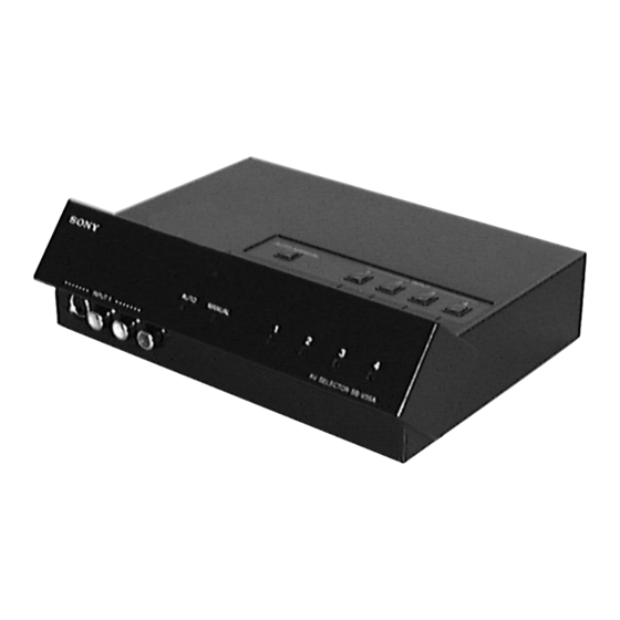
SB-V55A
× 2
× 5
inches
1/4
5/8
US Model
AV SELECTOR
1
Advertisement
Table of Contents

Related Manuals for Sony SB-V55A


Summary of Contents for Sony SB-V55A
- Page 1 Design and specifications are subject to change without notice. The “CE” printed on the unit is available only for the EU member nations. AV SELECTOR Sony Corporation 9-873-492-01 2002A0400-1 Personal Audio Company © 2002. 1 Published by Sony Engineering Corporation...
-
Page 2: Table Of Contents
COMPONENTS IDENTIFIED BY MARK 0 OR DOTTED LINE WITH MARK 0 ON THE SCHEMATIC DIAGRAMS AND IN THE PARTS LIST ARE CRITICAL TO SAFE OPERATION. REPLACE THESE COMPONENTS WITH SONY PARTS WHOSE PART NUMBERS APPEAR AS SHOWN IN THIS MANUAL OR IN SUPPLEMENTS PUBLISHED BY SONY. -
Page 3: General
SB-V55A SECTION 1 GENERAL This section is extracted from instruction manual. -
Page 4: Disassembly
SB-V55A SECTION 2 DISASSEMBLY Note : Follow the disassembly procedure in the numerical order given. 2-1. COVER, UPPER 1 P 3x8 6 cover,upper 2 P 3x8 4 BTP 2.6x10 3 BTP 2.6x10 2-2. MAIN BOARD 1 BTP 2.6x5 3 MAIN board... -
Page 5: Diagrams
SB-V55A SECTION 3 DIAGRAMS 3-1. IC PIN DESCRIPTION • IC5 M34513 (SYSTEM CONTROL) Pin No. Pin Name Pin Description Output port (LED (D5) light signal output in this set.) Output port (LED (D6) light signal output in this set.) Output port (LED (D7) light signal output in this set.) -
Page 6: Block Diagram -Main Section
SB-V55A 3-2. BLOCK DIAGRAM — MAIN SECTION — CC-15 BOARD 4FSC CLOCK +4.9V L MODE LCH SWITCH GENERATOR (B+) J2(4/4) J2(1/4) L1 IN AUDIO L1 OUT INPUT 4 VCC1 L2 IN VCC2 J6(1/4) L3 IN CLMIN AUDIO AUDIO 4FSCOUT INPUT 1... - Page 7 SB-V55A • Waveforms THIS NOTE IS COMMON FOR PRINTED WIRING BOARDS AND SCHEMATIC DIAGRAMS. (In addition to this, the necessary note is printed in each block.) 0.35Vp-p for schematic diagram: • All capacitors are in µF unless otherwise noted. pF: µµF 503.5kHz...
-
Page 8: Printed Wiring Board -Main Section
SB-V55A 3-3. PRINTED WIRING BOARD — MAIN SECTION — • Refer to page 7 for Note. CC-15 BOARD (SIDE A) • Semiconductor Location Ref. No. Location H-11 H-10 E-10 F-11 1-680-503-... - Page 9 SB-V55A OUTPUT INPUT 4 OUTPUT INPUT 4 OUTPUT INPUT 4 OUTPUT INPUT 3 INPUT 2 INPUT 3 INPUT 2 INPUT 3 INPUT 2 INPUT 2 INPUT 3 DC IN 6V AUDIO AUDIO AUDIO AUDIO AUDIO AUDIO AUDIO AUDIO VIDEO VIDEO...
-
Page 10: Schematic Diagram -Main Section
SB-V55A • Refer to page 7 for Note and Waveforms. 3-4. SCHEMATIC DIAGRAM — MAIN SECTION — • Refer to page 11 for IC Block Diagrams. J2(2/2) IC B/D J4(1/2) J4(2/2) IC B/D IC B/D J2(1/2) - Page 11 SB-V55A • IC BLOCK DIAGRAMS IC3 MM1069XS SYNC. SEPARATION 1/32 SYNC. 32fH PHASE FREQUENCY DISCRIMINATION COMPARATOR DIVISION IC6 TC90A45 AVSS 16 ADDD ADIN 15 YOUT CLAMP DYNAMIC COLLOR 14 BIAS2 COMFILTER KILLER 1H LINE BIAS1 MEMORY TEST 13 COUT 12 BIAS3...
- Page 12 SB-V55A IC7 MM1093NF CLMIN CMPIN SYNC ACCF 4FSCOUT APC1F APC1 APC2 APC2F VCXO DIVIDER GND1 (1/4) GND2 4FSC FSCOUT VCC2 VCC1...
-
Page 13: Exploded Views
SB-V55A SECTION 4 EXPLODED VIEWS NOTE: • The mechanical parts with no reference • Color Indication of Appearance Parts number in the exploded views are not supplied. Example : • Items marked “*” are not stocked since KNOB, BALANCE (WHITE) ... (RED) they are seldom required for routine service. -
Page 14: Electrical Parts List
SB-V55A SECTION 5 CC-15 ELECTRICAL PARTS LIST NOTE: • Due to standardization, replacements in • Items marked “*” are not stocked since The components identified by mark 0 or dotted line with mark the parts list may be different from the they are seldom required for routine service. - Page 15 SB-V55A CC-15 Ref. No. Part No. Description Remark Ref. No. Part No. Description Remark LED SLP-289C-51 (2) 1-216-813-11 METAL CHIP 1/16W LED SLP-289C-51 (3) 1-216-813-11 METAL CHIP 1/16W LED SLP-289C-51 (4) 1-216-821-11 METAL CHIP 1/16W 8-719-988-61 DIODE 1SS355TE-17 1-216-845-11 METAL CHIP...
- Page 16 SB-V55A CC-15 Ref. No. Part No. Description Remark < SWITCH > SWITCH (INPUT1) SWITCH (INPUT2) SWITCH (INPUT3) SWITCH (INPUT4) SWITCH (AUTO/MANUAL) < VIBRATOR > 1-579-583-11 VIBRATOR, CERAMIC (503.5kHz) 1-781-282-11 VIBRATOR, CERAMIC (4MHz) VIBRATOR, CERAMIC (3.58MHz) ************************************************************* ACCESSORIES ************ 1-476-269-11 ADAPTOR, AC (AC-E6TR1)
- Page 17 SB-V55A MEMO...
- Page 18 SB-V55A REVISION HISTORY Clicking the version allows you to jump to the revised page. Also, clicking the version at the upper right on the revised page allows you to jump to the next revised page. Ver. Date Description of Revision...
Need help?
Do you have a question about the SB-V55A and is the answer not in the manual?
Questions and answers