Advertisement
Quick Links
Advertisement

Related Manuals for Super Gym SG8018MT

Summary of Contents for Super Gym SG8018MT
- Page 1 SG8018MT Leg Extension Assembly Instructions...
-
Page 2: Table Of Contents
Table of contents Important Safety Instructions-------------------------------------------------------- 1 Exploded View Diagram---------------------------------------------------------------- 2 Hardware List----------------------------------------------------------------------------- 3 Parts List----------------------------------------------------------------------------------- 5 Assembly instructions----------------------------------------------------------------- 6... -
Page 3: Important Safety Instructions
Important Safety Instructions Before beginning any fitness program, you should obtain a complete physical examination from your physician. When using exercise equipment, basic precautions should always be taken, including the following: * Read all instructions before using the Leg Extension. These instructions are written to ensure your safety and to protect the unit. -
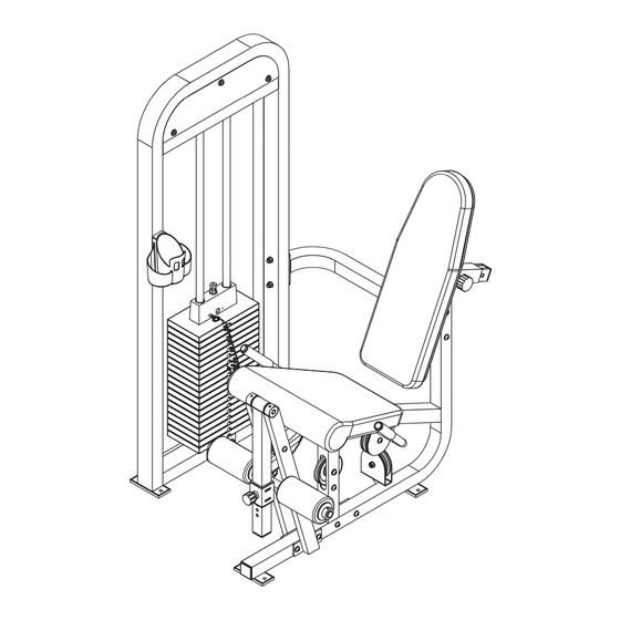
Page 4: Exploded View Diagram
Leg Extension Exploded View Diagram... -
Page 5: Hardware List
Hardware List... - Page 6 Hardware List...
-
Page 7: Parts List
Parts List Description Description Item No. Item No. Main Upright 32 Plastic Washer Low Cross Brace 33 Plug φ25 Upper Cross Brace 34 Bearing Seat Frame 35 Leg Extension Pivot Right Support Tube 36 Collar Left Support Tube 37 Weight Pin Swivel Frame 38 Pulley Spacer Slide Roller Pad Frame... -
Page 8: Assembly Instructions
Assembly Instructions Assembly of the Leg Extension takes professional installers about 2 hours. If this is the first time you have assembled this type of equipment, plan to spend more time. It is strongly recommended to assemble the equipment by professional installers. - Page 9 Step1 Install the Sub-Support Component 1. Attach Low Cross Brace (#2) and Upper Cross Brace (#3) to Main Upright (#1) using: two Allen Bolts (#40) M10*95 two Allen Bolts (#43) M10*75 eight Washers (#52) four Nylon Lock nuts (#53) M10 2.
- Page 10 Step2 Assemble Leg Extension 1. Attach Right Support Tube (#5) and Left Support Tube (#6) to the Seat Frame (#4) using: two Allen Bolts (#41) M10*80 six Washers (#52) three Nylon Locknuts(#53) M10 one Allen Bolt (#39) M10*130 2. Insert Leg Extension Pivot (#35) to Right Support Tube (#5) Swivel Frame (#7) and Left Support Tube (#6) then secure them using: two Allen Screw (#48) M8*12...
- Page 11 Step3 Assemble Weight Stack 1. Insert both the Guide Rods(#11) into the Main Upright (#1). 2. Slide Weight Stack Bumper (#17) down onto each the Guide Rod(#11). 3. Carefully begin sliding the Weight Plate one by one in sequence: #15,#14 4.
- Page 12 Step4 Route The Cable 1. Connect the looped end of Cable (#16) to the Bracket weld on the Swivel Frame (#7) secure it using: one Allen Bolt(#46) M10*40 two Washers (#52) one Nylon Locknut(#53) M10 2. Pass Cable through the window of the Seat Frame (#4) and route under the Pulley (#21) and secure to Seat Frame (#4) using: one Allen Bolt (#43) M10*75 two Washers (#52)
- Page 13 Step5 Route The Cable 1. Route the Cable under the Pulley and attach to pulley bracket weld on the Seat Frame (#4) using: one Allen Bolt (#45) M10*50 two Washers (#52) one Nylon Lock Nut(#53) M10 2. Route the Cable under the Pulley and attach to pulley bracket weld on the Main Upright (#1) using: one Allen bolt (#45) M10*50 two Washers (#52)
- Page 14 Step6 Route The Cable 1. Pass the Cable through the window of the Main Upright (#1) and route the cable over the Pulley (#21) attach the long pulley bracket weld on the Main Upright (#1) using : one Allen bolt (#45) M10*50 two Washers (#52) one Nylon Lock Nut (#53) M10 The same way to attach another pulley .
- Page 15 Step7 Assemble The Handle 1. Attach Handle (#10) to the Seat Frame (#4) using : two Allen Bolts (#41) M10*80 four Washers (#52) two Nylon Lock Nuts (#53) M10 2. Attach Seat Pad (#20) to the Seat Frame (#4) using: two Allen Bolts (#41) M10*80 four Washers (#52)
- Page 16 Step8 Assemble Back Pads 1. Attach Back Pads (#19) to Back Pad Support (#9) using: two Allen Bolts (#45) M10*50 two Washers (#52) 2. Insert the Back Pad Support (#9) into the Seat Frame (#1) and locate by Big Pop Pin.
- Page 17 Step9 Assemble Pads and Holder Bottle 1. Align four Plastic Washers (#32) two Roller Pads (#23) to Slide Roller Frame (#8) and then secure them using: two Collars(#36) two Allen Screws (49) 2. Put Slide Roller Frame (#8) onto the Swivel Frame (#7), locate it by small Pop Pin (#27).
- Page 18 Step10 Assemble Shroud 1. Attach two Upper Shrouds (#12) to Main Upright (#1) using: six Allen Bolts (#50) M8*15 six Washers (#54) φ8 2. Attach Weight Shroud (#13) to Main Upright (#1) using: four Allen Bolts (#50) M8*15 four Washers (#54) φ8...
Need help?
Do you have a question about the SG8018MT and is the answer not in the manual?
Questions and answers