
Related Manuals for Wahlberg Winch 10


Summary of Contents for Wahlberg Winch 10
- Page 1 Winch 10 Item No .241 User Manual WWW.WAHLBERG.DK · TELEPHONE +45 86 18 14 20 · EMAIL: sales@wahlberg.dk...
-
Page 2: Safety Information
Read this manual before installing, powering or servicing the winch; follow the safety precautions listed below and observe all warnings in this manual and printed on the winch. If you have questions about how to operate the winch safely, please contact you Wahlberg Motion Design supplier or Wahlberg Motion Design. -
Page 3: Index
Do not modify the winch in any way not described in this manual. Install only genuine Wahlberg parts. PROTECTION FROM INJURY Fasten the winch securely to a fixed surface, rig, or structure when in use. The winch is not portable when installed. - Page 4 Disposing of this product Wahlberg Motion Design products are supplied in compliance with Directive 2002/96/EC of the European Parliament and of the Council of the European Union on WEEE (Waste Electrical and Electronic Equipment), as amended by Directive 2003/108/EC, where applicable.
-
Page 5: Table Of Contents
............................21 SITE SERVICE ............................21 IFE OF THE WIRE ............................. 21 PARE PARTS ............................22 IRE DEFECT ............................23 HANGING WIRE ............................26 PPLYING WIRE ............................26 OWER DEFECT WINCH 10 - CHEAT SHEET 805.241.011 Date: March 22 , 2017... -
Page 6: Technical Specifications
Technical specifications Model: Winch 10 Item no.: .241 Dimensions: 240 × 210 × 150 mm. / 9.5 × 8.3 × 5.19 in. (L×W×H) (Without mounting clamp) Power supply: 230 V AC 50 Hz (optional 120V/60Hz). Power consumption: Max 200 Watt. -
Page 7: Introduction
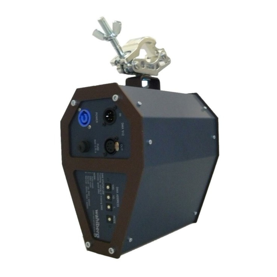
Description Winch 10 is a mini winch for stage use, mainly for use in theatres, shows and concerts. It lifts props and small set pieces in and out of the stage sphere at maximum load of 10 kg up and down. -
Page 8: Area Of Use
Caution! To reduce the risk of electric shock, do not expose to rain: store indoors! Using for the first time Important! The winch 10 must be protected from environmental factors such as physical shocks and vibration during transportation and storage. -
Page 9: Physical Installation
Physical installation Warning! The Winch 10 must be either fastened to a flat surface such as a roof, or clamped to a truss or similar structure in such a way that the wire exit points downwards. Do not apply power to the Winch 10 if it is not securely fastened. -
Page 10: Ac Power
AC power Warning! Read “Safety Information” on page 2 before connecting the winch 10 to AC mains power. Warning! For protection from electric shock, the Winch 10 must be grounded (earthed). The power distribution circuit must be equipped with a fuse or circuit breaker and ground-fault (earth-fault) protection. -
Page 11: Installing A Power Input Connector On A Power Cable
Installing a power input connector on a power cable To install a Neutrik powerCON TRUE1 NAC3FX-W input connector on a power Cable, follow the original Neutrik instructions below: 805.241.011 Date: March 22 , 2017... - Page 12 805.241.011 Date: March 22 , 2017...
-
Page 13: Data Link
XLR connectors for DMX data input and output. The pin-out on all connectors is pin 1 = shield, pin 2 = (-), and pin 3 = (+). Pins 4 and 5 in the 5-pin XLR connectors are not used in the Winch 10 but are available for possible additional data signals as required by the DMX512-A standard. -
Page 14: Setup
Warning! Before running the winch, it is important to put a counterbalance on the wire. This is necessary, as the slack detection switch otherwise will be activated and stop the winch. Warning! Only experienced DMX users should operate the winch. Contact Wahlberg for further information and education on DMX protocol. - Page 15 MODE 2 - Positioning with MANUAL reset The winch is manually reset on the DMX channels 6 or 7. The top-position is, because of this, also set manually, which makes it possible to decide the position of the top-position. We suggest anyway that it is set near by the motor-house. When the winch has been reset, it is possible to use it in positioning mode.
-
Page 16: Dmx Address Setting
The DMX address is configured using the three DMX ADDRESS selectors on the winch. The selected DMX address states from which channels, on the lighting desk, the winch is controlled. The DMX address can be selected from 1 – 505. The Winch 10 uses 7× DMX channels. DMX channel 1 – Position rough: This channel controls the position of the winch, with the speed (DMX channel 3). -
Page 17: Manual Reset
DMX channel 6 – Find TOP position, moving UP: The channel is used to manually finding the top-position. The channel controls the speed from 0- 100%. The winch starts to run up when channel 6 is set above 0 %. When the winch reaches the wanted top-position, the speed must be set to 0 %, so that the motor stops. -
Page 18: Positioning
Positioning When the winch has been reset and the top-position is set, it is possible to use it for positioning run. The green LED next to the MODE selector indicates, by fast flashing, that the winch needs to be reset, before it can be used. -
Page 19: Controlling The Top- And Bottom Positions
Controlling the top- and bottom positions The top-position needs to be reset automatically or manually, before the winch is able to use for positioning run. To get the most precise run, fit for your own needs, it is possible to regulate the top- and bottom-positions. -
Page 20: Service And Maintenance
Service and maintenance Warning! Read “Safety Information” on page 2 before servicing the Winch 10. Warning! Disconnect the Winch from AC mains power and allow cooling down for at least 10 minutes before handling. Warning! Refer any service operation not described in this user manual to a qualified service technician. -
Page 21: On-Site Service
The wire should be inspected long before these numbers are reached and checked for damages, and replaced if necessary Spare parts Only parts ordered at or approved by Wahlberg should be used in the winch to ensure product function and stability. Contact Wahlberg to inquire about spare parts. 805.241.011... -
Page 22: Wire Defect
Wire defect If the wire in any way gets damaged, get stuck or have problems rolling on and off, the wire and wire roll-up needs to be inspected. This can be done the following way: 1. Disconnect the power. 2. Remove the six 3mm hexagonal socket screws, on one of the middle plates on the winch. -
Page 23: Changing Wire
If the wire has any damaged the winch must not be used before the wire has been replaced (See section “Spare parts” on page 21). This can be done following the instructions below, or by Wahlberg. Please contact Wahlberg for information regarding approved spare parts and questions for the procedure. - Page 24 13. Form an eye with the new wire and a ferrule (approved by Wahlberg), using the old eye as template. 14. Place the eye over the axel of the wire-wheel. 15. Mount the wire-wheel back on the winch. You might need to take out the slack detection to make it fit in.
- Page 25 Attention! The wire stop is essential for the function of the winch. Forgetting it will damage the winch! 23. Roll up the last bit of the wire. 24. Mount the middle plate on the winch again and fasten it with the six 3mm hexagonal socket screws per plate.
-
Page 26: Applying Wire
Applying wire Warning! Be careful not to touch the power supply inside the winch, as it is exposed. This can cause an electric shock and damage the winch. Warning! Be careful not to get fingers or likewise caught in the wire-wheel as it turns. This can damage you and the winch. -
Page 27: Winch 10 - Cheat Sheet
Winch 10 - Cheat Sheet MODE Functions Function channels Neutral function – motor stops Position rough (Hi of a 16 bit DMX channel) Positioning with auto TOP reset Position fine (Lo of a 16 bit DMX channel) Positioning with manual TOP reset...
Need help?
Do you have a question about the Winch 10 and is the answer not in the manual?
Questions and answers