Table of Contents
Advertisement
Quick Links
Installation Manual v3.0:
2004-2005 Dodge
Cummins
Please read all instructions before the installation of the ATS Co-Pilot
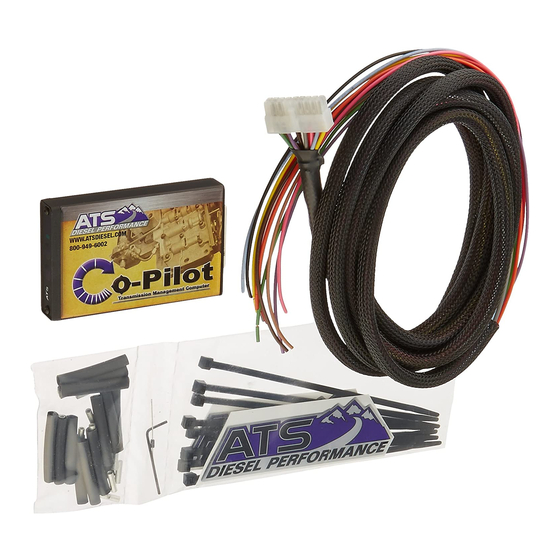
Thank you for purchasing the ATS Co-Pilot Torque converter/exhaust brake controller. This
manual is to assist you with your installation and operation of the unit. If you are installing the
unit for a customer, please pass this manual on to your customer for future reference.
Understanding the ATS Five Star Co-Pilot
The ATS Co-Pilot transmission controller is recommended for use with light duty pickup trucks
when a heavy-duty aftermarket transmission and torque converter package have been installed on
vehicle. While the Co-Pilot will still function perfectly on a stock transmission, factory
transmission shafts are weak and prone to breakage. The factory torque converter clutch will also
fail if applied under high load conditions. Factory computers are programmed to disengage
lockup under certain conditions which will protect the transmissions internal components under
higher load. This is why we recommend having a heavy-duty aftermarket transmission installed
in your vehicle to prevent transmission failure. ATS Diesel Performance sells many parts for all
levels of trucks that will strengthen your transmission and improve reliability, whether you have
a stock daily driver or a fully built race truck! Give us a call today if you feel the need to get a
fully rebuilt transmission for your truck, or if you just want to strengthen your current
transmission with a few upgraded parts. Our experts can help answer any questions you have and
guide you in the right direction.
Advertisement
Table of Contents

Related Manuals for ATS Co-Pilot


Summary of Contents for ATS Co-Pilot
- Page 1 Understanding the ATS Five Star Co-Pilot The ATS Co-Pilot transmission controller is recommended for use with light duty pickup trucks when a heavy-duty aftermarket transmission and torque converter package have been installed on vehicle.
- Page 2 Co-Pilot Adjustment The control panel on the face of the ATS Co-Pilot allows the driver to adjust the lockup of the transmission. Keep in mind that the Co-Pilot will only lock the torque converter when enough boost is reached. This keeps the engine from bogging down due to excessively early converter clutch lockup that is commanded by many factory transmission control modules.
- Page 3 (4) switches on the circuit board; the switches allow the user to select the features desired. The settings are listed below. When reinstalling the face on the Co-Pilot do not over tighten the 2 small screws on the face or faceplate damage will result.
- Page 4 --------------------------------------------------------------------------------------------------------------------------------------- Switch #1 If your Dodge’s transmission has a stock valve body flip #1 switch to ON position If your Dodge’s transmission has an ATS valve body flip #1 switch to OFF position --------------------------------------------------------------------------------------------------------------------------------------- Switch #2 Automatically cancels OD from a stop, only cancels after ignition has cycled, cancels at speed above 3mph.
- Page 5 Co-Pilot Mounting Location Find a convenient location to mount the Co-Pilot within reach and view of the driver. We recommend locating the unit just to the right of the driver on the lower dash panel (above the driver’s right knee). Use the supplied Velcro to secure it to the dash. Before sticking the Velcro to the dash thoroughly clean the area with a cleaner such as acetone or brake clean.
- Page 7 Wiring the Co-Pilot The Co-Pilot has several connections that need to be made in order for it to function properly. There are several wires which are optional but still included to give the Co-Pilot a more versatile use depending on your trucks current setup. Use the diagram below as a reference when installing your Co-Pilot to avoid any conflicts or confusion.
- Page 8 Protect this connection. -Red Wire- +12V Power - Co-Pilot Harness PIN #1 Reasons for use: The red wire supply’s key on power to the Co-Pilot so it can turn on and be functional. NOT OPTIONAL Where to connect it: On the C2 connector of the PCM which is located on the driver’s side of the engine block.
- Page 9 Co-Pilot wire to the 12 V power wire. Protect this connection. -Black Wire- GND Ground - PIN #9 Reason for use: The black wire supply’s ground to the Co-Pilot so the Co-Pilot can turn on and function. NOT OPTIONAL Where to connect it: On the C2 connector of the PCM which is located on the driver’s side of...
- Page 10 Co-Pilot’s white wire to the PCM dark green wire. Protect this connection. -Green Wire- Vehicle Speed Sensor (VSS) - PIN #17 Reasons for use: This is how the Co-Pilot is able to know what speed of the vehicle is traveling so it can control the TCC lock up speed. NOT OPTIONAL Where to connect it: On the C2 connector of the PCM which is located on the driver’s side of...
- Page 11 How to connect it: Strip back approximately ½” of the insulation from the dark green with yellow tracer wire and solder the Co-Pilot’s tan wire to the dark green with yellow. Protect this connection.
- Page 12 There is a stripe on the diode that indicates the positive side. Attach the positive side of the diode to pin 85 of the Pacbrake relay. Attach the negative side of the diode to the gray Co-Pilot wire. See the provided wiring diagram for clarification.
- Page 13 If you experience problems after installation, simply unplug the wiring harness from the back of the Co-Pilot module and put a bent paperclip into blue and yellow terminals of the harness’ plug (jumper the blue and yellow together). This reconnects the wire that you cut at the...
Need help?
Do you have a question about the Co-Pilot and is the answer not in the manual?
Questions and answers