N2MB Racing WOT Box Installation Instructions Manual
1996-2004 ford mustang, svt, cobra
Hide thumbs
Also See for WOT Box:
- Installation instructions manual (13 pages) ,
- Installation instructions manual (13 pages)
Advertisement
Quick Links
1996 ‐2004 Ford Mustang, SVT, Cobra
N2MB WOT Box Installation Instructions
NOTE: If you have a CDI (capacitive discharge ignition system) please contact us at
support@n2mb.com for additional instructions. Damage to your WOT Box can occur if the
installation is not completed correctly!
WARNING: Spark‐based rev‐limiters can damage catalytic converters. If you have catalytic
converters on your car, N2MB accepts no responsibility for damage caused by the WOT Box.
This being said, many successful installs have been made on Catalytic‐Converter equipped
vehicles. Damage usually is only caused by using the launch‐control feature for more than a
few seconds, but once again, USE AT YOUR OWN RISK IF YOU HAVE CATALYTIC CONVERTERS!
Please visit our website at http://www.n2mb.com for the latest version of the WOT Box
software and installation instructions.
Solder all joints. The N2MB recommended soldering method is available at
http://www.n2mb.com. Use a multimeter to verify all wires before they are cut or tapped
into. The colors of wires from model year to model year may differ, and may be different on
your car from those described in these instructions. Where discrepancies are known, they
are described, but there may be more discrepancies than those listed. The best way to know
that you have the right wire is to check the connectivity to the ECU and/or sensor at the pins
described.
In these instructions, pictures include other aftermarket alterations in addition to the WOT
Box. N2MB is not affiliated with these devices. In addition, if you see something that isn't in
your vehicle, don't worry.
Route wires in the manner that you want them to lie permanently before connecting them.
Cut wires to length before soldering; avoid coiling wires of excessive length as they can cause
noise in the circuit, altering the operation of the WOT Box. Spending some extra time here
will enhance the aesthetics of the install. Zip ties are included to secure the wires away from
heat, moving parts, sharp edges, or anything else that can damage the wires.
Advertisement

Related Manuals for N2MB Racing WOT Box

Summary of Contents for N2MB Racing WOT Box
- Page 1 1996 ‐2004 Ford Mustang, SVT, Cobra N2MB WOT Box Installation Instructions NOTE: If you have a CDI (capacitive discharge ignition system) please contact us at support@n2mb.com for additional instructions. Damage to your WOT Box can occur if the installation is not completed correctly! WARNING: Spark‐based rev‐limiters can damage catalytic converters. If you have catalytic converters on your car, N2MB accepts no responsibility for damage caused by the WOT Box. This being said, many successful installs have been made on Catalytic‐Converter equipped vehicles. Damage usually is only caused by using the launch‐control feature for more than a few seconds, but once again, USE AT YOUR OWN RISK IF YOU HAVE CATALYTIC CONVERTERS! Please visit our website at http://www.n2mb.com for the latest version of the WOT Box software and installation instructions. Solder all joints. The N2MB recommended soldering method is available at http://www.n2mb.com. Use a multimeter to verify all wires before they are cut or tapped into. The colors of wires from model year to model year may differ, and may be different on your car from those described in these instructions. Where discrepancies are known, they are described, but there may be more discrepancies than those listed. The best way to know that you have the right wire is to check the connectivity to the ECU and/or sensor at the pins described. In these instructions, pictures include other aftermarket alterations in addition to the WOT Box. N2MB is not affiliated with these devices. In addition, if you see something that isn’t in your vehicle, don’t worry. Route wires in the manner that you want them to lie permanently before connecting them. Cut wires to length before soldering; avoid coiling wires of excessive length as they can cause noise in the circuit, altering the operation of the WOT Box. Spending some extra time here will enhance the aesthetics of the install. Zip ties are included to secure the wires away from heat, moving parts, sharp edges, or anything else that can damage the wires. ...
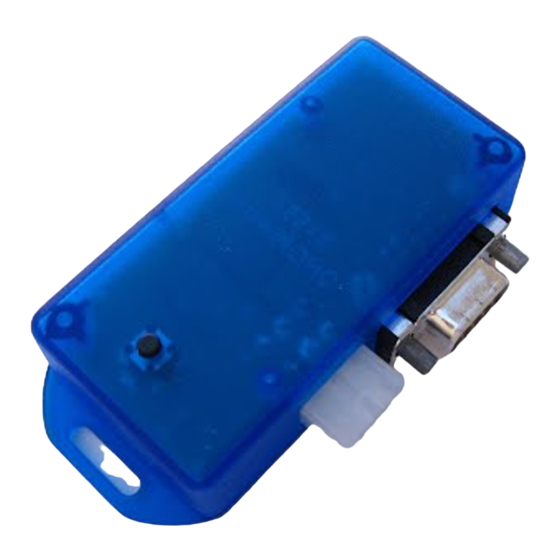
- Page 2 Included in the WOT BOX kit: You will need: • WOT Box • Wire Strippers • Soldering Iron or Station • Wiring harness • Metric Socket Set • USB to Serial Converter for future • Sandpaper software upgrades • Heat Shrink (if more than is included • Ground lug • Zip ties in the kit is needed) • Electrical tape • Heat shrink tubing • Zip Ties (if more than is included in the kit is needed) • Razor Blade or Sharp Knife • Multimeter or Ohm Meter • RTV or Hot Glue (optional) Pin @ WOT Box Wire Pin @ Pin @ ...
- Page 3 Figure II: Installation Diagram ...
- Page 4 3) 1) Open the hood and disconnect the 12V battery negative. 2) Pick out a location to mount the WOT Box. The WOT Box must be installed inside the passenger compartment since it is not waterproof. Additionally, you will 4) want to make the WOT Box accessible to the driver, due to the fact that setting the 2‐step RPM will require holding down the clutch pedal while holding the button on the WOT Box. Tape the WOT Box connector to this location. 3) Remove the passenger side plastic door sill/threshold cover (no tools required), remove the push pin, and then remove plastic passenger kick 5) panel. 4) Remove the 3 screws holding the bracket underneath the kick panel. 5) Loosen the connector securing bolt, and unplug the PCM connector ...
- Page 5 6) Remove the connector backshell by 6) unlocking the 4 securing tabs. Route the BLUE and YELLOW wires to this location, using zip ties to secure along the way. 7) Splice the BLUE WOT Box wire into the GRAY/WHITE wire at pin #89, making sure that the connectivity of the original wire is maintained. The second picture shows where pins #26 and #104 are for reference. 8) Splice the YELLOW WOT Box wire into the DARK BLUE wire at pin #21, making sure that the connectivity of the original wire is maintained. 9) Snap the backshell back onto the connector and connect it back to the PCM. Wait to remount the bracket and plastic trim until after testing. 10) 10) Under the drivers’ side dashboard, find the Cruise Control Clutch Switch. Remove the connector for ...
- Page 6 11) Route the GREEN WOT Box wire to 11) this location, using zip‐ties to secure along the way, and splice the GREEN WOT Box Wire into the PIN#1 (BOTTOM PIN, TOWARDS REAR OF VEHICLE) LIGHT GREEN wire, making sure that the original connectivity of the wire is maintained. 13) Locate a harness pass‐through on 12) Locate a good chassis ground point the firewall accessible from the near where you plan on installing passenger compartment. Some of the WOT Box. Try to keep the wire these are grommets that have run as short as possible. It should be enough room for extra wires to be under 2’ away, if possible. Next, cut passed through next to the existing the 18 AWG BLACK wire from the harness. Some have a tightly fitting WOT Box to length. Strip the wire skirt that the harness passes through that does not allow for and solidly crimp on the provided extra wires. If yours is the second, ground lug connection. Solder the carefully poke a new hole in the skirt ground wire to the ground lug. using a sharp object, such as a Connect this ground lug to the screwdriver. Be careful not to chassis. Make sure the metal where damage other wires already in the you attach the ground lug is clean, grommet, and make sure that the unpainted and free of rust. Use sand hole is only large enough for the RED/ORANGE pair from the WOT ...
- Page 7 14) Locate the C133 connector in the passenger side rear of the engine compartment, unscrew the 10mm bolt, unplug it, and find the big RED wire at pin #34. Route the RED/ORANGE WOT box pair to this location, using zip ties to secure along the way. 15) Making sure to leave enough room to connect on both sides, cut the red wire. 16) Split about 3” of the RED/ORANGE WOT box pair apart. Connect the RED WOT box wire to the side of the RED wire going to the C133 connector, and the BLACK WOT box wire to the side of the RED wire going into the loom and to the coils. 17) Remove the tape securing the WOT box connector. Plug in the WOT box, and mount securely. 18) Replace any components removed for convenience during the install, reconnect the 12V battery, and close the hood. The WOT Box install is complete‐ proceed to testing.
- Page 8 Troubleshooting ‐ Testing the WOT Box 1. Key on the car but do not start the engine. Press the gas pedal to the floor. You should see the LED on the WOT Box start to rapidly blink. If it does not, check your APP sensor signal connection (WOT Box BLUE wire). 2. Next, with the gas pedal still depressed, press the clutch pedal to the floor. You should see the LED on the WOT Box briefly go out, and then come back on solid for one second and then finally resume blinking rapidly. If you do not see this, check your Clutch Pedal Position Switch signal connection (WOT Box GREEN wire). 3. Next, start the engine. Quickly press the gas pedal to the floor and immediately step on the clutch. You should hear the engine start to rev up, stumble for a short period while the ignition is cut, then return back on and continue revving. Remove your foot from the gas before you hit the rev limiter. The 2‐step will not engage if the gas is depressed before the clutch. This is normal. If the engine does not stumble or pause when the LED turns out, then check the RED/ORANGE paired wire. Verify that the RED and ORANGE 16 AWG wires are wired facing the proper way. If they are reversed, the ignition cut will not work. 4. Lastly, test the 2‐Step. Press the clutch pedal down and then quickly press the gas pedal all the way down. The gas pedal must be floored for the 2‐step to engage. The engine should rev up to the desired RPM and hold. If it does not, be sure to remove your foot from the gas before you hit the rev limiter. If the 2‐step does not work, check the WOT Box YELLOW wire. 5. The WOT Box Graphical User Interface has some inherent troubleshooting capability. If you have access to a laptop, it may be useful for you to download the GUI at www.n2mb.com/wotboxsoftware and follow the instructions there. Usage To use the WOT Shift feature, keep your foot fully on the gas and shift quickly using the clutch. Keep the gas fully depressed through the shift. The WOT Box will detect the clutch switch signal and briefly cut the ignition to enable an effortless shift. To use the 2‐Step feature, fully depress the clutch. Next, fully depress the gas pedal to the floor. The engine will rev up and hold the RPM that you have set. Quickly release the clutch while leaving the gas fully depressed to launch the car. Programming The WOT Box comes preset for an automatic WOT Shift kill time. This means that the WOT Box will automatically adjust the kill time to your shift time, up to a maximum of 350 ms. If you would like manual control over the WOT Shift kill time, start the car and hold down the button ...
- Page 9 feature and setting 1 blink will set the automatic kill time mode. When you have reached the number of blinks that match your desired setting, simply let go of the button. To confirm, the WOT Box will blink back out the setting you entered. The WOT Box comes preset for a 2‐step RPM of 4000. To set the 2‐Step RPM, repeat the same procedure described above, but keep the clutch down during the entire operation. This will signify to the WOT Box that you want to set the 2‐step RPM and not the WOT Shift kill time. Use the second chart provided below to match up the desired RPM with the number of blinks. Setting 0 blinks will disable the 2‐Step feature. Ignition Cut Time Chart ‐ Set with the clutch UP Ignition Cut Ignition Cut Ignition Cut Ignition Cut Blinks Blinks Blinks Blinks (ms) (ms) (ms) (ms) 0 Disabled 6 125 18 425 1 Auto (default) 7 150 19 450 2 25 8 175 20 475 3 50 ...
- Page 10 CONGRATULATIONS! You have successfully installed the N2MB WOT BOX! N2MB Racing Limited Warranty N2MB Racing warrants that all of its products are free from defects in material and workmanship for a period of 1 year from the date of purchase. If an N2MB product is found to be defective within this period, N2MB Racing will repair or replace the product. The choice between these two methods of remedy is made at the sole discretion of N2MB Racing. This shall constitute the sole remedy of the purchaser and the sole liability of N2MB Racing to the extent permitted by law. This warranty is exclusive and in lieu of all other warranties or representations whether expressed or implied. This warranty is limited to the repair or replacement of the N2MB Racing product, and shall never exceed the purchase price of the N2MB Racing product. N2MB shall not be responsible for special or consequential damage or costs incurred as a result of the failure or use of the N2MB Racing Product except as required by law. Unauthorized alteration or repair of N2MB Racing products will void this warranty if the alteration or repair is found to have caused the N2MB Racing product to fail. In the event that a product is warranted, the purchaser shall be responsible for any and all shipping costs. N2MB Racing reserves the right to improve its products at any time and is at no time responsible for exchange or upgrade of products that were manufactured previously. ...
Need help?
Do you have a question about the WOT Box and is the answer not in the manual?
Questions and answers