Table of Contents
Advertisement
Advertisement
Table of Contents

Related Manuals for Vari Hurricane F-700

Summary of Contents for Vari Hurricane F-700
- Page 1 Mulcher Hurricane F-700 Instructions for use 2007...
- Page 2 F-700...
- Page 3 F-700 Text and illustrations c 2004 VARI,a.s. Publication No. VL-094-2004 Year on the front page is the year of Manual printing...
-
Page 4: Table Of Contents
F-700 Contents Basic information ....................... 5 Foreword ..........................6 Basic warnings ......................6 Operation safety ......................... 7 Safety regulations ....................... 7 Declared noise and vibration values................8 Safety pictographs ...................... 8 Use, technical specifications and technical description of the machine ......10 Machine use...................... -
Page 5: Basic Information
Fill in the following data concerning your machine. The data are important for ordering spare parts. It is advised to have a spare copy of this page with all data on the machine purchase for the case of loss or theft of the original record. VARI, a.s. ordering number 4165 Model F-700... -
Page 6: Foreword
,a.s. as a system of gardening, farming, small agricultural and communal technology. Hurricane F-700 mulcher is designed to meet the most exacting requirements of professional use. High-performance engine with a patent-protected edge on the cutting blade guarantee a problem-free mowing of different stand types. -
Page 7: Operation Safety
F-700 3 Operation safety 3.1 Safety regulations This international safety symbol indicates important messages concerning safety. When you see the symbol, be aware of a possible injury threatening to you or to other persons and read the following instructions carefully. The machine operator must be over 18 years of age. -
Page 8: Declared Noise And Vibration Values
All kinds of the machine repair, adjustment, lubrication and cleaning are to be made with the machine switched off and spark plug cable disconnected. 3.2 Declared noise and vibration values Hurricane F-700 with engine 89,0+1,0 dB = 98 dB = 2,5+1,3 m.s... - Page 9 F-700...
-
Page 10: Use, Technical Specifications And Technical Description Of The Machine
Snow plough ASR-700, snow chains, braked seat (sulky) AV-700. Note: The above attachments are sold separately. Ask your dealer to inform you about the term of their market introduction. 4.3 Technical specifications Hurricane F-700 Unit Value Length (incl. handlebars) 2037 Width Height (incl. -
Page 11: Instructions For Use
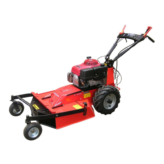
F-700 Figure 1: Mulcher Hurricane F-700 Gear shifting lever Blade drive lever Accelerator lever Cutting height adjustment lever Wheel drive clutch lever Engine starter grip Handlebars Blade casing Lever for side adjustment Front lift casing of handlebars Tightening nut for... - Page 12 F-700 5. Fasten the gear shifting lever (7) by means of 3 bolts M6x50 (8), 3 flat washers (9) and 3 self-locking nuts M6 (10) from the left to the lever holder on the bottom part of handlebars. The bolt with the washer should be mounted from the right. 6.
-
Page 13: Adjustment Of Handlebars
F-700 Plastic tape Washer Handlebars Tightening nut Gear Spring (2 pcs) shifting lever Turntable Washer Bolt Bolt Flat washer Self-locking nut Bolt Bumper assembly Unscrew 4 bolts M8x20 holding the handlebars holder Put the bumper on the handlebars holder and screw the on the machine chassis. -
Page 14: Putting Into Operation
F-700 In order to lessen the machine size e.g. for transport in a car, the handlebars should be either tilted forward over the engine or lowered into horizontal position and then turned clockwise by 180°. Bowden cables must be watched not to get tensioned somewhere on the machine construction. -
Page 15: Machine Travel Forward And Back
F-700 Starting of the cutting blade is accompanied with a partial V-belt slippage and with the accompanying phenomena such as whistling, rattling, etc. The phenomenon usually disappears after the belt has run in. 4. After the cutting blade starts turning, press the lever completely to the handrail and hold it firm. -
Page 16: Machine Stop
F-700 Note: All four main positions of engine speed adjustment lever are arrested by means of a simple system (stamp/projection) in the lever body. 5.6 Machine stop 5.6.1 Stopping on the plain If you wish to stop the machine travel, release the lever on the left handlebar grip. The machine will stop moving but the blade will still turn. -
Page 17: Adjustment Of Cutting Height
F-700 5.7.1 Adjustment of cutting height Adjustment of cutting height is affected by several important factors: • stand height and density • plant species prevailing in the stand • machine travel speed • cutting width • surface unevenness There is a general rule that the higher value of above mentioned factors, the greater height of guide wheels and cutting blade height adjustment above the surface. -
Page 18: The Way Of Stand Cutting
F-700 Figure 6: Travel speed choice Maximum speed. Meant exclusively for the machine Gear change transportation lever. Maximum working speed. Low-height or low-density stand . Good for flat and even terrains. Arrow Medium working speed. Medium-height and high-density stands. Good for mild slopes. Minimum working speed. -
Page 19: Cutting On Slopes
F-700 Tilt the machine always only backwards onto the handlebars. Be very careful while moving under the lifted machine! Secure the machine against its spontaneous motion! Be very careful while cleaning the space under the cutting blade cover. Cutting edges of the blades are sharp. You should wear protective gloves or use a suitable piece of branch etc. -
Page 20: Cutting Of High Grass Stands
F-700 5.7.7 Cutting of high grass stands This machine can also be used for cutting high grass stands without crushing. Herbage can be then used both for drying and as green fodder. Note: with respect to the cutting method, the proportion of crushed plants is higher than in other methods more friendly to plants. -
Page 21: Tightening Of Bolted Connections
F-700 Figure 9: Other lubrication points 6.2 Tightening of bolted connections Regularly check the tightening of all Figure 10: Blade clamping detail important bolted connections. Always check the tightening of bolts fastening the blade to the blade holder and the blade holder to the shaft prior to any machine use. -
Page 22: Replacement Of V-Belts And Adjustment Of Tension Pulleys
F-700 c) Mount the blade and the blade holder back onto the blade shaft in a reverse order of operations. Central bolt M10x1x25 has a fine thread and therefore it must not be mistaken for the side bolts whose threads are normal! It is always necessary to use the new spring washers (see the spare part list). -
Page 23: Adjustment Of Tension Pulleys
F-700 The procedure of replacing V-belts is as follows: a) Drain petrol from the engine tank. Remove the plastic ball from the accelerator lever. Dismount the accelerator lever from the handlebars crossbar. Bowden cable should never be dismounted from the control on the engine! Then dismount (or fold back) the handlebars holder (4x bolt M8) together with the handlebars. -
Page 24: Setting Up Pulley Wires, Blade Brake
F-700 Figure 12: Adjustment of tension pulleys Guide laminations Blade drive Driving belt pulley (on engine) Driven belt pulley of the blade Tension pulley V-belt Wheel drive Tension pulley Driving belt pulley (on engine) Driven belt pulley V-belt of the wheel drive 6.5 Setting up pulley wires, blade brake In order to guarantee low operating forces on levers which control the drive switching, it is advisable to lubricate the wires in Bowden cables at least 2x during the season with some... -
Page 25: Adjustment Of The Automatic Brake
F-700 Figure 13: Bowden cables and adjustment bolts Bowden No. Automatic Blade drive Arrestment of Wheel drive Description Gear shifting Blade brake brake pulley guide wheels clutch Nut of automatic brake 6.6 Adjustment of the automatic brake The automatic brake is activated by releasing the wheel drive clutch lever on the left side of handlebars. -
Page 26: The Table Of Service Operations
F-700 6.7 The table of service operations Operation During season After season Engine oil check prior to any use Engine air filter check prior to any use Blade check for clamping and intactness prior to any use, ** Check of the condition of V-belts as required inspection, *** Check of the function of automatic brake... -
Page 27: Machine Storage
6. All components should be ordered in the nearest service shop or at your dealer’s. In the case of any confusions concerning the spare parts or technical issues, the VARI, a.s. commercial, customer-service or technical departments are prepared to answer all your... -
Page 28: Contact To Manufacturer
F-700 8 Contact to manufacturer VARI, a.s. Telephone: (+420) 325 607 111 Opolanská 350 Fax: (+420) 325 607 264 Libice nad Cidlinou (+420) 325 637 550 CZECH REPUBLIC E-mail: vari@vari.cz 289 07 internet: http://www.vari.cz/ 9 The list of parts If not mentioned otherwise, the tables of spare parts hold for all models of the machine. - Page 29 F-700...
- Page 30 F-700 Frame and blade drive Pos. Description Drawing-Standard Order.no. Quantity 100 MULCHER CHASSIS 22 9 1536 059 184 115 101 BRAKE SHOE 22 9 1664 024 189 014 102 DRIVEN BELT PULLEY OF BLADE 3203325072 184 038 103 WHEEL DRIVE CLUTCH PULLEY SEE SEPARATE PART LIST 104 BLADE DRIVE PULLEY SEE SEPARATE PART LIST...
- Page 31 F-700...
- Page 32 F-700 Gearbox, handlebars holder Pos. Description Drawing-Standard Order.no. Quantity 200 LEVER DC10 1LC0717001 184 534 201 DRIVEN BELT PULLEY OF WHEEL DRIVE 22 9 3325 039 184 041 202 GEAR SHIFTING LEVER WELDMENT 22 9 3832 008 184 045 203 HANDLEBARS HOLDER - PREASSEMBLY SEE SEPARATE PART LIST 204 HANDLEBARS F-700 ASSEMBLY SEE SEPARATE PART LIST...
- Page 33 F-700...
- Page 34 F-700 Wheels, guide wheels, covers Pos. Description Drawing-Standard Order.no. Quantity 300 HINGE 905500531 P 184 612 302 GUIDE WHEELS F-700 SEE SEPARATE PART LIST 303 LEFT WHEEL F-700 SEE SEPARATE PART LIST 304 RIGHT WHEEL F-700 SEE SEPARATE PART LIST 305 MUD GUARD 32 0 8530 038 184 043...
- Page 35 F-700...
- Page 36 F-700 Engine HONDA GXV 340 Pos. Description Drawing-Standard Order.no. Quantity 400 INTERMEDIATE FLANGE 22 9 2752 020 184 050 401 DRIVING BELT PULLEY F-700 22 9 3325 035 184 048 402 ENGINE PLATE F-700 WELDMENT 22 9 8032 054 184 049 403 COMPLETE COVER OF MULCHER BELT 22 9 8545 039 184 020 405 KEY 6.3e7x40...
- Page 37 F-700 Handlebars holder Pos. Description Drawing-Standard Order.no. Quantity 1 PIVOT 3209311103 192 007 2 PIN 3x18 CSN022156 127 504 3 SPRING 1.25x11x25x28x8.5 3209746004 124 500 4 NUT M10 CSN021492.25 195 527 5 WASHER 10,5 CSN021702.15 189 567 6 HANDLEBARS HOLDER F-700 2298045064 184 058 7 SWIVEL HOLDER WELDMENT 2298053013...
- Page 38 F-700 Guide wheels Pos. Description Drawing-Standard Order.no. Quantity 1 GUIDE WHEELS FRAME F-700 22 9 1646 039 184 121 2 LEFT WHEEL HINGE 22 9 1646 036 184 104 3 RIGHT WHEEL HINGE 22 9 1646 037 184 105 4 SLIDE WASHER 32 0 9220 229 182 039 5 FLEXIBLE SPLIT PIN...
- Page 39 F-700...
- Page 40 F-700 Handlebars Pos. Description Drawing-Standard Order.no. Quantity 1 RED KNOB 1AC02040 184 519 2 BOWDEN CABLE OF ROLLER F-700 22 9 8074 050 184 502 3 BOWDEN CABLE OF BRAKE F-700 22 9 8074 051 184 501 4 BOWDEN CABLE OF CLUTCH F-700 22 9 8074 053 184 503 5 BOWDEN CABLE OF WHEEL ARRESTMENT F-700 22 9 8074 054...
- Page 41 F-700 Wheel left, right Pos. Description Drawing-Standard Order.no. Quantity 1 DRIVER OF DIFFERENTIAL 2291625029 184 059 2 DRIVER PIN 3209311165 184 057 3 SPRING 1.25x11.25x28x8.5 3209746004 124 500 4 WHEEL 16x6,5-8 F-700 LEFT 62291770037 184 526 5 WHEEL 16x6,5-8 F-700 RIGHT 62291770038 184 525 6 PIN 3x18 CSN022156...
- Page 42 F-700 Blade drive pulley Pos. Description Drawing-Standard Order.no. Quantity 1 PULLEY ARM 22 9 3330 021 184 069 2 PULLEY FOR BELT X17 632 0 3325 069 184 579 3 BEARING 6300 2RS 189 585 4 RETAINING RING 35 ČSN 02 2931 126 503 5 RETAINING RING 10 ČSN 02 2930...
-
Page 43: Letter Of Guarantee
Warranty period for the product and accessories supplied with the product is 24 months from the date of sale to the purchaser if not stated otherwise in the “Service Manual for VARI Machines and Systems Equipped with HONDA Engines“. Time from the enforcement of liability for defects to the date when the user was obliged to take over the thing after the end of repair is not included in the warranty period. - Page 44 F-700 Warranty inspection 1 Warranty inspection 1 Date: ………………………………………Person in charge:………………………………………………… Machine model………………………… Serial No.:…………………………… Service shop stamp and signature Warranty inspection 2 Warranty inspection 2 Date:………………………………………Person in charge:………………………………………………… Machine model………………………… Serial No.:…………………………… Service shop stamp and signature Warranty service Warranty service Date of complaint delivery:………………………………………………………………………………………...
Need help?
Do you have a question about the Hurricane F-700 and is the answer not in the manual?
Questions and answers