Sign In
Upload
Download
Table of Contents
Contents
Add to my manuals
Delete from my manuals
Share
URL of this page:
HTML Link:
Bookmark this page
Add
Manual will be automatically added to "My Manuals"
Print this page
×
Bookmark added
×
Added to my manuals
Manuals
Brands
Merlin Gerin Manuals
Controller
Varlogic NR6
User manual
Merlin Gerin Varlogic NR6 User Manual
Power factor controller
Hide thumbs
1
Table Of Contents
2
3
4
5
6
7
8
9
10
11
12
13
14
15
16
17
18
19
20
21
22
23
24
25
26
27
28
29
30
31
32
page
of
32
Go
/
32
Contents
Table of Contents
Bookmarks
Table of Contents
Table of Contents
1 General
Safety
Description
2 Installation
3 Display
4 Start-Up Procedure
5 Menu Operations
General
Main Menu
Bank Pre-Configuration
Commissioning
Auto Setup of Parameters
Manual Setup of Parameters
Measurement Menu
Parameter Update
Alarms Menu
Maintenance Menu
6 Miscellaneous
Stepping Programs
Manual Calculation of Response Value
High Voltage Use of NR6/NR12
7 Glossary
8 Technical Specifications
Advertisement
Quick Links
1
General
2
Installation
3
Start-Up Procedure
4
Main Menu
5
Auto Setup of Parameters
6
Manual Setup of Parameters
7
Alarms Menu
8
Maintenance Menu
Download this manual
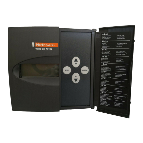
Varlogic NR6, NR12
Power factor controller
User manual
Table of
Contents
Previous
Page
Next
Page
1
2
3
4
5
Advertisement
Table of Contents
Need help?
Do you have a question about the Varlogic NR6 and is the answer not in the manual?
Ask a question
Questions and answers
Related Manuals for Merlin Gerin Varlogic NR6
Controller Merlin Gerin Varlogic NR12 User Manual
Power factor controller (32 pages)
Controller Merlin Gerin itm 4c 6e User Manual
(4 pages)
This manual is also suitable for:
Varlogic nr12
Table of Contents
Save PDF
Print
Rename the bookmark
Delete bookmark?
Delete from my manuals?
Login
Sign In
OR
Sign in with Facebook
Sign in with Google
Upload manual
Upload from disk
Upload from URL


Need help?
Do you have a question about the Varlogic NR6 and is the answer not in the manual?
Questions and answers