
Related Manuals for Vingtor Stentofon VPA-120


Summary of Contents for Vingtor Stentofon VPA-120
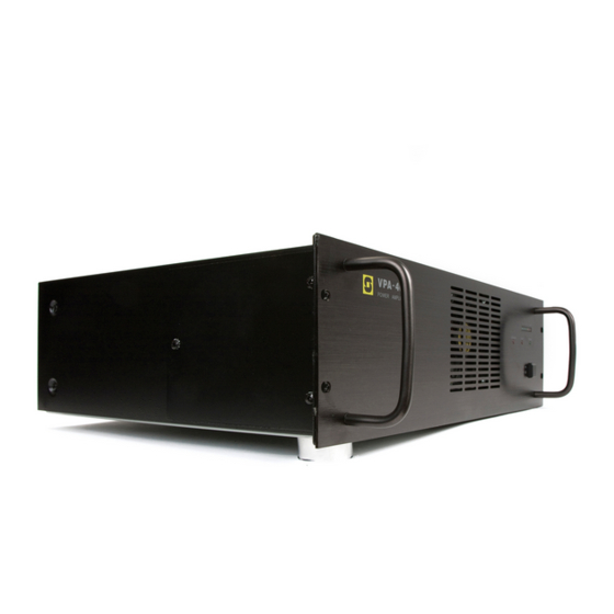
- Page 1 VPA PUBLIC ADDRESS AMPLIFIERS VPA-120 / 240 / 400 A100K10876 INSTALLATION & SERVICE MANUAL...
-
Page 2: Table Of Contents
T a b l e o f C o n t e n t s 1 INTRODUCTION................3 1.1 About this document..............3 1.2 Equipment covered by this document ........3 1.3 Rules and regulations..............3 1.4 Publication log ................3 2 CONNECTORS AND CONTROLS ........... -
Page 3: Introduction
User and Installation Manual 16 911 007. This document is aimed at Service personnel Installers 1.2 Equipment covered by this document Public Address amplifiers VPA-120 120 W VPA-240 240 W VPA-400 400 W NOTE! The amplifiers are delivered for 230 VAC as standard. -
Page 4: Connectors And Controls
The connectors and controls of all three amplifier types are identical except for the maximum rated output power. 2.1 Front and rear panels 1 – Overload warning VPA-120 POWER AMPLIFIER 2 – Fault warning +1dB 3 – VU-meter, -18, -10, -6, 0, +1dB... -
Page 5: Signal Inputs
The amplifier must be grounded either through the earth leg in the mains plug or by a 1.5 mm wire between the amplifier’s ground terminal Warning and proven good grounding point, e.g. the rack frame. This appatatus must be earthed 2.4 Signal inputs There are two inputs with 3-pin XLR connectors. -
Page 6: Installation
INSTALLATION 3.1 Unpacking The amplifier was thoroughly checked at the factory. Inspect the amplifier, the enclosed parts and the shipping container for signs of improper handling during shipment. If you find any damage, immediately contact the dealer from whom you purchased the unit to make a claim. 3.2 Mounting The amplifier should be installed in a technical room with adequate ventilation, a recommended temperature between 18-25... -
Page 7: Mains Power
Cable layout Do not run the installation cable from microphone and alarm panels parallel to, or to near the cables for loudspeakers or power cables. The screens must be interconnected in junction boxes and grounded in the VPA main unit only. It is good practice to have separate conducts for each type of signal cabling. -
Page 8: Input Connection
3.3.4 Input connection SLAVE The CALL and BMG line inputs are balanced, accepting 0.5 -1.5 Vrms CALL signal over 47 Kohm. The input level is adjustable +/- 6 dB. – 6 The signal source is connected between pin 2 and 3, the wire screen is connected to pin 1. -
Page 9: Optional Connections
3.3.6 Optional connections Monitor loudspeaker MONITOR FAULT RELAY DC OUT REMOTE PRIORITY Mount an 8 ohm loudspeaker rated at minimum 1.5 W close to the MONITOR amplifier to monitor entertainment and call channels. Connect the loudspeaker wires to the MONITOR terminals marked 800 mA COM and 8Ω. -
Page 10: Startup And Operation
STARTUP AND OPERATION 4.1 System check-out 4.1.1 Preparations Be sure all connections are properly made according to chapter 3. Turn all volume controls to min. position (CCW). Connect the power cord to the mains outlet. Turn the mains switch ON and check that the POWER LED is on. The FAULT and OVERLOAD LEDs should not be lit. -
Page 11: Speaker Line Fault Detection
4.1.3 Speaker line fault detection A 23 kHz tone is continuously transmitted on the loudspeaker line to detect faulty lines. The switch on the upper left board (AMP-2) inside the cabinet should be ON to enable this function. If the FAULT LED on the front is on without any obvious reasons, or the first VU-meter LED is lit without any signal source, the pilot tone level may need adjustment. -
Page 12: Service
SERVICE 5.1 Service information All service on this unit should be performed by qualified service technicians only. Contact your local VINGTOR / STEENHANS dealer or their representative for service. Schematic diagrams, component layout, spare part lists and other service information are available from Zenitel Marine. WARNING! Always disconnect the mains cable and 24 VDC power before opening the cabinet to avoid electrical chock hazard and possible damage to the equipment... -
Page 13: Fuse Replacement
A blown fuse normally indicates a malfunction of the amplifier. Check for overload or other suspicious indications of excessive current drain. Always replace with fuse of same type and value. At repeated fuse blows, contact qualified service personnel. FUSE MAINS VPA-120 VPA-240 VPA-400 115 V 5x20 mm 10 A... -
Page 14: Technical Data
5.4 Technical data VINGTOR VPA series TYPE CONDITION VPA-120 VPA-240 VPA-400 Material Front Black anodized aluminum Dimensions W x H x D 482 x 133 x 420 mm Mounting Marine version in 19” rack Weight 18.2 kg 21.2 kg 27.4 kg... -
Page 15: Apendix
APENDIX 6.1 Block diagram A100K10876 Installation and Service Manual Page 15 VPA Amplifiers... -
Page 16: Schematic Diagram, Amplifier
6.2 Schematic diagram, Amplifier Page 16 Installation and Service Manual A100K10876 VPA Amplifiers... -
Page 17: Schematic Diagram, Booster
6.3 Schematic diagram, Booster A100K10876 Installation and Service Manual Page 17 VPA Amplifiers... -
Page 18: Component Numbers, Amplifier
6.4 Component numbers, Amplifier Page 18 Installation and Service Manual A100K10876 VPA Amplifiers... -
Page 19: Component Values, Amplifier
6.5 Component values, Amplifier A100K10876 Installation and Service Manual Page 19 VPA Amplifiers... -
Page 20: Component Numbers, Booster
6.6 Component numbers, Booster Page 20 Installation and Service Manual A100K10876 VPA Amplifiers... -
Page 21: Component Values, Booster
6.7 Component values, Booster A100K10876 Installation and Service Manual Page 21 VPA Amplifiers... - Page 22 www.vingtor.com Zenitel Norway AS DOC NO. A100K10876 support@vingtor.com STENTOFON and VINGTOR products are developed and marketed by Zenitel Norway AS. The company’s Quality Assurance System is certified to meet the requirements in NS-EN ISO 9001:2008. Zenitel Norway AS reserves the right to modify designs and alter specifications without prior notice, in pursuance of a policy of continuous improvement.
Need help?
Do you have a question about the VPA-120 and is the answer not in the manual?
Questions and answers
what is the input audio signal voltage for amplifier