
Related Manuals for Bespoke Infinity


Summary of Contents for Bespoke Infinity
- Page 1 INSTALLATION Infinity Stairlift Rail MANUAL Carriage Seat Huddersfield • England...
-
Page 2: Introduction
INTRODUCTION The information contained within this manual has been designed for use by Bespoke approved engineers who have received the appropriate product training in the following categories, 1. Product installation. 2. Testing and commissioning. lt is also assumed that the person... -
Page 3: Table Of Contents
CONTENTS Introduction 2 Contents 3 Rail Preparation and Fixing 4-9 Carriage Preparation and Assembly 10-30 Calibrate and Program the Stairlift 31-35 Troubleshooting 36-39 Wiring Diagrams 40 Certificate of Conformity 41 Demonstration and Handover 42 Installation Tools 43... - Page 4 RAIL PREPARATION Remove packaging and protective wrapping from rail sections. Position rail sections on staircase as per Stairlift Specifications 2108.8 Model BS 101 Installation Drawing. Type Base/Stanchion Base Stanchion Type Total Height Number Height Length Handing Right 205 ABF 312.87 Swivel Manual 499.87...
- Page 5 RAIL PREPARATION Thread 2-core cable through lower tube of each section of rail, working from top to bottom. Ensure a minimum of 150mm of cable at each end.
- Page 6 RAIL FIXING Assemble rail joints together working from bottom to top of stairs. Note: Offer top tubes first. Apply grease to male part of joint. Pins should be flush with stair side of rail. Fit and tighten joint clamps Using the installation drawing details: Check top and bottom rail heights over the corresponding steps.
- Page 7 RAIL FIXING Secure plates to the staircase by the following method: Loosen grub screws on leg collar Fix foot-plate with 3 screws (Figure 4) Tighten screw to leg. Repeat for each leg. The following fixings are recommended: Timber Staircase - 3 x 50mm screws. Concrete Staircase -3 x 50mm screws &...
- Page 8 RAIL FIXING Finally ensure all rail dimensions are in accordance with the rail installation drawing. Carry out any final adjustment to the bases as required using the 3 x Grub Screws then tighten once the rail position is correct.
- Page 9 MOUNTING THE CHARGER Find a suitable power supply as close as possible to either the top or bottom of the stairs. Mount the charger in a suitable position near the power supply using the screws supplied. Please ensure the charger is mounted level and secure.
- Page 10 CARRIAGE PREPARATION...
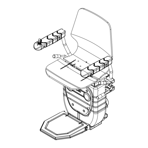
- Page 11 CARRIAGE PREPARATION Unwrap the pre-assembled carriage and footrest, seat & arm assembly and EITHER a manual swivel or powered swivel boss assembly. CARRIAGE & FOOTREST SEAT & ARMREST ASSEMBLY MANUAL SWIVEL POWERED SWIVEL BOSS ASSEMBLY BOSS ASSEMBLY...
- Page 12 CARRIAGE PREPARATION Once the carriage is removed from the box insert the long loading bar into the top skate.(Fig 1) Loading strap Insert the small cone into the bottom rail tube. Fig 1 (Loading bar & cone are part of the Loading Bar separate installation kit.) Fig 2...
- Page 13 CONTROL CABLE INSTALLATION LH Control LH Swivel RH Control RH Swivel LH Control RH Swivel RH Control LH Swivel...
- Page 14 INSTALLATION OF THE POWERED SWIVEL UNIT Powered Swivel Unit Powered Swivel Board M5 x4 M8 x8 CABLE...
- Page 15 INSTALLATION OF THE POWERED SWIVEL UNIT Powered Swivel Unit Powered Swivel Board...
- Page 16 INSTALLATION OF THE POWERED SWIVEL UNIT...
- Page 17 INSTALLATION OF THE POWERED SWIVEL UNIT...
- Page 18 INSTALLATION OF THE MANUAL SWIVEL LEVER In the Box...
- Page 19 INSTALLATION OF THE MANUAL SWIVEL LEVER...
- Page 20 INSTALLATION OF THE MANUAL SWIVEL LEVER...
- Page 21 INSTALLATION OF THE MANUAL SWIVEL UNIT Manual Swivel Unit M8 x8 M5 x4...
- Page 22 INSTALLATION OF THE MANUAL SWIVEL UNIT...
- Page 23 INSTALLATION OF THE MANUAL SWIVEL UNIT Connect the Swivel Micro-switch as shown in the detail below.
- Page 24 INSTALLATION OF THE MANUAL SWIVEL UNIT...
- Page 25 CARRIAGE ASSEMBLY Fig 1 INSTALLING THE BATTERIES Remove the front panel by removing the 4 screws. The battery housing is easily accessible behind the front panel. Install the batteries as shown in Fig 1. Replace the front panel. FUSE...
- Page 26 CARRIAGE ASSEMBLY RESET THE CHAIR On the main board, hold down button 1, switch on the main switch. Keep button 1 pressed down until an audible beep is heard. BEEP...
- Page 27 PROGRAM THE REMOTE CONTROLS The steps below must be carefully followed to ensure the remote controls are correctly programmed to the stairlift. 1 - Turn on the lift’s main switch PRESS micro-switch 3 ONCE PRESS ONCE 1 2 3 2 - IMMEDIATELY Press and hold either directional button on the remote.
- Page 28 CARRIAGE ASSEMBLY MOVE THE CARRIAGE DOWN THE RAIL (Fig 1) Using the temporary remote move the carriage down the rail to a position that is accessible. This will enable the seat and armrest component to be easily assembled. Switch off the carriage by the main switch and disconnect the temporary remote.
- Page 29 CARRIAGE ASSEMBLY CONNECT THE SEAT BASE WITH ARMS Fig 1 TO THE CARRIAGE Feed the joystick cable through the hole in the centre of the boss carriage (as illustrated in figure 1) and pass through to the front of the carriage. Connect the joystick connector cable to the PCB cable (as shown in figure 2).
- Page 30 CARRIAGE ASSEMBLY Mount the seat & armrests assembly to the swivel boss using 4x M8x40 Cap-head screws (use Locktight threadlocker)
- Page 31 INSTALL RAIL CHARGE POINTS Place the charging terminals at the top and bottom of the rail and connect to the 2 core cable as shown opposite. Install the final end stop brackets at the top and bottom of the rail, then turn on the charger.
- Page 32 CALIBRATE THE STAIRLIFT Your Stairlift should be delivered with the correct hand already configured but a simple check should be taken to ensure correct functionality. Open the access panel located on the right side panel of the stairlift to view the main board.
- Page 33 PROGRAMMING THE STAIRLIFT Fig 1 ATTENTION ENSURE THE CHARGER IS POWERED BEFORE BEGINNING TO PROGRAMME THE STAIRLIFT RESET THE STAIRLIFT AS SHOWN ON PAGE 18 Move the stairlift to its first terminal (Downstairs) Then stop the stairlift (Fig 1) the stairlift will automatically stop on Fig 2 STOP stop...
- Page 34 PROGRAMMING THE STAIRLIFT Finally move the stairlift upstairs to final STOP charging terminal Follow these steps when the stairlift is at its final charging terminal; stop • Switch off the stairlift. • Wait 10 seconds. • Switch the stairlift on •...
- Page 35 PROGRAMMING THE BEND SLOWING FUNCTION (Optional) Note: The Infinity Stairlift must be programmed as normal; should slowing be required please use the following steps. To slow The Infinity Stairlift when travelling around the bends the unit 3.Move must be programmed the following way;...
-
Page 36: Troubleshooting
TROUBLESHOOTING... - Page 37 MANUAL OVERRIDE Manually insert the winding handle into the hole located on the left side of the carriage and locate the winding mechanism. Engage the winding mechanism and manually turn the handle. To release the over-speed governor (OSG) wind the stairlift in the upwards direction to release the OSG arm.
- Page 38 RESET THE OSG Run the lift upwards with the manual override, the OSG should come loose from the tube then. Make sure that the OSG is in neutral position again. The unit does not need re-programming DETAIL A SCALE 1 : 2...
- Page 39 THE AUDIBLE DIAGNOSTICS The Audible diagnostics feature that can inform the engineer of any problems that The Infinity Stairlift has encountered during installation or in BEEP general use. Depending on the problem The Infinity Stairlift emits a selection of loud beeps to indicate what...
-
Page 40: Wiring Diagrams
INFINITY WIRING DIAGRAM Mainswitch Groundbattery Black Battery Positive 30A Fuse Chargingpoint Brown Brown Swivelsensor Swivelsensor Mainframe Mainframe_2 Safety Right Safety Left Connect to Blue swivelsensor Orange Orange Blue Green Joystick Green Mainframe Joystick left Black nr.2 Extension Black armrest LED Ground sensor Black nr.3... -
Page 42: Demonstration And Handover
DEMONSTRATION AND HANDOVER when used, should only swivel in the up direction as a safety measure. • DEMONSTRATION On N0 occasion should the manual override function allow the user to • EXPLANATION swivel the chair in • USER SAFETY • USER BOOKLET the down direction. -
Page 43: Installation Tools
TOOLS AND EQUIPMENT INSTALLATION TOOLS 19) Magnetic angle finder 1) 2 ft (500mm) spirit level (approx) 2) Extension Bar 3/B” or W drive) 20) Digital Multi meter/Clamp meter 3) Tape Measure ~ 5 metres (must be capable of measuring DC 4) 6mm twist drill bit (15/16”) current at 30A for at least 5 seconds) 21) Nut runners - sizes: 5mm, 5) 8mm masonry drill bits... - Page 44 Infinity Stairlift Rail Carriage Seat Huddersfield • England...
Need help?
Do you have a question about the Infinity and is the answer not in the manual?
Questions and answers