Advertisement
Shock/Vibration Control Switches
Installation Instructions
Models: VS2, VS2C, VS2EX, VS2EXR, VS2EXRB and VS94
Please read the following instructions before installing. A visual inspection of this product for damage during shipping is recommended before
mounting. It is your responsibility to have a qualified person install the unit, and make sure installation conforms with NEC and local codes.
WARNING
BEFORE BEGINNING INSTALLATION OF THIS MURPHY PRODUCT
✔ ✔
Disconnect all electrical power to the machine.
✔ ✔
Make sure the machine cannot operate during installation.
✔ ✔
Follow all safety warnings of the machine manufacturer.
✔ ✔
Read and follow all installation instructions.
Description
The Murphy shock and vibration switches are available in a variety of
models for applications on machinery or equipment where excessive
vibration or shock can damage the equipment or otherwise poses a
threat to safe operation. A set of contacts is held in a latched position
through a mechanical latch and magnet mechanism. As the level of
vibration or shock increases an inertia mass exerts force against the
latch arm and forces it away from the magnetic latch causing the latch
arm to operate the contacts. Sensitivity is obtained by adjusting the
amount of the air gap between the magnet and the latch arm plate.
Applications include all types of rotating or reciprocating machinery
such as cooling fans, engines, pumps, compressors, pump jacks, etc.
Models
VS2: Base mount; non hazardous locations.
VS2C: C-clamp mount; non hazardous locations.
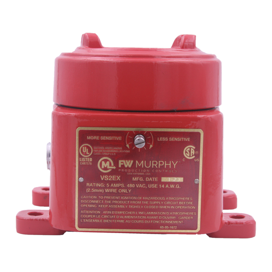
VS2EX: Explosion-proof; Class I, Div. 1,
Groups C and D.
VS2EXR: Explosion-proof with remote reset.
VS2EXRB: Explosion-proof; Class I, Div. 1, Group B
remote reset.
VS94: Base mount; non hazardous locations, NEMA 4X/IP66.
GENERAL INFORMATION
Remote Reset Feature (VS2EXR,
VS2EXRB and VS94 only)
Includes built-in electric solenoid which allows reset of tripped unit from a
remote location. Standard on VS2EXR and VS2EXRB. Optional on
VS94 (options listed below).
-R15: Remote reset for 115 VAC
-R24: Remote reset for 24 VDC
Time Delay Option (VS94 only)
Overrides trip operation on start-up. For VS94 series models, the delay
time is field-adjustable from 5 seconds up to 6-1/2 minutes with a 20-
turn potentiometer (15 seconds per turn approximately). Options listed
below:
-T15: Time delay for 115 VAC
-T24: Time delay for 24 VDC
Space Heater Options (VS94 only)
This optional space heater board prevents moisture from condensing
inside the VS94 Series case. Options listed below:
-H15: Space heater for 115 VAC
with
-H24: Space heater for 24 VDC
;
Warranty
A limited warranty on materials and workmanship is given with this FW
Murphy product. A copy of the warranty may be viewed or printed by going
to www.fwmurphy.com/support/warranty.htm
VS-7037N page 1 of 8
R
LISTED*
Model VS2EX
VS-7037N
Revised 04-05
Section 20
(00-02-0185)
Advertisement
Table of Contents

Related Manuals for Murphy VS2


Summary of Contents for Murphy VS2
-
Page 1: Installation Instructions
VS94: Base mount; non hazardous locations, NEMA 4X/IP66. A limited warranty on materials and workmanship is given with this FW Murphy product. A copy of the warranty may be viewed or printed by going to www.fwmurphy.com/support/warranty.htm VS-7037N page 1 of 8... - Page 2 DIMENSIONS VS2C 3 in. 4-3/4 in. 3 in. 4-3/4 in. (76 mm) (121 mm) (76 mm) (121 mm) Slotted Slotted Sensitivity Adjustment Sensitivity Reset Adjustment Push Reset 4-19/32 in. Button Push 5-7/16 in. (116 mm) Plug Button Weatherproof (138 mm) Strain Relief Bushing 5-1/8 in.
-
Page 3: Specifications
(C). should be thick enough to prevent induced acceleration/vibration upon the VS2 or VS94 Series. Typically 1/2 in. (13mm) thick plate is sufficient. See 3. The hardened set screw and nuts (D) are used to illustrations on page 5 for typical mounting locations. -
Page 4: All Models
The time is factory-set at the lowest setting (5 seconds approximately). To increase time, All models of the VS2 and VS94 Series cover a wide range of sensitivity. rotate the 20-turn pot clockwise as needed Each model is adjusted to the specific piece of machinery on which it is Turn to (15 seconds per turn approximately). -
Page 5: Typical Mounting Locations
TYPICAL MOUNTING LOCATIONS These are typical mounting locations for best operation. Other mountings are possible. NOTE: See Installation section on page 3. 2-Throw Balance-Opposed Compressor Pumping Unit Reset NOTE: If installing on cylinders, 2 vibration/shock Reset switches are recommended- 1 for each cylinder. Engine “Y”... -
Page 6: Internal Switches
INTERNAL SWITCHES VS2 and VS2C VS2EXR Remote Reset Terminal Sensitivity Adjustment Sensitivity Adjustment NO COM Ground Terminal SPDT Snap-Switch SPDT Switch Terminals VS2EXB and VS2EXRB VS2EX Remote Reset SPDT Snap-Switch Terminal Sensitivity Sensitivity Adjustment Adjustment NO COM NO COM NO COM... - Page 7 CD Ignition CD Ignition CD Ignition Resistor (100 Ω, 3 Watt) VS2, VS2C, VS2EX, VS2EXR, VS2EXRB and VS94 VS2, VS2C, VS2EX, VS2EXR, VS2EXRB and VS94 Typical Wiring Diagram for Electric Motors Typical Wiring Diagram for Distributor Ignition or Diesel Contacts shown...
-
Page 8: Service Parts
FW Murphy INDUSTRIAL PANEL DIVISION P.O. Box 470248 MURPHY DE MEXICO, S.A. DE C.V. P.O. Box 470248 Blvd. Antonio Rocha Cordero 300, Fracción del Aguaje Tulsa, Oklahoma 74147 USA Tulsa, Oklahoma 74147 USA San Luis Potosí, S.L.P.; México 78384...
Need help?
Do you have a question about the VS2 and is the answer not in the manual?
Questions and answers