Garmin G5 Install Manual & Pilot's Manual
Standalone
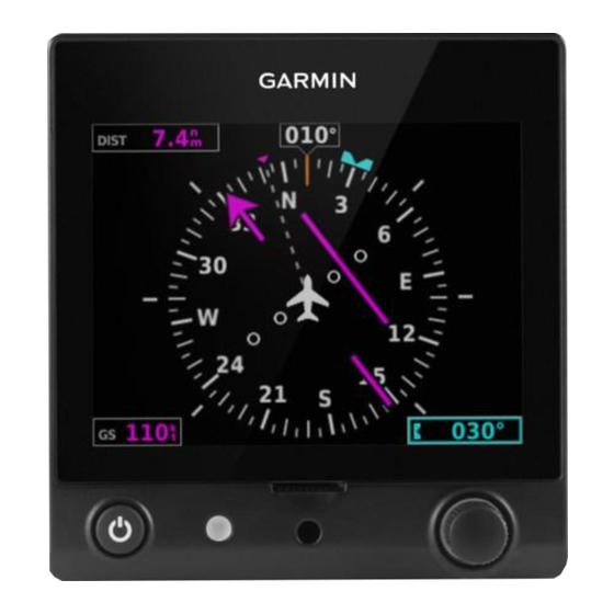
flight display or a fully integrated backup instrument for g3x systems
Hide thumbs
Also See for G5:
- Installation manual (285 pages) ,
- User manual (168 pages) ,
- Pilot's manual (96 pages)
Table of Contents
Advertisement
Advertisement
Table of Contents
Troubleshooting

Related Manuals for Garmin G5


Summary of Contents for Garmin G5
- Page 1 G5 Install Manual & Pilot's Guide...
- Page 2 Blank Page...
- Page 3 INSTALLATION MANUAL PILOT'S GUIDE APPENDIX INDEX...
- Page 4 Blank Page...
- Page 5 Garmin is a registered trademark of Garmin Ltd. or its subsidiaries. This trademark may not be ® used without the express permission of Garmin.
- Page 6 WARNING: To reduce the risk of unsafe operation, carefully review and understand all aspects of the G5 Install Manual & Pilot's Guide documentation and the Pilot’s Operating Handbook of the aircraft. Thoroughly practice basic operation prior to actual use.
- Page 7 FAA, FCC, and other applicable regulations. NOTE: The G5 may only be installed in type-certificated aircraft in accordance with Garmin STC SA01818WI. NOTE: The term LRU, as used throughout this manual is an abbreviation for Line Replaceable Unit.
- Page 8 Although unlikely, it may be possible for erroneous operation to occur without a fault indication shown by the G5. It is thus the responsibility of the pilot to detect such an occurrence by means of cross-checking with all redundant or correlated information available in the cockpit.
- Page 9 LICENSE AGREEMENT AND WARRANTY ontaCt armin Contact Garmin if you have any questions while using the G5. In the USA contact Garmin Product Support by phone: (913) 397-8200 or (800) 800-1020, Monday–Friday, 8 AM–5 PM Central Time; or go to www.garmin.com/support.
- Page 10 Greement BY USING THE G5, YOU AGREE TO BE BOUND BY THE TERMS AND CONDITIONS OF THE FOLLOWING SOFTWARE LICENSE AGREEMENT. PLEASE READ THIS AGREEMENT CAREFULLY. Garmin grants you a limited license to use the software embedded in this device (the “Software”) in binary executable form in the normal operation of the product.
- Page 11 Distributor warranties are only valid in the area of intended distribution. Devices purchased in the U.S. or Canada must be returned to the Garmin service center in the U.K., the U.S., Canada, or Taiwan for service.
- Page 12 April, 2016 Updates to Installation Manual section. September, 2016 Added interconnect drawings, various updates December, 2016 Added autopilot trim and speed annunciations. May, 2017 Added GMU 11 info, various updates Garmin G5 Install Manual & Pilot's Guide 190-02072-00 Rev. E...
-
Page 13: Table Of Contents
1.6.7 Unit ID (Strapping) ....................53 1.6.8 Splicing Signal Wires ....................54 1.7 G5 Interconnect Drawings ..................... 55 1.8 G5 Configuration and Post Installation Checkout ........... 63 1.8.1 Recommended Test Equipment ................. 64 1.8.2 Configuration Mode ....................64 1.8.3 Software Loading Procedure ..................65 1.8.4 Configuration Pages .................... - Page 14 1.9.5 Attitude failure Troubleshooting ................142 1.9.6 Heading Failure Troubleshooting (with GMU 11) ............. 143 1.9.7 G5 Data Logging ....................144 1.9.8 Sending Troubleshooting Data to Garmin ..............144 1.10 Maintenance ........................ 145 1.10.1 Inspections/Continued Airworthiness/Maintenance ..........145 1.10.2 Return to Service Information ................146 1.11 Performance Specifications/Licensing/Compliance ..........
- Page 15 2.9 Automatic Flight Control System (Optional) ............177 2.9.1 AFCS System Architecture ..................177 2.9.2 Control Wheel Steering (CWS) (Optional) ..............179 2.9.3 G5 AFCS Status Box ....................179 2.9.4 G5 AFCS Configuration................... 180 2.9.5 AFCS Operation ...................... 181 2.9.6 AFCS PRE-FLIGHT Actions (Standalone Installation) ..........182 2.9.7 AFCS Controls ......................
- Page 16 Table of Contents Blank Page Garmin G5 Install Manual & Pilot's Guide 190-02072-00 Rev. E...
-
Page 17: Section 1 Installation Manual
G3X systems via the CAN network. When installed as part of a G3X system, the G5 provides a redundant source of attitude and air data to the G3X displays, and additionally provides backup autopilot control allowing 190-02072-00 Rev. -
Page 18: Inventory Of Materials
All materials that are required/optional for the installation of the G5 are listed in this section (as such, some of the information in this section is repeated in following sections). -
Page 19: Garmin Equipment
1.1.4.3 OPTIONAL GARMIN LRUS The G5 can be installed in a standalone configuration or as part of the G3X system. Optional Garmin LRUs (Line Replaceable Units) that can be installed with the G5 in the standalone configuration are listed below. If any of these LRUs are to be used in this installation, verify that all required installation materials such as connector kits have been acquired. -
Page 20: Non-Garmin Equipment
Check the GPS antenna installation instructions for detailed information. 1.1.5.4 HEX DRIVER A 3/32” hex drive tool is required to secure the G5 to the panel as described in Section 1.3, G5 Installation. 1.1.5.5 SD CARD A microSD™... -
Page 21: Garmin Software And Documents
Unit Installation 1.1.5.6 PNEUMATIC HOSES AND CONNECTORS Air hoses and fittings are required to connect pitot and static air to the G5. The G5 has a female 1/8-27 ANPT fitting for each pitot and static port. Use appropriate aircraft fittings to connect to pitot and static system lines. -
Page 22: Installation Preparation
1.2 INSTALLATION PREPARATION This section provides electrical and mechanical information needed for planning the physical layout of the G5 installation. Use the information in Section 1.2 to become familiar with all aspects of the installation before actually beginning the physical installation of any equipment into the aircraft. -
Page 23: Wiring/Cabling Considerations
Unit Installation 1.2.1.1 POWER SPECIFICATIONS The G5 is capable of operating at either 14 or 28 VDC. Table 1-3 lists the supply voltage and current draw information for the G5. Use this information when determining power supply requirements. All installed electrical appliances must be considered when determining total power requirements. - Page 24 Table 1-2 lists contact part numbers (for reference) and recommended crimp tools. CAUTION: Check wiring connections for errors before connecting any wiring harnesses. Incorrect wiring could cause internal component damage. Garmin G5 Install Manual & Pilot's Guide 190-02072-00 Rev. E...
- Page 25 Unit Installation 1.2.2.2 CAN BUS CONSIDERATIONS The primary digital interface used to exchange data between the G5 and other LRUs is the Controller Area Network, also known as the CAN bus. CAN was developed by Bosch GmbH in the 1980s, and its specifications are currently governed by ISO 11898-2.
- Page 26 AT THE SAME LOCATION. Figure 1-4 Correct CAN Wiring Example DEVICE AVOID “T” OR “Y” SHAPE AVOID STAR SHAPE DO NOT USE THIRD-PARTY HUB DEVICES Figure 1-5 Incorrect CAN Wiring Examples Garmin G5 Install Manual & Pilot's Guide 190-02072-00 Rev. E...
- Page 27 LRUs themselves, or via termination adapters that plug into an LRU’s CAN connection. • The GAD 29, GMU 11, GPS 20A, and G5 installation kits each provide a 9-pin termination adapter that provides CAN bus termination when attached between the LRU and the cable assembly.
- Page 28 • The GSA 28 contains a 120 Ω resistor inside the unit that provides termination when the two CAN-TERM pins are connected together (Figure 1-8). GARMIN CAN TERMINATOR Figure 1-7 CAN Bus Termination (011-02887-00) for the G5, GAD 29, GMU 11 and GPS 20A GSA 28 SERVO CAN_TERM_1...
- Page 29 The following should be considered when removing an LRU from the ends of the CAN bus. • GAD 29, GMU 11, GPS 20A, G5, or other devices that use the 9-pin CAN termination adapter: The CAN bus will remain terminated as long as the CAN termination adapter is left connected to the cable assembly.
- Page 30 Section 1.2.2.2.3. • When adding a new device to the CAN bus, evaluate proposed modifications to the CAN bus wiring connections to ensure compliance with all of the preceding requirements. Garmin G5 Install Manual & Pilot's Guide 190-02072-00 Rev. E...
- Page 31 A resistance of 40 or less indicates that too many terminations are installed. 5) Verify that the CAN-H and CAN-L signals are not swapped, shorted together, or open-circuited at any LRU connector. 190-02072-00 Rev. E Garmin G5 Install Manual & Pilot's Guide...
- Page 32 Network Error Rate is a steady 0%. Figure 1-11 Network Error Rate 8) Power up only the #1 G5 unit and one other CAN device at a time, and verify the connection quality for each device. Sometimes a device will communicate only when it is the only powered device on the CAN bus, if one or more of the above issues is present.
-
Page 33: Mechanical Considerations
3.42 in 3.60 in 2.61 in 0.55 lb 0.70 lb G5 with Battery 3.42 in 3.60 in 3.03 in 0.83 lb 0.98 lb *Depth behind aircraft panel **Weight includes mounting ring 190-02072-00 Rev. E Garmin G5 Install Manual & Pilot's Guide... -
Page 34: Compass Safe Distance
Unit Installation 1.2.3.2 COOLING REQUIREMENTS While no forced cooling air is required for the G5, it is highly recommended that the air behind the panel be kept moving (by ventilation or a fan). Units tightly packed in the avionics stack heat each other through radiation, convection, and sometimes by direct conduction. -
Page 35: G5 Installation
Unit Installation 1.3 G5 INSTALLATION The G5 can be installed as a standalone flight display or a fully integrated backup instrument in the G3X system. This section contains general information as well as installation information for the G5. 1.3.1 PRIMARY FUNCTIONS •... -
Page 36: General Specifications
One installation kit (Table 1-6) is required to install each G5 unit. The G5 Mounting Ring is included in the installation kit to mount the G5 to the aircraft panel and to reinforce the panel cutout in thin panel installations. The installation kit is not included with the G5. -
Page 37: Unit Installation
Unit Installation 1.3.3.2 ADDITIONAL EQUIPMENT REQUIRED A 3/32” hex drive tool is required to secure the G5 to the panel as described in Section 1.3.6.3 and shown in Figure 1-15. Air hoses and fittings are required to connect pitot air and static air to the G5. The G5 uses a female 1/8-27 ANPT fitting for each of these ports. - Page 38 • Mount the G5 with the connector aligned to within 1.0° of the longitudinal axis of the aircraft (display bezel parallel to the wing spar). Do not install the G5 in a panel that is angled to the left or right with respect to the wing spar.
- Page 39 1/8-27 ANPT male threads. NOTE: The temporary port plugs attached to the pressure ports on a new G5 are not suitable for flight and must be removed prior to the installation of G5 into the aircraft.
- Page 40 Avoid sharp bends in the tubing and attempt to route hoses away from aircraft control cables. The G5 should not be at the low point of the pneumatic plumbing lines to avoid moisture or debris collecting at or near the unit. Ensure that no deformations of the airframe surface have been made that would affect the relationship between static air pressure and true ambient static air pressure for any flight condition.
-
Page 41: Antennas
NOTE: Use of different colored tubing is recommended for static and pitot plumbing to avoid plumbing connection errors. Incorrect plumbing connections will result in erroneous air data information calculated by the G5. Observe the following cautions when connecting pneumatic lines:... -
Page 42: Mounting Instructions
30°, can be corrected for during calibration. 1.3.6.1 PANEL CUTOUT TEMPLATE The G5 Mounting Ring (115-02251-03) or Figure 1-20 can be used as a template when marking the panel for cutout. See Figure 1-19 for complete cutout dimensions (the dimensions on Figure 1-19 are to verify the accuracy of the printout only). - Page 43 Figure 1-14. To fasten the captive screw to the mounting ring, insert a 3/32” hex drive tool through the access hole in the front cover of the G5 as shown in Figure 1-15. Torque the captive mounting screw to 10-12 in-lb.
- Page 44 Unit Installation 3/32 HEX DRIVER Figure 1-15 G5 Hex Driver Insertion Garmin G5 Install Manual & Pilot's Guide 190-02072-00 Rev. E...
- Page 45 #6-32 hex socket head screw. To replace the screw, remove the two #4-40 flat head Phillips mount plate screws, the G5 screw mount plate, and the captive screw as shown in Figure 1-16. Reverse this process to install the longer #6-32 hex socket head screw.
-
Page 46: Outline And Installation Drawings
CENTER OF GRAVITY PITOT R1.52 38.6 TYP. STATIC 1.71 43.4 NOTES: 1-1. DIMENSIONS: INCHES[mm]. METRIC VALUES ARE FOR REFERENCE ONLY. 1-2. DIMENSIONS ARE NOMINAL AND TOLERANCES Figure 1-17 G5 Outline Drawing Garmin G5 Install Manual & Pilot's Guide 190-02072-00 Rev. E... - Page 47 FOR SPECIFIC GUIDANCE ON CAN BUS WIRING. 2-2. ALL RED PLUGS MUST BE REMOVED AND DISCARDED. THEY ARE NOT TO BE USED FOR CAPPING AND SEALING UNUSED PORTS. Figure 1-18 G5 Installation Drawing 190-02072-00 Rev. E Garmin G5 Install Manual & Pilot's Guide...
- Page 48 Unit Installation .150±.003 3.81±0.08 2X 1.237±.005 31.4±0.13 1.237±.005 31.4±0.13 Cut out panel to inside line 3.155 80.14 3.125 79.38 Figure 1-19 G5 Panel Cutout Measurements (Not to Scale) Garmin G5 Install Manual & Pilot's Guide 190-02072-00 Rev. E...
- Page 49 For panel cutout, drill out with a 3.125" diameter bimetal hole saw. The outline in this drawing is identical to the outline of the actual bezel. Figure 1-20 G5 Panel Cutout Drawing (Template) 190-02072-00 Rev. E Garmin G5 Install Manual & Pilot's Guide...
-
Page 50: Gps Antenna Installation
A GPS 20A (and connected GPS/WAAS antenna) can be used as the sole GPS source for a G5 system, however it is recommended to also install a GPS antenna on a G5 or GDU 37X/4XX for redundancy. If the G5's GPS receiver is not used in a particular installation, it may be disabled in configuration mode (see Section 1.8.4.11). -
Page 51: Garmin Antennas
NOTE: See the G3X/G3X Touch Installation Manual (190-01115-01) for detailed GPS antenna installation information. All antenna mounting and unit installation recommendations applicable to the GDU37X/4XX also apply to the G5. NOTE: It is the installer’s responsibility to ensure that their choice of antenna meets FAA standards according to the specific installation. -
Page 52: G5 Pinout
1.5 G5 PINOUT Use the information in this section (along with other applicable sections/appendices in this document) to construct the wiring required for the G5 installation. Connector references used throughout this document use the prefixes "J" (Jack) and "P" (Plug). "J" refers to the the connector on the LRU, and "P" refers to the connector on the wiring harness. - Page 53 • G5/GMU 11 interconnect (non-G3X system) 1.5.1.4 UNIT ID The G5 detects its assigned unit type at startup by checking the UNIT ID pin. This pin can be strapped into the following configurations. A maximum ot two G5 units may be used in a single installation.
-
Page 54: Connector Installation Instructions
Figure 1-22. The parts listed in Table 1-13 are supplied in the G5 installation kit. The parts listed in Table 1-14 are to be provided by the installer as required. - Page 55 Unit Installation Table 1-14 Installer Supplied Shield Block Installation Parts for the G5 Item # Description GPN or MIL Spec Multiple Conductor Shielded Cable Drain Wire Shield Termination (optional) Parts used depend Braid, Flat, 19-20 AWG Equivalent, Tin-plated Copper on method chosen...
- Page 56 Unit Installation NOTE: In Figure 1-22, “AR” denotes quantity “As Required” for the particular installation. Figure 1-22 Example Shield Install onto a Jackscrew Backshell Garmin G5 Install Manual & Pilot's Guide 190-02072-00 Rev. E...
-
Page 57: Shield Termination Technique - Method A.1 (Standard)
Unit Installation 1.6.2 SHIELD TERMINATION TECHNIQUE – METHOD A.1 (STANDARD) Figure 1-23 Shield Termination Technique Method A.1 Table 1-15 Shielded Cable Preparations for Garmin Connectors Number Float Float Ideal Window Window Ideal Backshell of Pins Float Window Size Std/HD (inches) - Page 58 3 and 4 in Figure 1-23. Reference the Raychem installation procedure, RCPS 100-70, for detailed instructions. Raychem recommends the following heating tools: • HL1802E • AA-400 Super Heater • CV-1981 • MiniRay • IR-1759 Garmin G5 Install Manual & Pilot's Guide 190-02072-00 Rev. E...
- Page 59 The chosen size of heat shrink tubing must accommodate both the number of conductors present in the cable and the flat braid. Teflon heat shrink tubing Reference MIL-SPEC Teflon heat shrink tubing M23053/5-X-Y. 190-02072-00 Rev. E Garmin G5 Install Manual & Pilot's Guide...
- Page 60 The wire must be visible in the inspection hole after crimping and the insulation must be 1/64 – 1/32 of an inch from the end of the contact as shown in Figure 1-24. Garmin G5 Install Manual & Pilot's Guide 190-02072-00 Rev. E...
- Page 61 (item 8, Figure 1-22) in order: split washer (item 9, Figure 1-22), flat washer (item 10, Figure 1-22), ring terminal (item 7, Figure 1-22). This assembly can then be screwed into the tapped 190-02072-00 Rev. E Garmin G5 Install Manual & Pilot's Guide...
-
Page 62: Shield Termination Technique - Method A.2 (Daisy Chain)
Method A.1 are still applicable. NOTE: The maximum length of the combined braids should be 4 inches. Figure 1-25 Shield Termination Technique Method A.2 Garmin G5 Install Manual & Pilot's Guide 190-02072-00 Rev. E... -
Page 63: Shield Termination Technique - Method B.1 (Quick Term)
If Method B.1 is used, care must be taken to ensure that all drain shield terminations can still be inspected. Garmin recommends using Method A.1 on connectors which require a large number of shield drain terminations, as this will allow these terminations to be dispersed across a larger area. - Page 64 0.75 inch of Teflon heat shrink tubing (item 3, Figure 1-26) onto the prepared wire assembly and shrink using a heat gun. The chosen size of heat shrink tubing must accommodate both the number of conductors present in the cable and the flat braid. Garmin G5 Install Manual & Pilot's Guide 190-02072-00 Rev. E...
- Page 65 11, Figure 1-22) at the point where the backshell clamp (item 12, Figure 1-22) and backshell housing will contact the cable bundle. NOTE: Use of silicone fusion tape is at the discretion of the installer. 190-02072-00 Rev. E Garmin G5 Install Manual & Pilot's Guide...
- Page 66 11) Attach the backshell cover (item 14, Figure 1-22) to the backshell using the provided screws (item 15, Figure 1-22). Garmin G5 Install Manual & Pilot's Guide 190-02072-00 Rev. E...
-
Page 67: Shield Termination Technique - Method B.2 (Daisy Chain-Quick Term)
Method B.1 are still applicable. NOTE: The maximum length of the combined braids should be 4 inches. Figure 1-27 Shield Termination Technique Method B.2 190-02072-00 Rev. E Garmin G5 Install Manual & Pilot's Guide... -
Page 68: Daisy Chain Between Methods A.1 And B.1
Method A.1 and B.1 are still applicable. NOTE: The maximum length of the combined braids should be 4 inches. Figure 1-28 Daisy Chain between Methods A.1 and B.1 Garmin G5 Install Manual & Pilot's Guide 190-02072-00 Rev. E... -
Page 69: Unit Id (Strapping)
Unit Installation 1.6.7 UNIT ID (STRAPPING) The Unit ID Program Pin on the G5 provides a ground reference used by the hardware as a means of configuring the unit for system identification. When installing two G5 units, the second unit must have its UNIT ID pin (J51 pin 3) connected to ground. For the first G5, this pin should be left unconnected. -
Page 70: Splicing Signal Wires
• MIL-SPEC MIL-S-81824/1 WARNING: Keep the splice out of the backshell for pin extraction, and outside of the strain relief to avoid preloading. Figure 1-29 D-Sub Spliced Signal Wire Example Garmin G5 Install Manual & Pilot's Guide 190-02072-00 Rev. E... -
Page 71: G5 Interconnect Drawings
Unit Installation 1.7 G5 INTERCONNECT DRAWINGS Figure 1-30 G5 Interconnect Notes 190-02072-00 Rev. E Garmin G5 Install Manual & Pilot's Guide... - Page 72 Unit Installation Figure 1-31 G5 Standalone Interconnect Diagram Figure 1-32 G5 Used As An Altitude Encoder Interconnect Diagram Garmin G5 Install Manual & Pilot's Guide 190-02072-00 Rev. E...
- Page 73 Unit Installation Figure 1-33 G5 CAN Bus Interconnect Diagram 190-02072-00 Rev. E Garmin G5 Install Manual & Pilot's Guide...
- Page 74 Unit Installation Figure 1-34 G5 to Serial Navigator Interconnect Diagram Garmin G5 Install Manual & Pilot's Guide 190-02072-00 Rev. E...
- Page 75 Unit Installation Figure 1-35 G5 with Autopilot Interconnect Diagram 190-02072-00 Rev. E Garmin G5 Install Manual & Pilot's Guide...
- Page 76 Unit Installation SET VNAV TO “ENABLE LABELS” FOR GNS #1 (WAAS UNITS ONLY) Figure 1-36 G5/GAD 29 to GNS 4XX/5XX Interconnect Diagram Garmin G5 Install Manual & Pilot's Guide 190-02072-00 Rev. E...
- Page 77 Unit Installation Figure 1-37 G5/GAD 29 to GNS 480 Interconnect Diagram 190-02072-00 Rev. E Garmin G5 Install Manual & Pilot's Guide...
- Page 78 Unit Installation Figure 1-38 G5/GAD 29 to GTN 6XX/7XX Interconnect Diagram Garmin G5 Install Manual & Pilot's Guide 190-02072-00 Rev. E...
-
Page 79: G5 Configuration And Post Installation Checkout
G5. The calibration procedures are required to be performed after installing the G5. It is assumed that the person performing these checks is familiar with the aircraft, has a working knowledge of typical avionics systems, and has experience using the test equipment defined in this section. -
Page 80: Recommended Test Equipment
To enter configuration mode, hold down the knob while powering on the G5. Powered Off - When Configuration Mode Press and Hold Down Knob Press Power Button Menu Appears, Release Knob Figure 1-39 Entering Configuration Mode Garmin G5 Install Manual & Pilot's Guide 190-02072-00 Rev. E... -
Page 81: Software Loading Procedure
Unit Installation 1.8.3 SOFTWARE LOADING PROCEDURE G5 software loading can be performed in either normal or configuration mode. Manually loading software to the G5 is not required when the G5 is installed as part of a G3X system. ™ 1) Power on the G5, then insert a properly formatted microSD card into the ™... - Page 82 G3X Backup Unit. When connected to a G3X system, the G5 will not allow the Installation Type setting to be changed (as long as the G5 is communicating with G3X LRUs). To select the Installation Type: 1) Power on the unit in configuration mode.
- Page 83 Declutter Calibrate Pitch/ Calibrates the G5's pitch and roll measurements to a known level attitude. See Section 1.8.4.5.2 for more information. Roll Validates the vibration characteristics of the G5 installation. See Vibration Test Section 1.8.4.5.3 for more information.
- Page 84 Unit Installation Figure 1-42 Attitude Configuration Page Garmin G5 Install Manual & Pilot's Guide 190-02072-00 Rev. E...
- Page 85 Select Disabled to disable the G5's internal air data sensors and hide airspeed, altitude, and vertical speed information Air Data Sensors on the PFD. This option is intended for single standalone G5 installations where the pitot/static inputs are not connected. Vertical Speed...
- Page 86 Unit Installation 1.8.4.4 AIRSPEED CONFIGURATION PAGE This page allows for configuration of the reference speeds. The aircraft Vspeeds can be entered using the knob on the G5. To clear a reference speed setting: 1) Highlight the desired reference speed setting.
- Page 87 G5 installations that are connected to a GMU 11 Magnetometer. Status Indicates status of communication with GMU 11. Used to inform the G5 of the mounted orientation of a Orientation GMU 11 Magnetometer (optional). See Section 1.8.4.5.5 for detailed instructions.
- Page 88 After mechanical and electrical installation of the G5 has been completed, prior to operation, a set of post-installation calibration procedures must be carried out. Table 1-20 describes the required and optional calibration procedures. Table 1-20 Post-Installation Calibration Procedure Summary...
- Page 89 This calibration must be performed after every Pitch/Roll Offset Compensation and following a removal or replacement of the GMU 11, or degaussing of the area near the GMU 11 location. 190-02072-00 Rev. E Garmin G5 Install Manual & Pilot's Guide...
- Page 90 NOTE: The G5 must be installed to be level in pitch/roll within 30.0° of the aircraft in-flight level cruise attitude. In-flight level cruise attitude is not necessarily the same as the level reference provided by the manufacturer (such as fuselage longerons).
- Page 91 NOTE: I a G3X system, or a non-G3X system with multiple G5 units, if the pitch/ roll offset procedure is performed for one unit, it should be performed on all other G3X AHRS units or G5 units before moving the aircraft.
- Page 92 G5. The Engine Run-Up Vibration Test is intended to help discover mounting issues but successful completion of the test does not validate the mounting of the G5, and does not account for all possible vibration profiles that may be encountered during normal aircraft operation 1) Select the Attitude Configuration page.
- Page 93 Vibration or motion of the G5 caused by neighboring equipment and/or supports. c) Mounting of the G5 in a location that is subject to severe vibrations (e.g. close to an engine mount). d) Mounting screws and other hardware for G5 not firmly attached.
- Page 94 The altitude pressure sensor used in the G5 is very low drift and does not typically require re-calibration. NOTE: This calibration is only used when the G5 fails a periodic altimeter test and should only rarely, if ever, be used.
- Page 95 3) Select the Orientation of the GMU 11 in the installation using the on-screen instructions as a guide. Figure 1-49 Select Magnetometer Orientation 4) Ensure that the correct orientation is now displayed on the Magnetometer Configuration page. 190-02072-00 Rev. E Garmin G5 Install Manual & Pilot's Guide...
- Page 96 Figure 1-50 Magnetometer Interference Test 4) Ensure that the aircraft has been properly prepared per the on-screen instructions. See Table 1-21 for a sample test sequence. Select Start to begin the test. Garmin G5 Install Manual & Pilot's Guide 190-02072-00 Rev. E...
- Page 97 Figure 1-52 Magnetometer Interference Test In Progress It is important that all actions are carried out in the order and at NOTE: the precise elapsed time as specified in the prepared test sequence. 190-02072-00 Rev. E Garmin G5 Install Manual & Pilot's Guide...
- Page 98 Aileron full left 0:30 Aileron level 0:40 Elevator up 0:50 Elevator down 1:00 Elevator level 1:20 Rudder left 1:40 Rudder right 1:50 Rudder center 2:00 Flaps down 2:10 Flaps up Garmin G5 Install Manual & Pilot's Guide 190-02072-00 Rev. E...
- Page 99 5:30 Turn off all wing-tip lights simultaneously 5:40 Beacon on 5:50 Beacon off 6:00 Pitot heat on 6:10 Pitot heat off 6:20 End of test 190-02072-00 Rev. E Garmin G5 Install Manual & Pilot's Guide...
- Page 100 100% of the total limit indicates a problem that must be resolved. Compare the corresponding timestamps with the prepared test sequence to identify which action produced the problem. Contact Garmin for assistance in resolving the problem.
- Page 101 Figure 1-54. Figure 1-54 Aircraft Alignment 190-02072-00 Rev. E Garmin G5 Install Manual & Pilot's Guide...
- Page 102 3) Ensure that all on-screen instructions have been complied with, then select Next. Figure 1-55 Magnetometer Calibration Page Ensure that all on-screen instructions have been complied with, then select Next. Figure 1-56 Magnetometer Calibration Page Garmin G5 Install Manual & Pilot's Guide 190-02072-00 Rev. E...
- Page 103 During this time the magnetometer will be calibrating the magnetic environment of the installation. The dots at the end of the text will be removed as this step of the test progress. Figure 1-58 Magnetometer Calibration Page 190-02072-00 Rev. E Garmin G5 Install Manual & Pilot's Guide...
- Page 104 GSA 28 installation information). Each GSA 28 servo is also capable of managing the trim control for its axis. The following four subsections (roll, pitch, yaw, and trim) are provided to aid the pilot/installer in understanding/configuring the Garmin GSA 28 autopilot system.
- Page 105 GSA 28 installation that controls only the roll axis is sometimes referred to as a “wing-leveler”. The roll servo follows roll steering commands from the G5 so the airplane will hold a desired roll angle, follow a desired heading/track, or follow the lateral component of a flight plan.
- Page 106 Most GSA 28 autopilot systems consist of both a roll and pitch servo allowing for full 2-axis control of the aircraft. The pitch servo follows vertical guidance commands from the G5 so the airplane will hold a desired pitch angle, vertical speed, airspeed, or altitude, or follow the vertical component of a flight plan.
- Page 107 A larger number will cause the yaw servo to more aggressively control the aircraft, and a smaller number will cause the yaw servo to less aggressively control the aircraft. Figure 1-62 Yaw Damper Configuration Page 190-02072-00 Rev. E Garmin G5 Install Manual & Pilot's Guide...
- Page 108 NOTE: Ensure basic autopilot functionality is properly adjusted before enabling trim control for any servo. Garmin G5 Install Manual & Pilot's Guide 190-02072-00 Rev. E...
- Page 109 NOTE: The following post installation checkout must be followed after every completed installation. These steps should be followed when using a Garmin mounting kit or non-Garmin mounting parts to install the GSA 28. After mounting the GSA 28, please complete the following steps prior to completing the first flight with the GSA 28.
- Page 110 4) Ensure the pitch, roll, and yaw servos are properly communicating by checking the Device Information page. Each device should have a green check mark next to it. Figure 1-63 Device Information Page Garmin G5 Install Manual & Pilot's Guide 190-02072-00 Rev. E...
- Page 111 Verify the roll servo is properly indicating roll left trim activity. d) If the aileron trim response is reversed, select Reverse for the Trim Motor Direction, then repeat all of step 5. 190-02072-00 Rev. E Garmin G5 Install Manual & Pilot's Guide...
- Page 112 Verify the pitch servo is properly indicating nose down trim activity. d) If the elevator trim response is reversed, select Reverse for the Trim Motor Direction, then repeat all of step 6. Garmin G5 Install Manual & Pilot's Guide 190-02072-00 Rev. E...
- Page 113 With the Servo Direction set to Reverse, the servo arm should move clockwise to cause a bank right aileron movement and the servo arm should move counterclockwise to cause a bank left aileron movement. 190-02072-00 Rev. E Garmin G5 Install Manual & Pilot's Guide...
- Page 114 The minimum airspeed limit should be set above the stall speed of the aircraft with some margin. b) The maximum airspeed limit should be set below the never exceed speed of the aircraft with some margin. Garmin G5 Install Manual & Pilot's Guide 190-02072-00 Rev. E...
- Page 115 This phase of the checkout requires a valid ground track and pitch output from the G5. This means the post installation procedures must have already been completed on the G5 before performing the on-ground autopilot normal mode checkout.
- Page 116 Push the knob on the G5 to access the menu. d) Select Track from the menu on the G5. e) Push and hold the knob on the G5 to center the HDG bug. f) Rotate the knob on the G5 clockwise to command a right turn.
- Page 117 This phase of the checkout requires a valid output from the G5. This means the post installation procedures must have been completed on the G5 before performing the on-ground autopilot normal mode checkout.
- Page 118 1.8.4.6.6 i utoPiLot etuP The next phase of setting up the Garmin autopilot system is to verify and tune the proper functionality of the autopilot system while airborne. Refer to Section 1.8.4.6.1 for general autopilot use and functionality. WARNING: This stage of the flight test involves allowing the GSA 28 autopilot servos to manipulate the flight control surfaces of the aircraft.
- Page 119 Press the AP button on the GMC 305/307 to engage the AP. ii) Press the YD button on the GMC 305/307 to disengage the YD. b) Press the knob on the G5 to access the menu. c) Select Setup from the menu.
- Page 120 Similar to the vertical speed gain, the airspeed gain can be used to improve airspeed hold performance when needed. Garmin G5 Install Manual & Pilot's Guide 190-02072-00 Rev. E...
- Page 121 Yaw Damper Setup The next phase of setting up the Garmin yaw damper system is to verify and tune the proper functionality of the yaw damper system in the air. WARNING: This stage of the flight test involves allowing the GSA 28 autopilot servos to manipulate the flight control surfaces of the aircraft.
- Page 122 These settings are detailed in Table 1-25 and should only be adjusted after studying the descriptions to properly understand their effect on the yaw servo. Garmin G5 Install Manual & Pilot's Guide 190-02072-00 Rev. E...
- Page 123 The recommended setting for the Trim High Airspeed Threshold is the airspeed typically used to fly the normal aircraft landing pattern. 3) Re-verify proper trim movement described in Section 1.8.4.6.3. 190-02072-00 Rev. E Garmin G5 Install Manual & Pilot's Guide...
- Page 124 1) Use the Setup page in normal mode to adjust the trim motor speed to get the desired manual electric trim response. a) Press the knob on the G5 to access the menu. b) Select Setup from the menu. c) Note the low and high airspeed threshold settings on this page.
- Page 125 This should be the lower of Threshold the two airspeeds. The recommended setting for the Trim Low Airspeed Threshold is the airspeed typically used for cruise flight. 190-02072-00 Rev. E Garmin G5 Install Manual & Pilot's Guide...
- Page 126 GMC 305/307 AP button. Controls access to the Automatic Flight Control System Setup page in normal AFCS Setup mode. Leave this item set to Enabled unless specifically required for the Page installation. Garmin G5 Install Manual & Pilot's Guide 190-02072-00 Rev. E...
- Page 127 The Maximum Torque setting can be adjusted from 15% to 100% in 5% steps. *Available in normal mode 190-02072-00 Rev. E Garmin G5 Install Manual & Pilot's Guide...
- Page 128 The Clutch Monitor should be enabled for all control arm installations. The Clutch Monitor can be disabled for capstan installations with larger side loads to prevent invalid stuck clutch failures. *Available in normal mode Garmin G5 Install Manual & Pilot's Guide 190-02072-00 Rev. E...
- Page 129 Expressed as a percentage of the maximum auxiliary trim motor speed. The Slowest Trim Motor Speed can be adjusted from 5% to 100% in 5% steps. *Available in normal mode 190-02072-00 Rev. E Garmin G5 Install Manual & Pilot's Guide...
- Page 130 Fine Adjust Time to correct very small oscillations in the aircraft. (expert configuration) Fine Adjust Time is an expert configuration setting, and should generally be not be changed by the installer. The default value is 0.20. *Available in normal mode Garmin G5 Install Manual & Pilot's Guide 190-02072-00 Rev. E...
- Page 131 Torque* the autopilot if required. The Maximum Torque setting can be adjusted from 15% to 100% in 5% steps. *Available in normal mode 190-02072-00 Rev. E Garmin G5 Install Manual & Pilot's Guide...
- Page 132 The Clutch Monitor should be enabled for all control arm installations. The Clutch Monitor can be disabled for capstan installations with larger side loads to prevent invalid stuck clutch failures. *Available in normal mode Garmin G5 Install Manual & Pilot's Guide 190-02072-00 Rev. E...
- Page 133 Expressed as a percentage of the maximum auxiliary trim motor speed. The Slowest Trim Motor Speed can be adjusted from 5% to 100% in 5% steps *Available in normal mode 190-02072-00 Rev. E Garmin G5 Install Manual & Pilot's Guide...
- Page 134 Fine Adjust Time to correct very small oscillations in the aircraft. (expert configuration) Fine Adjust Time is an expert configuration setting, and should generally be not be changed by the installer. The default value is 0.20. *Available in normal mode Garmin G5 Install Manual & Pilot's Guide 190-02072-00 Rev. E...
- Page 135 Gain* The Vertical Acceleration Gain should be decreased if the aircraft appears to back off from the desired vertical speed target when closing on the bug. *Available in normal mode 190-02072-00 Rev. E Garmin G5 Install Manual & Pilot's Guide...
- Page 136 The Airspeed Tracking Gain should be decreased if the aircraft is overly aggressive while tracking airspeed when the airspeed error is less than 5 knots. *Available in normal mode Garmin G5 Install Manual & Pilot's Guide 190-02072-00 Rev. E...
- Page 137 The Maximum Torque setting can be adjusted from 15% to 100% in 5% steps. *Available in normal mode 190-02072-00 Rev. E Garmin G5 Install Manual & Pilot's Guide...
- Page 138 The Clutch Monitor should be enabled for all control arm installations. The Clutch Monitor can be disabled for capstan installations with larger side loads to prevent invalid stuck clutch failures. *Available in normal mode Garmin G5 Install Manual & Pilot's Guide 190-02072-00 Rev. E...
- Page 139 Expressed as a percentage of the maximum auxiliary trim motor speed. The Slowest Trim Motor Speed can be adjusted from 5% to 100% in 5% steps. *Available in normal mode 190-02072-00 Rev. E Garmin G5 Install Manual & Pilot's Guide...
- Page 140 Decreasing the Ball Centering Gain will cause the yaw damper to respond less aggressively to non-zero lateral acceleration. *Available in normal mode Garmin G5 Install Manual & Pilot's Guide 190-02072-00 Rev. E...
- Page 141 1.8.4.7 FLIGHT DIRECTOR CONFIGURATION PAGE This page allows for configuration of certain options for the flight director. It will only appear in installations that include an autopilot. Figure 1-71 Flight Director Configuration Page 190-02072-00 Rev. E Garmin G5 Install Manual & Pilot's Guide...
- Page 142 This Maximum Bank setting should not be adjusted from the default of 30° except for Angle very high performance aircraft that have bank angle limitations at high speeds. Garmin G5 Install Manual & Pilot's Guide 190-02072-00 Rev. E...
- Page 143 Automatic mode sets the backlight intensity (display brightness) Current Mode based on the photocell (ambient light sensor) input on the G5. Manual mode allows for setting the backlight intensity by changing the Backlight percentage directly. Manual brightness control is available at any time by pressing the power button.
- Page 144 Photocell Input Displays the current input on the unit's light sensor (0%-100%). Display/Manual Displays the current backlight level (0%-100%). Naming Brightness convention depends on the current backlight mode selected. Garmin G5 Install Manual & Pilot's Guide 190-02072-00 Rev. E...
- Page 145 Enables and disables access to the HSI page in normal mode. Sets the default page (PFD or HSI) displayed at unit power on. The HSI Powerup Page page cannot be configured as the default powerup page on the #1 G5 in a G3X system. Figure 1-73 Display Configuration Page 190-02072-00 Rev.
- Page 146 Power Off Select On Ground Only to initiate the external power lost countdown timer only when the G5 loses power and the airspeed is less than 20 kts. Figure 1-74 Battery Status Page Garmin G5 Install Manual & Pilot's Guide...
- Page 147 GPS reception and an external GPS antenna is not installed. Receiver When the internal GPS receiver is disabled, the G5 is still able to receive GPS data from an external navigation source such as other Garmin LRUs (e.g.
- Page 148 NOTE: The signal strength bars at the bottom of the GPS Configuration page are a real-time representation of GPS signal strength, which may be useful for troubleshooting a failed COM interference test. Garmin G5 Install Manual & Pilot's Guide 190-02072-00 Rev. E...
- Page 149 If the G3X display's navigation source is changed to internal Navigation Data GPS or a navigation source not supported by the G5, then no navigation data will be displayed on the G5. This prevents the G5 and G3X display from showing different sources of navigation data simultaneously.
- Page 150 Unit Installation Figure 1-76 Navigation Configuration Page Garmin G5 Install Manual & Pilot's Guide 190-02072-00 Rev. E...
- Page 151 1.8.4.13 UNITS CONFIGURATION PAGE This page allows for configuration of the displayed units. The units for each measurement can be selected using the knob on the G5. Figure 1-77 Units Configuration Page The Units Configuration page also allows for the selection of Normal or Alternate Data Field Units Display.
- Page 152 If the units for airspeed and groundspeed are not the same, the title for the groundspeed field will be moved above the value and updated to include the unit (color-matched to the title). Figure 1-80 Non-Matching Airspeed and Groundspeed Units Garmin G5 Install Manual & Pilot's Guide 190-02072-00 Rev. E...
- Page 153 Figure 1-81 Alternate Data Field Units on HSI Page 1.8.4.14 RS-232 CONFIGURATION PAGE This page allows for configuration of the serial communication port on the G5. Both the input and output serial port formats can be configurated independently. Some input/output formats will also allow for a configurable baud rate.
- Page 154 Description Setting The proprietary format used for input of navigation data to the G5 at a fixed baud rate of 9600 from an FAA certified Garmin Aviation panel mount unit. If the external GPS navigator supports both the Aviation and MapMX formats, the MapMX format is recommended.
- Page 155 Selected Altitude Pressure Altitude EFIS/Airdata Baro Corrected Altitude Indicated Airspeed Vertical Speed Baro Setting (BCD) 371G Manufacturer ID Equipment ID 100P Selected Course EFIS Course 371G Manufacturer ID Equipment ID 190-02072-00 Rev. E Garmin G5 Install Manual & Pilot's Guide...
-
Page 156: Troubleshooting
1.9.1 GENERAL TROUBLESHOOTING 1) Review the airframe logbook to verify if any G5 or other avionics or electrical maintenance had been performed recently that may have contributed to the failure. -
Page 157: Sd Card Slot
Garmin Product Support for additional assistance. A Garmin Field Service Engineer may ask the technician to email any fault or data logs back to Garmin to help determine if the condition is caused by a G5, a different LRU, or a source elsewhere in the aircraft installation. -
Page 158: Unit Communication Error
(e.g. "Software version mismatch") and a Red-X in configuration mode. More than one G5 strapped as the same unit (i.e. both unit 1 or both unit 2) will be annunciated with a message (e.g. "Communication error" or "Network address conflict") in normal mode and a Red-X in configuration mode. -
Page 159: Heading Failure Troubleshooting (With Gmu 11)
8) Was there a loss of the GPS position lock? 1.9.6 HEADING FAILURE TROUBLESHOOTING (WITH GMU 11) If a Red-X (steady or intermittent) is displayed in the heading field on the G5, check the following while the aircraft is on the ground:... -
Page 160: G5 Data Logging
1.9.7 G5 DATA LOGGING Data logging on the G5 may be used to help troubleshoot issues. Operational data can be gathered from the G5 during flight or on-ground and is stored in *.csv log files on the microSD™ card. To enable logging on the G5: 1) Power on the unit in configuration mode. -
Page 161: Maintenance
(iv) (Friction) and (vi) (Barometric Scale Error) are not applicable because the digital outputs of the G5 are not susceptible to these types of errors. This procedure is recommended when the static system is opened up (i.e. whenever the G5 is removed or replaced). -
Page 162: Return To Service Information
1.10.2.2 NEW G5 IS INSTALLED Any time a new G5 is installed, or an existing G5 is moved to a different mounting location, the pitch/roll offset calibration procedure (Section 1.8.4.5.2) must be performed. The correct G5 software version will automatically be loaded into the G5 from a connected GDU (if applicable). -
Page 163: Performance Specifications/Licensing/Compliance
Positional Accuracy < 10 meters 1.11.2 G5 ENVIRONMENTAL SPECIFICATIONS The G5 has an operating temperature range of -20°C to +60°C. The G5 will prevent operation from the battery when the battery is outside of this temperature range. 190-02072-00 Rev. E... -
Page 164: G5 Performance Specifications
*Normal dynamic maneuvering is defined as bank angles less than 35° and pitch angles less than 15°. Due to variations in the Earth's magnetic fields, the operational accuracy of the G5's heading (with optional GMU 11) is unknown in the following regions: •... -
Page 165: Section 2 Pilot's Guide
3.5-inch color display which is sized to fit in a standard 3-1/8-inch instrument cutout. When installed as part of a G3X system, the G5 provides a redundant source of attitude and air data to the G3X displays, and additionally provides backup autopilot control allowing coupled GPS approaches to be flown or continued in the event of primary flight display is unavailability. -
Page 166: Micro -Sd ™ Cards
During system initialization, the G5 displays the message ‘ALIGNING’ over the attitude indicator. The G5 should display valid attitude typically within the first minute of power-up. The G5 can align itself both while taxiing and during level flight. Garmin G5 Install Manual & Pilot's Guide... -
Page 167: Operation
Any failure of the inertial sensors results in loss of attitude and information (indicated by Red-X flags over the PFD attitude display). If the G5 senses that the attitude solution is valid, but not yet within the internal accuracy limits, "ALIGNING" is displayed. The G5 can align itself both while taxiing and during level flight. -
Page 168: G5 Heading
Magnetic heading is available in a standalone installation with a magnetometer, and when the G5 is configured as a backup in a G3X/G3X Touch system and the G5 is receiving magnetic heading data from an ADAHRS unit. If magnetic heading input data is not available, the G5 will display GPS-derived ground track instead. -
Page 169: Accessing Functionality
(if enabled in the system configuration). Refer to the Installation Manual section for more information. The G5 has two main pages, the HSI Page and the PFD Page. The HSI Page can be accessed from the PFD Page (unless it has been disabled in configuration). -
Page 170: Menu
Pilot's Guide 2.5.2 MENU Press the Knob to access the G5 Menu. Navigate the menu by rotating the Knob and make selections by pressing the Knob. Figure 2-5 PFD Page Menu Figure 2-6 HSI Page Menu Garmin G5 Install Manual & Pilot's Guide... -
Page 171: Pfd Page
Pilot's Guide 2.6 PFD PAGE The G5 PFD Page displays a horizon, airspeed, attitude, altitude, vertical speed, heading, and course deviation information. The following flight instruments and supplemental flight data are displayed on the PFD Page. Figure 2-7 G5 PFD Flight Instruments... -
Page 172: Airspeed Indicator
Pilot's Guide 2.6.1 AIRSPEED INDICATOR NOTE: The G5 Vspeed Reference values depend upon the aircraft’s specific system configuration and may vary from the examples discussed in this sec- tion. The Airspeed Indicator displays airspeed on a rolling number gauge using a moving tape. - Page 173 Mach number (MMO). This is useful in aircraft where true airspeed or Mach number must be kept below a certain limit. If configured, the G5 can display V based on TAS or Mach in addition to IAS, which will cause the displayed value for V to be reduced at high altitudes.
-
Page 174: Attitude Indicator
Pitch Scale Sky Representation Roll Scale Zero Figure 2-10 Attitude Indicator Flight Director Figure 2-11 Attitude Indicator with Figure 2-12 Attitude Indicator Flight Director (Single Cue) with Flight Director (Dual Cue) Garmin G5 Install Manual & Pilot's Guide 190-02072-00 Rev. E... -
Page 175: Altimeter
Selected Altitude exceeds the range shown on the tape, the bug appears at the corresponding edge of the tape. The Selected Altitude is synchronized between the G5 and the other displays in a G3X/G3X Touch system. Setting the selected altitude: Rotate the ALT SEL Knob on the GMC 307. - Page 176 The barometric pressure setting is displayed below the Altimeter in inches of mercury (in Hg) or hectopascals (hPa) when metric units are selected. The barometric pressure setting is synchronized between the G5 and the other displays in a G3X/G3X Touch system.
-
Page 177: Turn Rate Indicator
10°. Major tick marks are at 5° intervals and minor tick marks at 1° intervals. The current track is represented by a magenta triangle. The Heading/ Ground Track Tape also displays the navigation course. 190-02072-00 Rev. E Garmin G5 Install Manual & Pilot's Guide... - Page 178 When displaying the Selected Heading, a light blue bug on the tape corresponds to the Selected Heading. When displaying Ground Track, a magenta bug is displayed on the tape. The selected heading is synchronized between the G5 and the other displays in a G3X/G3X Touch system.
-
Page 179: Vertical Speed Indicator (Vsi)
Vertical Speed Indicator can be configured to display ± 1500 fpm, ± 2000 fpm, or ± 3000 fpm (refer to the Installation Manual section for more information). Current Vertical Speed Figure 2-18 Vertical Speed Indicator 190-02072-00 Rev. E Garmin G5 Install Manual & Pilot's Guide... -
Page 180: Pfd Pitch Attitude Offset
The pitch attitude can be adjusted as much as ± 5°. The pitch offset is synchronized between the G5 and the other displays in a G3X/G3X Touch system. This function can be disabled in configuration mode. -
Page 181: Battery Status Indicator
1:31 0%-20% 0:38 When the G5 is powered by the battery, the estimated time until the battery is empty is displayed. Otherwise, the current charge level of the battery in percent is displayed as a numeric value. When the G5 is connected to external power and the battery is being charged, a lightning bolt symbol appears over the battery icon. -
Page 182: Hsi Page
Track Bug Selected Heading or Current Heading/Ground Navigation Source Ground Track Track Aircraft Symbol OBS Annunciator Current Track Course Deviation Indica- Navigator Messages tor (CDI) Figure 2-20 Horizontal Situation Indicator (HSI) Garmin G5 Install Manual & Pilot's Guide 190-02072-00 Rev. E... -
Page 183: Horizontal Situation Indicator (Hsi)
Pending Nav Message GPS Dead-Reckoning Mode Waypoint Arrival NOTE: The VFR CDI Scale is displayed when the G5 is connected to a GPS navigator via RS-232 only, or if ARINC 429 GPS navigation data is unavailable. 2.7.1 HORIZONTAL SITUATION INDICATOR (HSI) The Horizontal Situation Indicator (HSI) on the HSI Page displays a rotating compass card in a heading-up orientation. - Page 184 1) From the HSI Page, press the Knob to display the Menu. 2) Turn the Knob to highlight Bearing Pointer. 3) Press the Knob to enable or disable the Bearing Pointer. Garmin G5 Install Manual & Pilot's Guide 190-02072-00 Rev. E...
- Page 185 CDI is not displayed. The CDI is capable of displaying two sources of navigation: GPS or NAV (VOR, localizer) depending on the external navigator(s) configured (refer to the G5 Installation Manual Section for more information). Color indicates the current navigation source: magenta (for GPS) or green (for VOR and LOC).
-
Page 186: Heading/Ground Track (Hsi Page)
Syncing to the current heading or ground track from the HSI page: Press the HDG Knob on the GMC 307. From the HSI Page, press and hold the Knob to sync to the current heading or ground track. Garmin G5 Install Manual & Pilot's Guide 190-02072-00 Rev. E... -
Page 187: Navigation
Pilot's Guide 2.8 NAVIGATION A G5 installed as part of a G3X system with multiple navigation sources will only display data from the #1 navigation source. If the navigation source is a GNS/GTN unit, both GPS and VLOC data can be displayed. Displayed navigation information is also dependent upon the selection on the navigation configuration page. - Page 188 Refer to the appropriate external navigator Pilot's Guide for more information. Course Deviation Indicator Figure 2-23 Course Deviation Indicator (PFD Page) Course Deviation Indicator Figure 2-24 Course Deviation Indicator (HSI Page) Garmin G5 Install Manual & Pilot's Guide 190-02072-00 Rev. E...
-
Page 189: Vertical Deviation Indicator And Vnav Indicator
Transceiver) must be configured to receive glideslope and/or glidepath vertical deviation indications. Vertical Deviation Indicator Vertical Deviation Indicator Figure 2-25 Vertical Deviation Figure 2-26 Vertical Deviation Indicator Position (PFD Page) Indicator Position (HSI Page) 190-02072-00 Rev. E Garmin G5 Install Manual & Pilot's Guide... - Page 190 GPS approach. The glidepath is analogous to the glideslope for GPS approaches supporting WAAS vertical guidance (LNAV+V, L/VNAV, LPV). The Glidepath Indicator appears on the G5 as a magenta diamond. If the approach type downgrades past the final approach fix (FAF), “NO GP” is annunciated.
- Page 191 Figure 2-28 Vertical Deviation Indicator (Glidepath-GPS Source) 2.8.2.3 VNAV INDICATOR NOTE: VNAV deviation is only displayed when the G5 is receiving NMEA RS-232 data from a portable GPS. The magenta chevron (VNAV Indicator) to the left of the altimeter on the Vertical Deviation Scale displays the VNAV profile.
-
Page 192: Course Selection
Pilot's Guide 2.8.3 COURSE SELECTION When the G5 is receiving VOR, LOC, or GPS data, a Course menu option is displayed. Setting the course for a VOR or localizer: 1) From the PFD Page, press the Knob to display the Menu. -
Page 193: Automatic Flight Control System (Optional)
Pilot’s Guide. NOTE: Refer to the approved Pilot’s Operating Handbook (POH) for emergency procedures. NOTE: The G5 flight director does not support VOR, LOC, and GS modes. NOTE: A GMC controller is required for G5 AFCS functionality. 2.9.1 AFCS SYSTEM ARCHITECTURE An Automatic Flight Control System (AFCS) is typically comprised of two major components: A Flight Director (FD) and Autopilot servos. - Page 194 Dutch roll response. It also uses lateral acceleration to coordinate turns and reduce or eliminate the need for the pilot to use rudder pedal force to maintain coordinated flight during climbs and descents. Garmin G5 Install Manual & Pilot's Guide 190-02072-00 Rev. E...
-
Page 195: Control Wheel Steering (Cws) (Optional)
The AFCS status box displays Autopilot (AP) and Flight Director (FD) mode annunciations on the PFD Page. Autopilot (AP) status is displayed on the far left of the G5 Autopilot Status Box. Lateral modes are displayed in the center, and vertical modes are displayed on the right. -
Page 196: G5 Afcs Configuration
Pilot's Guide 2.9.4 G5 AFCS CONFIGURATION The G5 can be configured as a standalone unit or as a backup unit for a G3X or G3X Touch system. When configured as a standalone unit with a GMC controller and GSA servos: •... -
Page 197: Afcs Operation
2.9.5 AFCS OPERATION NOTE: When the G5 is configured as part of a G3X/G3X Touch system, the G5 can be used to drive the autopilot and flight director only when all GDUs are removed from the network. AFCS functionality is distributed across the following Line Replaceable Units (LRUs): •... -
Page 198: Afcs Pre-Flight Actions (Standalone Installation)
2.9.6 AFCS PRE-FLIGHT ACTIONS (STANDALONE INSTALLATION) To ensure that the Automatic Flight Control System (AFCS) is operating properly prior to flight, perform the following Garmin recommended preflight checks. Before takeoff checklist: 1) Autopilot - ENGAGE (using AP/CWS button, or AP button on mode... -
Page 199: Afcs Controls
APR Key Selects/deselects Approach Mode (GP mode only) HDG Knob Selects the desired Heading* ALT SEL Knob Selects the desired Altitude setting* *GMC 307 only 190-02072-00 Rev. E Garmin G5 Install Manual & Pilot's Guide... - Page 200 Pilot's Guide Active Mode Figure 2-32 GMC 305 AFCS Control Unit Figure 2-33 GMC 307 AFCS Control Unit Garmin G5 Install Manual & Pilot's Guide 190-02072-00 Rev. E...
- Page 201 Pilot's Guide The following AFCS controls are located separately from the G5 and GMC 305/307 AFCS Control Unit: CWS/AP DISC Button An AP DISC/CWS Button is located on the pilot’s control (Autopilot Disconnect) stick. This button combines the functions of Autopilot Disconnect and Control Wheel Steering.
- Page 202 An initial press of the AP Key on the GMC 305/307 will activate the Flight Director and engage the autopilot in the default PIT and ROL modes. Garmin G5 Install Manual & Pilot's Guide 190-02072-00 Rev. E...
- Page 203 3) Retrim the aircraft as needed. Substantial trim adjustment may be needed. 4) Pull the appropriate circuit breaker(s) to electrically isolate the servo and solenoid components. 5) Release the AP DISC Switch. 190-02072-00 Rev. E Garmin G5 Install Manual & Pilot's Guide...
-
Page 204: Flight Director Operation
PFD Page. With the flight director active, the aircraft can be hand-flown to follow the path shown by the Command Bars. The Flight Director has the following maximum commands: pitch (-15°, +20°) and roll (30°) angles. Garmin G5 Install Manual & Pilot's Guide 190-02072-00 Rev. E... - Page 205 *** HDG mode is only available when magnetic heading data is being received from an ADAHRS unit, when the G5 is installed as a backup unit in a G3X/G3X Touch system. 190-02072-00 Rev. E Garmin G5 Install Manual & Pilot's Guide...
-
Page 206: Flight Director Modes
If after 10 seconds no action is taken, the flashing annunciation stops. The flight director is automatically disabled if the attitude information required to compute the default flight director modes becomes invalid or unavailable. Garmin G5 Install Manual & Pilot's Guide 190-02072-00 Rev. E... - Page 207 Flight Director Figure 2-35 Flight Director (Dual Cue) If the attitude information being sent to the flight director becomes invalid or unavailable, the Command Bars are removed from the display. 190-02072-00 Rev. E Garmin G5 Install Manual & Pilot's Guide...
- Page 208 Select VS Mode is selected. When Altitude Controls are set to Simplified, Altitude Hold (ALT) Mode behavior differs in the following ways: Garmin G5 Install Manual & Pilot's Guide 190-02072-00 Rev. E...
-
Page 209: Vertical Modes
Pitch Hold, Vertical Speed, Indicated Airspeed, or Altitude Hold modes. Increments of change of values for each of these references using the NOSE UP/DN Wheel, are also listed in the table. 190-02072-00 Rev. E Garmin G5 Install Manual & Pilot's Guide... - Page 210 * ALTS armed automatically when PIT, VS, IAS, or GA active, and under VNAV when Selected Altitude is to be captured instead of VNV Target Altitude ** TO and GA modes are only displayed when the G5 is configured as a backup unit in a G3X/G3X Touch system.
- Page 211 CWS), establish the desired pitch attitude, then release the CWS Button. Selected Altitude Pitch Hold Selected Altitude Mode Active Capture Mode Armed Figure 2-36 Pitch Hold & Selected Altitude Capture Modes 190-02072-00 Rev. E Garmin G5 Install Manual & Pilot's Guide...
- Page 212 Changing the Selected Altitude while Selected Altitude Capture Mode is active causes the autopilot to revert to Pitch Hold Mode with Selected Altitude Capture Mode armed for the new Selected Altitude. Garmin G5 Install Manual & Pilot's Guide 190-02072-00 Rev. E...
- Page 213 Altitude Hold Mode can be activated by pressing the ALT Key; the AFCS maintains the current aircraft altitude (to the nearest 10 feet) as the Altitude Reference. Altitude Hold Mode active is indicated by a green ‘ALT’ annunciation in the G5 Autopilot Status Box.
- Page 214 Vertical Speed Indicator. A Vertical Speed Reference Bug corresponding to the Vertical Speed Reference is shown on the indicator. Vertical Speed Reference Bug Vertical Speed Reference Figure 2-38 Vertical Speed Reference on PFD Page Garmin G5 Install Manual & Pilot's Guide 190-02072-00 Rev. E...
- Page 215 Engine power must be adjusted to allow the autopilot to fly the aircraft at a pitch attitude corresponding to the desired flight profile (climb or descent) while maintaining the Airspeed Reference. 190-02072-00 Rev. E Garmin G5 Install Manual & Pilot's Guide...
- Page 216 Vertical Navigation (VNV) Mode is available for enroute/terminal cruise and descent operations any time that VNAV input data is being received. Vertical Navigation Mode Active Figure 2-41 Vertical Navigation Mode Garmin G5 Install Manual & Pilot's Guide 190-02072-00 Rev. E...
- Page 217 1) When a flight plan is active, VNAV data is valid, and the VNV Key is selected, VNV mode is armed in preparation for descent path capture. ‘VNV’ is annunciated in white in the G5 Autopilot Status Box. 2) When a descent leg is captured (i.e., vertical deviation becomes valid), VNV Mode is activated and tracks the descent profile.
- Page 218 • Vertical deviation is valid. • The CDI is at less than full-scale deviation. • Automatic sequencing of waypoints has not been suspended. Glidepath Mode Active Figure 2-42 Glidepath Mode Garmin G5 Install Manual & Pilot's Guide 190-02072-00 Rev. E...
- Page 219 Pilot's Guide 2.9.9.8 GO AROUND (GA) AND TAKEOFF (TO) MODES NOTE: TO and GA modes are only available when the G5 is configured as a backup unit in a G3X/G3X Touch system. Go Around and Takeoff modes are coupled pitch and roll modes and are annunciated as both the vertical and lateral modes when active.
-
Page 220: Lateral Modes
Commands a constant pitch Go Around angle and wings level in the air * TO, and GA modes are only available when the G5 is configured as a backup unit in a G3X/G3X Touch system. Garmin G5 Install Manual & Pilot's Guide... - Page 221 When operating in Roll Hold Mode, the roll reference can be adjusted in the following ways: • Hold the CWS Button (if equipped), establish the desired bank angle, then release the CWS Button. 190-02072-00 Rev. E Garmin G5 Install Manual & Pilot's Guide...
- Page 222 2.9.10.2 HEADING SELECT MODE (HDG) NOTE: HDG mode is available in a standalone installation with a magnetom- eter and when the G5 is configured as a backup in a G3X/G3X Touch system and the G5 is receiving magnetic heading data from an ADAHRS unit.
- Page 223 180˚ from the present heading (e.g., a 270˚ turn to the right). However, Selected Ground Track changes of more than 330˚ at a time result in turn reversals. Figure 2-45 Track Mode Annunciation 190-02072-00 Rev. E Garmin G5 Install Manual & Pilot's Guide...
- Page 224 If Navigation Mode is active and either of the following occur, the AFCS reverts to Roll Hold Mode (wings rolled level): • Active navigation source manually switched • Active flight plan is deleted • GPS reception is lost Garmin G5 Install Manual & Pilot's Guide 190-02072-00 Rev. E...
- Page 225 . If not, press the CDI Key. lower-left corner 3) EXTERNAL NAVIGATOR: Select and activate the GPS approach using the PROC Key. 4) Press the NAV Key. 5) Adjust the aircraft’s pitch axis as required. 190-02072-00 Rev. E Garmin G5 Install Manual & Pilot's Guide...
- Page 226 2) EXTERNAL NAVIGATOR: Ensure the ‘GPS’ indication is showing in the . If not, press the CDI Key. lower-left corner 3) EXTERNAL NAVIGATOR: Select and activate the GPS approach using the PROC Key. APR Key. 4) Press the Garmin G5 Install Manual & Pilot's Guide 190-02072-00 Rev. E...
- Page 227 LVL Key is pressed all armed and active modes are cancelled and the autopilot and flight director revert to LVL mode for pitch and roll. While in level mode, all other modes are available by pressing the corresponding button. 190-02072-00 Rev. E Garmin G5 Install Manual & Pilot's Guide...
-
Page 228: System Messages
Unit temperature limit Unit is too hot or too cold exceeded Network address conflict Another G5 with the same address is detected on the network (most commonly a wiring error on one of the units) Communication error General communication error (most commonly... -
Page 229: Afcs Alerts (Optional)
Alert Condition Annunciation Description The autopilot does not have the TRIM UP Up-elevator Trim Required required elevator authority to TRIM DOWN Down-elevator Trim Required reach the desired flight condition. Status Alerts 190-02072-00 Rev. E Garmin G5 Install Manual & Pilot's Guide... -
Page 230: Speed Alerts
Autopilot unit will raise the nose to limit the MAX SPEED Protection aircraft’s speed. Low speed Autopilot unit will lower the nose to prevent MIN SPEED Protection the aircraft’s speed from decreasing. Speed Alerts Garmin G5 Install Manual & Pilot's Guide 190-02072-00 Rev. E... -
Page 231: Appendix A Rs-232 Text Output Format
• Line feed (0x0A hex) An exception to the above is the GPS Data message, which is backwards compatible with the Garmin Simple Text Output format described at: http://www8.garmin.com/ support/text_out.html. The GPS Data message has the following format: • Escape character ('@' symbol [0x40 hex]) •... -
Page 232: Attitude/Air Data Message Format
Unused Vertical speed 10 fpm positive = up -999 +999 Unused Altimeter setting 0.01 inHg offset from 27.50° Checksum ASCII hex sum of prev bytes CR/LF 0x0D/0x0A Total Length Garmin G5 Install Manual & Pilot's Guide 190-02072-00 Rev. E... -
Page 233: Gps Data Message Format
Latitude degrees degrees 0.001 Latitude minutes minutes x 1000 59999 minutes 'E' = east Longitude hemisphere 'W' = west Longitude degrees degrees Longitude 0.001 minutes x 1000 59999 minutes minutes 190-02072-00 Rev. E Garmin G5 Install Manual & Pilot's Guide... - Page 234 'S' = south North/south 0.1 m/ velocity 0000 9999 magnitude 'U' = up Vertical velocity direction 'D' = down Vertical velocity 0.01 m/ 0000 9999 magnitude CR/LF 0x0D/0x0A Total length Garmin G5 Install Manual & Pilot's Guide 190-02072-00 Rev. E...
-
Page 235: Index
Selected Altitude Capture Mode 195, Glidepath Mode (GP) 202 196, 198, 203 Selected Heading 170, 206, 207 System Heading 155 Annunciations 151 Heading Select Mode 206, 207 Functionality 153 Heading Strip 161 Index-1 190-02072-00 Rev. E Garmin G5 Install Manual & Pilot's Guide... - Page 236 Power-up 150 Takeoff Mode 203 Transponder Status Box 155 True Airspeed (TAS) 155 Vertical Deviation Indicator (VDI) 173 Vertical Speed Indicator (VSI) 163, 171 Vertical Speed Mode 198 Warranty C-10 Index-2 Garmin G5 Install Manual & Pilot's Guide 190-02072-00 Rev. E...
- Page 237 Blank Page 190-02072-00 Rev. E Garmin G5 Install Manual & Pilot's Guide...
- Page 238 Fax: +44 (0) 238 052 4004 Aviation Support: +44 (0) 370 850 1243 Garmin Corporation No. 68, Zhangshu 2nd Road Xizhi District, New Taipei City, Taiwan Tel: 34-93-357-2608 Fax: 34-93-429-4484 www.garmin.com 190-02072-00 Rev. E © 2017 Garmin Ltd. or its subsidiaries...
Need help?
Do you have a question about the G5 and is the answer not in the manual?
Questions and answers