Gilson Minipuls 3 User Manual
Pulse-free flow peristaltic pump
Hide thumbs
Also See for Minipuls 3:
- Specification (2 pages) ,
- User manual (20 pages) ,
- User manual (80 pages)
Table of Contents
Advertisement
Advertisement
Table of Contents

Related Manuals for Gilson Minipuls 3

Summary of Contents for Gilson Minipuls 3
- Page 1 Pulse-Free Flow Peristaltic Pump! User's GUide...
-
Page 2: Table Of Contents
12 months from the date of purchase. Gilson is not responsible for incidental damage resulting from physical shock, continuous expo- sure to corrosive reagents or technical handling... -
Page 3: Introduction
(Box 2) may be ordered separately. Upon receipt of your MiNiPULs 3, unpack it and check that all of the parts are included even if it is not for immediate use. Keep the packing, because in the event that the unit is returned to the factory the original packing must be used to return equipment under warranty. - Page 4 Power supply cord reference 7080316106 is for use in France and Germany. Power supply cord reference 7080318107 is for use in UsA and Canada. For other countries contact your local Gilson representative. You must only use the type of fuse described and specified in this document: 0.5 Amp type “T” slow blow is for use with power supplies between 100V and 120V, 0.25 Amp type “T”...
-
Page 5: Description
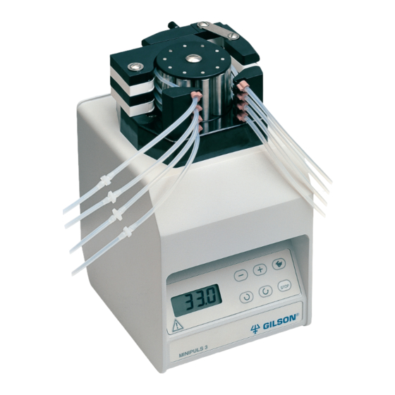
ENGLISH 2 - DESCRIPTION Gilson’s MiNiPULs 3 is a peristaltic pump, designed for transferring fluids with a high level of speed stability and a low pulsation level. it has many applications, including the following: transferring solutions, emulsions, suspensions, and gases at up to 200 °C. -
Page 6: Pump Head
Pump Head R1 Pump Head Pump heads are composed of a rotor with idle stainless steel rollers that press a flexible piece of tubing against a cam. in this way liquids are pumped by a peristaltic effect. R2 Pump Head There are two types of pump heads: the MP (standard) and the HF (High Flow) series. -
Page 7: Back Panel
ENGLISH Back Panel The back panel holds: a power cord socket and a power switch (with fuses) a fan an input/output control socket a 9-pin GsiOC socket. Membrane Keypad Assembly The membrane keypad assembly is integrated with the main housing. - Page 8 Push the barrier strip connector into the socket on the MiNiPULs 3. The connector is designed to fit snugly into the socket. Connect the other ends of the wires to the corresponding output terminals on the controlling device.
-
Page 9: Changing The Pump Head
Make sure that the connectors are inserted correctly by referring to the diagram, which indicates the function of each pair, on the rear panel of the MiNiPULs 3. details of how to connect a MiNiPULs 3 to specific Gilson instruments are given in Chapter 5. -
Page 10: Tubing - Selection And Fitting
HF models can use either type of tubing. The user then links the MiNiPULs 3 with other hydraulic com- ponents of the system (for example chromatographic columns) using connection tubing, connectors, and couplers of appropriate diameter and material. - Page 11 ENGLISH Diameter and Flow Rate select the peristaltic tubing diameter that gives the desired flow rate by reference to the speed/Flow rate Charts (page 13 to page 15). These graphs represent the values obtained in laboratory tests, where the liquid was allowed to flow freely from the tubing against atmospheric pressure only. There was no additional back-pressure (e.g.
- Page 12 Fitting the Tubing Adjustment screw locking key MP pump heads trigger key Only peristaltic tubing with retaining stops can be fitted to MP pump heads. 1) Unlock each channel of the head by pressing the trigger key (A) towards the roller barrel. 2) Position the tubing around the rollers;...
- Page 13 ENGLISH Flow Rate Selection & Adjustment Selection The following charts may be used to select the approximate pump head speed (rpm) that is required to achieve the desired flow rate. if it is possible to choose between tubings of different sizes (refer to the Appendix), select a middle range tubing that gives a middle range speed.
- Page 14 MP Model - Medium Sized Tubing Pump Head Speed (RPM) Speed/Flow rate Chart (Medium Sized Tubing) HF Model - Large Sized Tubing Pump Head Speed (RPM) Speed/Flow rate Chart (Large Sized Tubing) - 14 -...
- Page 15 ENGLISH HF Model - Fluoroelastomer Tubing Pump Head Speed (RPM) Speed/Flow rate Chart (Fluoroelastomer Sized Tubing) HF Model - Silicone Tubing Pump Head Speed (RPM) Speed/Flow rate Chart (Silicone Sized Tubing) - 15 -...
-
Page 16: Recommendations
- F1179931, small bore (1 to 2 mm) to large bore (2 to 3 mm), - F1179951, large bore (2 to 3 mm) to large bore. Metal sleeve connectors are used for very small bore tubing. Three sizes are available from Gilson for connecting tubing from 0.25 mm id to 0.8 mm id. - Page 17 Gilson chromatography column outlets. Couplers Two types of coupler are available. Reference F1410050 consists of a set of five PVdF couplers for linking two standard Gilson connection screws (1/4”-28 TPi). Reference 495036 consists of one Teflon coupler for linking ...
-
Page 18: Operation
4 - OPERATION install the pump and make the required hydraulic and electrical connections, as described in Chapter 3. switch the pump on using the rear-panel switch. Then refer to the following sections, which describe how to use the keypad to control the pump, or to Chapter 5 if the pump is to be remotely controlled. -
Page 19: Autostart Function
ENGLISH When pressed, the display shows ( - - -) or ( - - -), but the previous speed is stored in memory. if pressed a second time, the pump rotates at the preset speed; the same is applicable if either or the key is pressed. -
Page 20: Maintenance And Troubleshooting
5) Press the STOP key to validate the selection. Changing the Identification Number The MiNiPULs 3 identification (id) number is factory set at 30. it could be necessary to change this id number if several pumps communicate on the same GsiOC bus. -
Page 21: Remote Control
ENGLISH 5 - REMOTE CONTROL remote contact control is only available after the stop key of the MiNiPULs 3 is pressed. remote contact control is not available if the MiNiPULs 3 is already under GsiOC control. Electrical Contact Control 0-5 V, giving 0 - 100%... -
Page 22: Control By Gilson Devices
The CPU must have at least 512 KB of rAM. The PC must have a keyboard, a video monitor with its controller card, 9 cm (3.5 inch) floppy disk drive with its controller, an rs232C card, and a Gilson 605 rs232 Adapter or 506B/C system interface. - Page 23 The MiNiPULs 3 offers two levels of digital control mode: Keypad and Remote. The Keypad mode is the default. The MiNiPULs 3 normally works through the keypad and responds to immediate commands through GsiOC. it is similar to the local mode of some computer-controlled devices.
- Page 24 Command % Command K type Intermediate type Immediate Mode Keypad and remote Mode Keypad and remote Function request keypad status Function Module identification response format “312vx.y” where response format “cs” where vx.y identifies the software version “c” is the code of the last key pressed. “<”...
- Page 25 ENGLISH Examples Example 1: Command Comment To set the speed at 25 rpm. (I) $ ; Master reset (B) Sr ; Set remote mode This sets the speed without starting the pump; it (B) r2500 ; Set speed to 25.00 rpm does not rotate.
-
Page 26: Appendices
6 - APPENDICES This chapter contains part numbers and technical data (specifications). Part Numbers and Accessories six pump-heads are available: four standard models (1, 2, 4, or 8 channels) and two HF models (2 or 4 channels). The speed control module, which may be set to operate at either 220-240 V or 100-120 V (refer to Chapter 3), is supplied with an accessory package containing... -
Page 27: Additional Accessories
ENGLISH Additional Accessories Additional accessories such as tubing and connectors can be supplied by Gilson. These items are described in Chapter 3 and listed below. Connectors Metal Sleeve Connectors for Small Bore Reference Description Tubing F117985 Set of 5 Stainless steel connectors 0.6 mm od F117986 Set of 5 Stainless steel connectors 0.8 mm od... - Page 28 Polyvinylchloride (PVC) Connection Reference Description Tubing F117952 3 meters tubing 0.25 mm id F117953 3 meters tubing 0.38 mm id F117954 3 meters tubing 0.51 mm id F117956 3 meters tubing 0.76 mm id F117958 3 meters tubing 1.02 mm id F117960 3 meters tubing 1.30 mm id F117962...
- Page 29 ENGLISH Silicone Tubing Reference Description Silicone Calibrated Peristaltic tubing F1825111 Set of 4 Silicone flow tubes 0.6 mm id 0.40 meter lengths of silicone peristaltic F1825112 Set of 4 Silicone flow tubes 1.0 mm id tubing (with stops). F1825113 Set of 4 Silicone flow tubes 2.0 mm id F1825114 Set of 4 Silicone flow tubes 2.8 mm id Silicone Connection Tubing Reference Description...
-
Page 30: Technical Data
Technical Data Operating Temperature: 4 - 40°C. No warm-up time is required before operation. Position: Upright only (vertical ± 5°). Head Speed: 0.01 to 48 rpm. Torque: Greater than 3 Nm at any speed below 25 rpm, at or above the nominal voltage (110V or 220V). Motor Speed Stability: 0.5% for any variation of line voltage, torque, or temperature. - Page 31 ENGLISH - 31 -...
- Page 32 LT801121/0 - ©2011 Gilson SAS All rights reserved May 2011 English Printed in France Specifications subject to change without notifications - errors omitted. www.gilson.com sales@gilson.com service@gilson.com training@gilson.com Gilson, Inc. World Headquarters 3000 Parmenter Street P.O. Box 620027 Middleton, WI 53562-0027, USA...
Need help?
Do you have a question about the Minipuls 3 and is the answer not in the manual?
Questions and answers