Advertisement
Table of Contents
- 1 Specifications
- 2 Safety Marks
- 3 Specification Compliance
- 4 Product Features
- 5 Quick Start
- 6 Front Panel Description
- 7 Output Checking
- 8 Major Specification
- 9 Operation
- 10 Keypad Description
- 11 Front Panel
- 12 Voltage Setting
- 13 Current Setting
- 14 Output Switch
- 15 Voltage Calibration
- 16 Current Calibration
- Download this manual
Advertisement
Table of Contents

Related Manuals for TekPower TP3016M Series


Summary of Contents for TekPower TP3016M Series
- Page 1 User Guide TP3016M Series Switching Mode DC Power Supply...
-
Page 2: Specifications
Introduction I. Quick Start 1.1 Front Panel Description 1.2 Pre-Checking 1.3 Quick Start 1.4 Output Checking II. Specifications 2.1 Major Specification 2.2 Supplementary Characteristic III. Operation 3.1 Keypad 3.2 Front Panel 3.3 Voltage Setting 3.4 Current Setting 3.5 Output Switch 3.6 Data Saving Operation... - Page 3 3.7 Recall Saving Operation 3.8 USB Power Charging IV. Calibration 4.1Voltage Calibration 4.2 Current Calibration...
-
Page 4: Safety Marks
Introduction Thank you for selecting the TP3016M Switching DC Power Supply, please read this user guide before the operation. Safety This manual contains important safety and operation instructions for correct use of power supply. Read through the manual and pay attention to the markings and labels of this unit to be connected. Do not install the substituted spare parts or operate the modification without permission, please send the unit back for A/S to our authorized dealers or factory for guaranty of the stability of the unit. -
Page 5: Specification Compliance
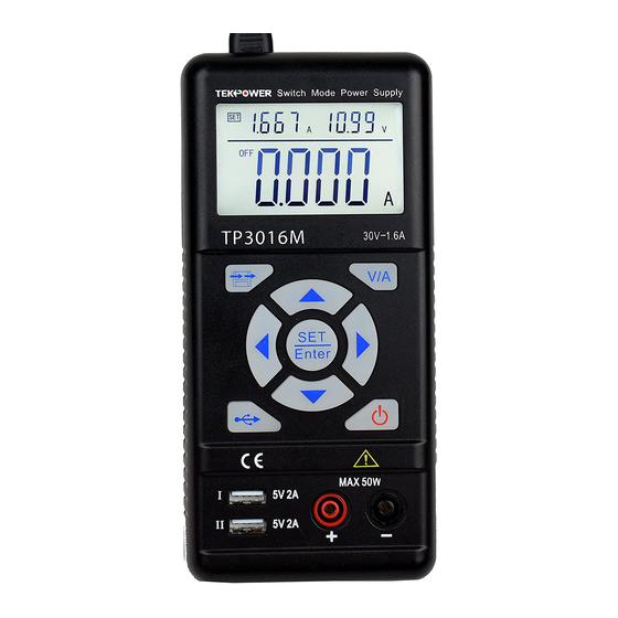
Failure to observe this warning may cause injury to persons and damage to power supply or connected equipment. CAUTION: Failure to observe this warning may result in damage to equipment and improper functioning of power supply. Grounding High Voltage Attention on the Warning or Caution Specification Compliance TP3016M Switch mode DC Power Supply is compliance with the specification described in this manual. - Page 6 TP3016M is the single output switch mode DC power supply with max. 30V output voltage, 1.6A output current and max. output power as 50W. TP3016M is integrating the AC/DC and DC/DC 2nd level voltage regulator technology, the AC/DC input is adapting the worldwide voltage range. The DC/DC is using the synchronous buck mode, which with the high efficiency and high speed dynamic response performance.
-
Page 7: Quick Start
I. Quick Start This chapter describes the basic check points on TP3016M for making sure the proper operation, as well as the functions of TP3016M. Front Panel Description 1 – Current Setting Indicator 2 – Voltage Setting Indicator 3 – Measured Value Display 4 –... - Page 9 1.2 Pre-Checking Before the operation, please check the accessories are fully included, if any missing, please contact the local distributor. Power Cord – 1PC (Compliance with the standard voltage of the region) □ User Guide – 1PC □ Connect with power and switch on TP3016M, the unit start the self-system checking, the LCD displays 0.5s, date of manufacturing, production lot, model number version number in turn.
- Page 10 UP Arrow Key + DOWN Arrow Key Press UP arrow key to activate the LCD backlit Press DOWN arrow key to exit the LCD backlit LEFT Arrow Key + RIGHT Arrow Key Press LEFT arrow key to decrease the contrast of LCD Press RIGHT arrow key to increase the contrast of LCD V/A Key Press the V/A key to activate voltage measurement and read the voltage value from display.
-
Page 11: Output Checking
power charging mode; then, push and light the OUT button, the TP3016M is working as power charger. Push the USB button again and USB button lights out to exit USB power charging mode. SET Button + V/A Button + Direction Arrow Keys Push the SET button, by pressing the direction arrow keys to adjust the voltage value setting, Push the V/A button to switch the current value setting mode, by pressing the direction arrow keys to measured current value. - Page 12 2) Push and light the OUT button, the indicator of CV is light on at LCD display. 3) Setting the voltage of power supply Push the V/A button and shift to voltage display mode, adjust various voltage values then, check the voltage value displayed at LCD is approaching the settled voltage value and within the tolerance, current value is showed as 0A.
-
Page 13: Major Specification
1) Switch on the product, the power is off and the indicators of CC & CV are light off. 2) Adjust voltage value is over 5V and current value is over 1A. 3) Push and light the OUT button. 4) Connect the output terminals by wire for short circuit, the light of OUT button is off and output off. - Page 14 Input Voltage 110AC~ 60Hz Input Current Voltage range 0.5V~30V Output Rating Current range 0~3.75A Voltage CV≦0.01%+3mV Line Regulation ±%of output + offset Current CC≦0.01%+3mA Voltage CV≦0.02%+3mV Load Regulation ±%of output + offset Current CC≦0.02%+3mA Voltage 10mV Measurement Accuracy Current ≦0.05%+5mV Measured Value Accuracy Voltage @ 25℃...
-
Page 15: Operation
2.2 Supplementary Characteristic Build-in EEPROM Recommended Calibration Time:1 Time/Year AC Input Power: 110VAC, 60 Hz Operating Temperature: 0 to 40 ℃ Storage Temperature: -20 to 70 ℃ III. Operation Check the rating label of the power supply and ensure that it complies with the AC mains voltage that is to be used. -
Page 16: Front Panel
SET/ENTER Voltage & Current Setting/Enter STORE/RECALL Data Saving/Recall DOWN LEFT RIGHT Direction Arrow Keys 3.2 Front Panel After power on, the panel operation mode is the default setting of power supply and all the functional buttons can be operated. 3.3 Voltage Setting The voltage setting range is from 0.50V to 30V;... -
Page 17: Current Setting
Remark: It is possible to set voltage values once the outputs are valid. However, for protection of the load, it is recommended to stop output before voltage setting. Due to the total power limit, current settings might be decreased automatically once voltage setting increasing. -
Page 18: Output Switch
ENTER 0. 000 A ---------> 2.000 A ------------ > OK Remark: It is possible to set current values once the outputs are valid. However, for protection of the load, it is recommended to stop output before current setting. 3.5 Output Switch Under the panel operating mode, by pushing OUT button to shift output status. - Page 19 STORE ENTER -----> OK 3.7 Recall Saving Operation Under the panel operating mode, push the RECALL button for getting the saved data from memory; follow the setting steps as below: 1. Switch on the power supply 2. Push RECALL button to enter data recall mode, the min. value position is flickering and displayed RECALL icon in LCD.
- Page 20 3.8 USB Power Charging Push the USB button and light the green indicator, the default setting is voltage @ 5.1V and current @ 2.0A, the LCD will display 5.1V, current value also can be as 0A. Connect the mobile phone via USB cable for power charging.
- Page 21 IV Calibration Follow the below chart, connect the 5 digit displayed volt meter, current meter, resistance (10Ω/100W) into the output terminals, calibration follow the steps start from point of zero voltage - voltage coefficient – current zero – current coefficient. Hold the SET button to switch on power supply till “REF”...
-
Page 22: Voltage Calibration
4.1 Voltage Calibration At the power supply displayed 2.000A & 05.00V in setting area of LCD and **.**V displayed in main part of LCD. Connect the output terminal with an external reference voltage meter and shift to CV mode. Hold the LEFT or RIGHT arrow keys to move the cursors to left or right and push the UP or DOWN arrow keys to adjust the values same as readings of external reference voltage meter, then click ENTER button to finish the voltage bias calibration. - Page 23 At the power supply displayed 3.000A & 20.00V in the setting area of LCD, hold the LEFT or RIGHT arrow keys to move the cursors to left or right and push the UP or DOWN arrow keys to adjust the values same as readings of external reference voltage meter, then click ENTER button to finish the current gain calibration.
Need help?
Do you have a question about the TP3016M Series and is the answer not in the manual?
Questions and answers