
Related Manuals for Monicon Instruments GTR-168

Summary of Contents for Monicon Instruments GTR-168
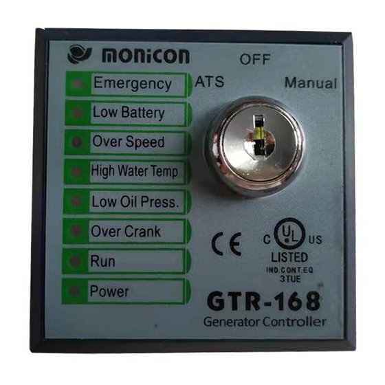
- Page 1 GTR-168 Generator Controller Manual Site:http://www.monicon.com.tw :s a l e s @ m o n i c o n . c o m . t w E - m a i l...
- Page 2 3 kinds of operation mode: Manual, Auto, Off. No special training is required due to the easy operation. Fault protection includes: Emergency stop, Over speed, High water temperature, Low oil pressure, and Over crank. GTR-168 also displays the low battery voltage warring, and indicates the running status and power status.GTR-168 equips with high firm continental-type terminal that provides easy plug in and removal.
- Page 3 Monicon Tech. GTR-168 3. Back Panel Function Description Fig. 2 GTR-168 Controller Back Panel Number Description Code Input power (Battery +) Ground (Battery -) Output starter relay Motor Output fuel valve relay Valve Output alarm relay Alarm Output stop relay...
- Page 4 Pin9 Cooling time 0 Sec 60 Sec 150 Sec 300 Sec List 3 Cooling Time Pin10:Idle / Pre-heat Function Select【ON:Idle;OFF:Pre-heat】 4. Case Dimension Fig. 3 GTR-168 Case Dimension of Back View Fig. 3 GTR-168 Case Dimension of Back View Ver.:V168007...
- Page 5 Monicon Tech. GTR-168 5. Specifications DC supply: 8~36 VDC Power Consumption: Max.5 W Measuring Frequency: 0~75 Hz (min AC Volt. 5V ; max AC Volt. 300V) Relay Output : Start output:5A Valve output:5A Idle / Pre -heat output:5A Alarm Output:5A Stop output :5A...
- Page 6 Monicon Tech. GTR-168 7. Remark (UL File E319081) “Maximum Surrounding Air Temperature 60℃” “For Use on a Flat Surface of a Type 1 Enclosure” or equivalent statement. Instructions for installation in a Pollution Degree 2 environment. Unless the proper wiring connections are plainly evident, wiring terminals shall be marked, or the device shall be provided with suitable wiring diagram to indicate the connections.
Need help?
Do you have a question about the GTR-168 and is the answer not in the manual?
Questions and answers