ASA Electronics ACM135 Installation And Operating Instructions Manual
Air conditioner & heat pump
digital control for ducted system
Hide thumbs
Also See for ACM135:
Table of Contents
Advertisement
09/23/2013
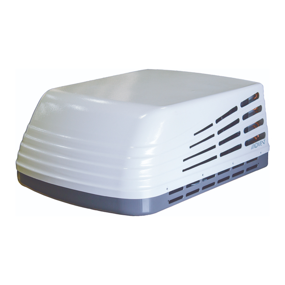
AIR CONDITIONER & HEAT PUMP
DIGITAL CONTROL FOR DUCTED SYSTEM
INSTALLATION AND OPERATING INSTRUCTIONS
FOR ACM135, ACM135SP,ACM150,ACM150SP,ACRG15,ACTH12
RECORD THIS UNIT INFORMATION FOR FUTURE REFERENCE:
Model Number:
Serial Number:
Date Purchased:
This manual must be read and understood before installation, adjustment, service, or maintenance
is performed. This unit must be installed by a qualified service technician. Modification of this
product can be extremely hazardous and could result in personal injury or property damage.
ROOM AIR
CONDITIONER
3TY1
Advertisement
Table of Contents

Related Manuals for ASA Electronics ACM135


Summary of Contents for ASA Electronics ACM135
- Page 1 AIR CONDITIONER & HEAT PUMP DIGITAL CONTROL FOR DUCTED SYSTEM INSTALLATION AND OPERATING INSTRUCTIONS FOR ACM135, ACM135SP,ACM150,ACM150SP,ACRG15,ACTH12 RECORD THIS UNIT INFORMATION FOR FUTURE REFERENCE: Model Number: Serial Number: Date Purchased: This manual must be read and understood before installation, adjustment, service, or maintenance is performed.
- Page 2 GENERAL INFORMATION A. This air conditioner / heat pump is designed for: ASA Electronics (ASA) warrants to the original retail purchaser of this Advent product that should this product or any 1. Installation on a recreational vehicle. part thereof,...
- Page 3 (in) Output (cfm) supplied) disconnected or off before beginning installatiom. 2. Route the 115VAC supply wiring previously routed into the frame of the roof opening, ACM135 20 Amp 13500 50.5 16.9 31x24.9x12.9 through the strain relief of the electrical box and into the high voltage wiring area.
- Page 4 1. For one unit installation: The air conditioner / heat pump should be mounted slightly ACTH12 THERMOSTAT INSTALLATION: forward of center (front to back) and centered from side to side. See FIG.1. FIGURE 1 ACTH12 THERMOSTAT WIRING 2. For two unit installation: Install one air conditioner / heat pump 1/3 distance and the other air conditioner / heat pump 2/3's from front of RV and centered from side to side.
- Page 5 MAIN RELAY KIT WIRING C. POST LOCATION SELECTION: 1. Check for obstructions in the area where air conditioner / heat pump will be installed. A minimum clearance of 18" is required for the rear section of the air Red with White Stripe 22 AWG conditioner / heat pump to any other roof mounted object.
- Page 6 C. OPENING PREPARATION: ALTERNATIVE FREEZE SENSOR INSTALLATION Check Upper Unit to see if freeze sensor clip is preinstalled in evaporator fins. If so, 1. If the opening exceeds 14-3/8" x 14-3/8", it will be necessary to install spacers. insert the copper sensor from the Ducted Ceiling kit into the clip as show below. 2.
- Page 7 AIR RETURN GRILL INSTALLATION (ACRG15) The Air Return Grill is designed for application in systems that utilize field fabricated (OEM supplied)air ducting. The ducting must be routed through the ceiling cavity (between the interior ceiling and roof). Ducting specifications are given in the section labeled Supply Ducting and Registers.
- Page 8 If the gasket is damaged and needs replaced, please together securely. contact ASA Electronics and purchase an authorized Advent gasket for replacement. 5.Provided with the ACRG,is a divider plate which is used to separate the warm return Using other gasket material is not recommended and could result in warranty denial.
Need help?
Do you have a question about the ACM135 and is the answer not in the manual?
Questions and answers