Table of Contents
Advertisement
Advertisement
Table of Contents

Related Manuals for AEI Security & Communications 3400


Summary of Contents for AEI Security & Communications 3400
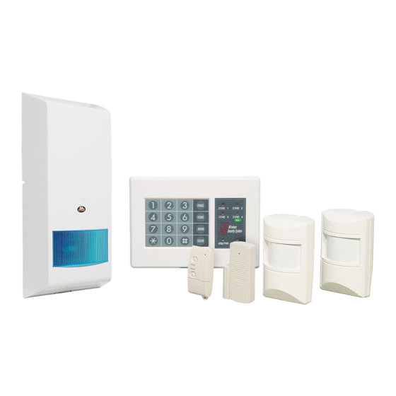
- Page 1 Wireless Alarm system Model 3400 Installation & Operation Manual...
-
Page 2: Table Of Contents
CONTENTS 1. INTRODUCTION This Wireless Security System represents a major improvement in protection for your home and property. The use of Wireless Detectors provide easy and convenient method of use and installation and enables the use of as many wireless detectors as required. 1. -
Page 3: Illustration & Description
ZONE 1 – 4 LED : ILLUSTRATION & DESCRIPTION The Zone LED’s illuminate when a detector has been activated. If activated when the system is in Disarm mode the LED will remain on for 3 minutes only, If activated in Arm mode the LED will remain on until the system is re-armed. -
Page 4: Glossary Of Terms & Abbreviations
WIRELESS PASSIVE INFRA-RED DETECTOR (PIR) 2. GLOSSARY OF TERMS & ABBREVIATIONS Fig.3 PIR DETECTOR To detect persons moving within its protected area. Passive infrared detector Printed circuit board INDICATOR The red LED operates when the PIR is set to the TEST mode Magnetic Door Transmitter Indicator lights on control... -
Page 5: Planning Your Installation
3. PLANNING YOUR INSTALLATION CONTROL PANEL Before proceeding with any part of the installation you must give very careful consideration to the The optimum transmitting range of your detectors is dependant on the location of your Control Panel location of detectors, the control panel and external siren unit. It would prove extremely useful to and the number of walls between your detectors and Control Panel. -
Page 6: Installing & Preparing The System For Use
PREPARE THE SYSTEM FOR INSTALLATION 4. INSTALLING & PREPARING THE SYSTEM FOR Setting the Site Code Having prepared the system for installation and planned the detector layout within the building you The site code is set using the first 9 DIP switches in all your Wireless detectors,together with the 9 should install the units in the following order. - Page 7 If you have a pet, place the included Pet-Immune Sticker on the lowest portion of the screen Magnetic Contacts Install a 9 volt alkaline battery and refit the cover. A magnetic contact consists of two elements, inbuilt reed sensor, and a magnet causing activation ...
-
Page 8: Remote Control
3) Remote Control Note : The use of other types of battery in the Control Panel will cause acid damage and will invalidate your Warranty. Before use, check that you have set the correct Site Code. Refer to Fig. 9. Please observe all precautions as previously stated in this manual. -
Page 9: Programming The System Memory
Press the command code *0 0 # Press new security code *_ _ _ _ # For example: you want to set up your new code as 3400 from the initial setting: *1 2 3 4 #*0 0 #*3 4 0 0 #... - Page 10 Changing the Batteries PROGRAMMING CODE FOR THE 3400 SYSTEM ONLY FACTORY SYSTEM SETTING The Control Panel back up Batteries FUNCTION DEFAULT PROCEDURE SETTING 1) *SECURITY CODE# REMARKS This Batteries fitted inside the Control Panel are commonly referred to as Ni-Mh Rechargeable. Once 2) *COMMAND...
-
Page 11: Testing
7. TESTING PERIODIC TESTING AND MAINTENANCE Testing the PIR detectors and MDT units Periodic Testing Performing periodic test functions is important in order to confirm continual operation of the system Provided you have followed the previous section accurately, all PIR detectors will have been set to the whilst at home and when away. -
Page 12: Problem Solving And Fault Finding
WIRING DIAGRAMS 9. PROBLEM SOLVING AND FAULT FINDING Identifying Tamper switch problems Failure to check the correct position of the Tamper springs when refitting covers is the most frequent cause of False Alarms and can be easily avoided during installation of the System. When clipping Tamper protected covers into place it is vitally important to check that the Tamper spring is activating the switch well before the cover is refitted. - Page 13 What to do if you forget your Keypad Security Code If you forget your Keypad Security Code you must perform the Global reset function. This restores the memory back to the factory pre-set codes. Perform the following steps: Step 1) Enter the Battery Change Command Step 2) Remove the Rechargeable Ni-Cad batteries from the Control Panel Step 3) Remove the Mains Power Adaptor unit Step 4) At this point the External Siren will sound if an SAB until is fitted...
Need help?
Do you have a question about the 3400 and is the answer not in the manual?
Questions and answers