Table of Contents
Advertisement
Advertisement
Table of Contents

Subscribe to Our Youtube Channel
Related Manuals for RFI ASM1317

Summary of Contents for RFI ASM1317
- Page 1 User’s Manual Antenna System Monitor ASM1317 ASM3852 ASM7487 ASM8796 Base Line 2.83 Document Number: INS40821-3 Australian Standard Patent No. 2011218778 Australian Patent Application No. 2016250327 U.S. Patent No. 8,983,415 U.S. Patent Application No. 15/343,133...
- Page 2 50 countries. One of RFI’s key principals is to remain totally customer focused as we recognise our future depends on the success of our customers. We know that to be chosen as your supplier we must add value to your business and to achieve this we will work hard to deliver the best product when and where you need it and back this up with the very best technical support available.
-
Page 3: Document Number Ins40821
_____________________________________________________________________________ Disclaimer Product part numbering in photographs and drawings is accurate at the time of printing. Part number labels on RFI products supersede part numbers given within this manual. Information is subject to change without notice. Asia Pacific | EMEA | Americas... -
Page 4: Table Of Contents
ASMxxxx Series User’s Manual TABLE OF CONTENTS 1. GENERAL DESCRIPTION ....................10 2. APPLICATION DIAGRAM ....................12 3. ASM - ELECTRICAL AND MECHANICAL SPECIFICATIONS ........... 13 4. COUPLER - ELECTRICAL AND MECHANICAL SPECIFICATIONS ......... 14 5. CAM/SAM/RSM - ELECTRICAL AND MECHANICAL SPECIFICATIONS ......14 6. - Page 5 ASMxxxx Series User’s Manual 10.42 Configuration – History ....................109 10.43 Configuration – Communications ................111 10.44 Calibration Menu ......................114 10.45 Calibration – System Isolation Tests ................115 10.46 Calibration – Rx Port ....................117 10.47 Calibration – Tx Port 1 ....................120 10.48 VSWR Calibration ......................
- Page 6 2011, RF Industries Pty Ltd. All rights reserved. Reproduction, adaptation or translation without prior written permission is prohibited except as allowed under copyright laws. For further information or help with this product contact your nearest RFI sales office or through the following; Region...
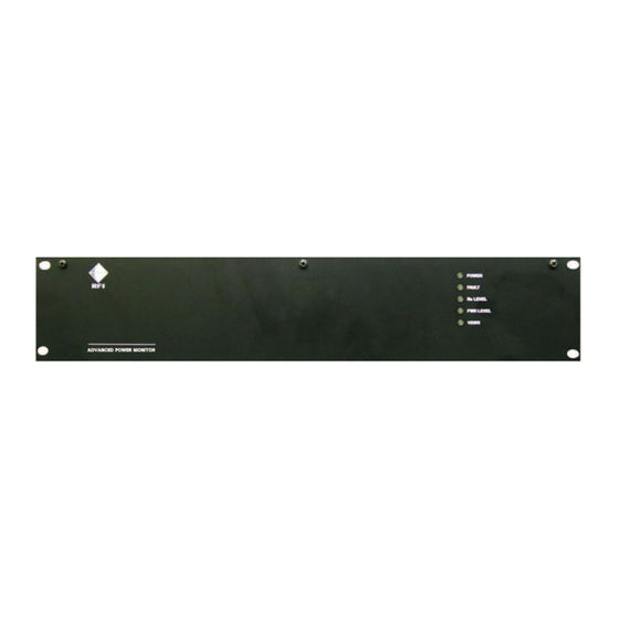
- Page 7 ASMxxxx Series User’s Manual Antenna System Monitors ASMxxxx Series Front View ASMxxxxK1 Series Rear View ASMxxxxK2 Series Rear View Asia Pacific | EMEA | Americas...
- Page 8 ASMxxxx Series User’s Manual Antenna Line Couplers SP1318-2440-DFF1RU (132-174MHz) Front View Top View SP3855-4440-DFF1RU (380-520MHz) Front View Top View SP7496-4440-DFF1RU (746-960MHz) Front View Top View Asia Pacific | EMEA | Americas...
-
Page 9: Optional Modules
ASMxxxx Series User’s Manual Optional Modules CAM0000 Series Channel Alarm Module (CAM) Front Panel Layout Channel Alarm Module (CAM) Rear Panel Layout SAM0000 Series Site Alarm Module (SAM) Front Panel Layout Site Alarm Module (SAM) Rear Panel Layout RSM0000 Series Receive Systems Module (RSM) Rear Panel Layout Asia Pacific | EMEA | Americas... -
Page 10: General Description
- with additional ALCs available separately for applications requiring more than one combiner/antenna system to be monitored. RFI can also supply PIM-rated 7/16 DIN right-angle adapters if required to assist in rack cabinet layout and installation of the coupler(s) if required. - Page 11 ASMxxxx Series User’s Manual Channel Alarm Modules (CAMs) and Site Alarm Modules (SAMs) If desired, optional Channel Alarm Modules (CAMs) or Site Alarm Modules (SAMs) may be added to the ASM at any time. CAMs/SAMs are connected using a daisy chained cabling approach using two cables - “DC power” and “Comms”. The CAM is no longer manufactured and the SAM is a direct (and enhanced) replacement.
-
Page 12: Application Diagram
ASMxxxx Series User’s Manual 2. Application Diagram Tx ANTENNA 1 TO ADDITIONAL COUPLERS IF REQUIRED Rx ANTENNA(s) ASM + 1 ANTENNA LINE COUPLER COUPLER TOP VIEW - MOUNTED ON 1RU FRONT PANEL Tx COMBINER (1) 4 ASSIGNED ALARM RELAY OUTPUTS ASM REAR VIEW MONITORED CHANNELS... -
Page 13: Asm - Electrical And Mechanical Specifications
ASMxxxx Series User’s Manual 3. ASM - Electrical and Mechanical Specifications ASM Model Number ASMxxxx Series Frequency range ASM1317 132-174MHz (Tx power and Rx level monitoring) ASM3852 380-520MHz ASM7487 746-870MHz ASM8796 870-960MHz Maximum number of monitored channels Tx = 80... -
Page 14: Coupler - Electrical And Mechanical Specifications
ASMxxxx Series User’s Manual 4. Coupler - Electrical and Mechanical Specifications Coupler Model Number SPxxxx-2440-DFF1RU / SPxxxx-4440-DFF1RU Frequency range SP1318-2440-DFF1RU 130-180MHz SP3855-4440-DFF1RU 380-550MHz SP7496-4440-DFF1RU 746-960MHz Insertion Loss < 0.2dB Input and Output Port Return Loss > 20dB Coupling Loss 40dB (+/- 0.7) Maximum input power 750W Maximum PIP... - Page 15 50VDC @ 1A Alarm Inputs 10 (configurable) digital (general purpose/one per alarm output) 4 (configurable) temperature/analogue/digital (general purpose) Alarm Input Logic temperature RFI temperature sensor analogue -60V DC to +60V DC analogue -60V DC to +5V DC digital “0” = <2.5V DC “1”...
-
Page 16: Ordering Information
Ordering Information Model Number Description Antenna System Monitor 132-174MHz ASM1317 80 Ch / 4 Tx Fwd / 4 Tx Rfl / 1 Rx Port / 9-36VDC Antenna System Monitor 132-174MHz ASM1317-48 80 Ch / 4 Tx Fwd / 4 Tx Rfl / 1 Rx Port / 36-60VDC... - Page 17 ASMxxxx Series User’s Manual Ordering Information Channel Alarm Module Description Channel Alarm Module 9-36V DC (Obsolete – use SAM0000) CAM0000 Channel Alarm Module 36-60V DC (Obsolete – use SAM0000-48) CAM0000-48 Site Alarm Module Description SAM0000 Site Alarm Module 9-36V DC SAM0000-48 Site Alarm Module 36-60V DC SAM0000-TS...
-
Page 18: Unpacking
ASMxxxx Series User’s Manual 7. Unpacking The ASM is packed into a custom designed cardboard insert, box container and sleeve together with a single Coupler and AC to DC power pack if the AC option has been ordered. Optional CAM, SAM, and RSM modules are similarly packaged. Packed with the ASM and Coupler will be the Factory Test Sheet (FTS) and Quick Start Guide (QSG). -
Page 19: Firmware License Agreement
Firmware is on a “fit-for-purpose, best effort” approach. RFI will not be liable to the user for claims and liabilities of any kind arising out of or in any way related to the use of the Firmware by the user or any third party. -
Page 20: Installation
ASMxxxx Series User’s Manual 9. Installation WARNING: Power should not be applied to electrical equipment during Installation, and cabling connection/disconnection activities. Apply power only when all installation and cabling activities have been completed. The ASM, (optional) CAM/SAMs, and Coupler(s) are designed to be mounted into a standard EIA 19” rack frame using industry standard 19”... -
Page 21: Operation
In addition to using the integral Web Browser GUI, the ASM (and any connected CAM/SAM/RSMs) can also be communicated with via a CLI (Command Line Interface) using plain text format via a Telnet IP session. For information on the CLI format please contact the RFI Technical Support team. Asia Pacific | EMEA | Americas... -
Page 22: Ethernet Connection, Set-Up, And Reset
ASMxxxx Series User’s Manual 10.1 Ethernet Connection, Set-up, and Reset Web Browser GUI (Graphical User Interface) The ASM utilizes an on board web server to provide web browser access to the GUI. This can be accessed connecting to the ASM via a short Ethernet cable jumper from a laptop/notebook directly to the ASM or remotely via a TCP/IP network. A standard Ethernet CAT5e jumper cable terminated with RJ45 connectors at either end is provided for convenience in the packing box with the ASM. - Page 23 ASMxxxx Series User’s Manual This is done for example in Windows 7™ in the following manner; 1. Select “Start” from status menu 2. Single click – “Control Panel” 3. Single click – “ Network and Sharing Center” 4. Single click - “Change Adapter Settings” on the left hand side menu 5.
-
Page 24: Log In Page
ASMxxxx Series User’s Manual 10.2 Log In Page The default User Name is “master” and Password is “master”. This default user name and password provides complete and unrestricted access to the ASM (Level 3). Once logged in, this can be changed via the User Management screen under the Maintenance menu tab. User Name and Password Levels Level 1: User name and password access via the web browser GUI interface displays only status screens. -
Page 25: System Overview
ASMxxxx Series User’s Manual 10.3 System Overview This page displays an overview of the current unit status. The overall summary alarm status is displayed, for each Port and for the System, with each line representing the current alarm status on its respective Status page in the GUI menu. Clicking on any Group item will navigate you to that item’s Status page so that the detail of the alarms can be viewed. -
Page 26: Status Menu
ASMxxxx Series User’s Manual 10.4 Status Menu The “Status” menu allows all of the ASMs measurement parameters to be viewed. Selecting each indented topic under “Status” will display that item as a separate display page. The “Receive Systems Module” and “Alarm Modules” menu items appear only if one or more (optional) Channel Alarm Note: Module (CAM), Site Alarm Module (SAM) or Receive Systems Module (RSM) is installed. -
Page 27: Status - System Isolation Tests
ASMxxxx Series User’s Manual 10.5 Status – System Isolation Tests The “Status – Isolation Tests” page reports the current status of the System Isolation Tests settings. Settings: Automatic System Isolation Tests: Indicates if the Automatic System Isolation Tests function is currently enabled/disabled in the ASM. If ‘enabled’, the System Isolation Tests are performed automatically, based on the Automatic Test Schedule. - Page 28 ASMxxxx Series User’s Manual Next Scheduled Test: The next scheduled date/time that the Automatic Test Schedule will be performed. Parameters Used: The known RF site parameters that are used in performing the System Isolation Tests. These parameters are collated from data fields on the various ASM GUI configuration screens, Test Results: The displayed results of the System Isolation Tests.
- Page 29 ASMxxxx Series User’s Manual Test Now: The “Test Now” button can be selected at any time to manually initiate a System Isolation Tests measurement. All of the measurement fields may take time to populate subject to when the Tx frequencies configured in the test next transmit. The ‘Test Now”...
-
Page 30: Status - Receive Systems Module
ASMxxxx Series User’s Manual 10.6 Status – Receive Systems Module The “Receive Systems Module” menu item appears only if an (optional) Receive Systems Module (RSM) is installed. Note: The Receive Systems Module “Status” page reports the current status of the RSM Settings: Model: Displays the type of Receive Systems Module. - Page 31 ASMxxxx Series User’s Manual Hardware Revision: Displays the Receive Systems Module’s Hardware Revision. Module Serial Number: Displays the Receive Systems Module’s Module Serial Number. RxA to Rx-Output Gain: Displays the configured gain in the signal path from the RxA Input to the Rx Output to the ASM. RxB to Rx-Output Gain: Displays the configured gain in the signal path from the RxB Input to the Rx Output to the ASM.
- Page 32 ASMxxxx Series User’s Manual Reset Peak Levels: Click this button to reset the stored Peak Level value Refresh: Click this button to manually trigger a page refresh. Note: The background behind a measurement value is highlighted in colour to indicate its current status. Green denotes ‘no alarm’, Yellow denotes ‘warning’, and Red denotes ‘alarm’.
-
Page 33: Status - Rx Channels 1-20
ASMxxxx Series User’s Manual 10.7 Status - Rx Channels 1-20 The “Status - Rx Channels” pages report the current status of Rx channels. To prevent display clutter, Rx channels are displayed with up to 20 channels shown per page. Chan No: Indicates the configured sequential channel number. - Page 34 ASMxxxx Series User’s Manual Act: An “active” indicator that shows the status of the Last recorded power above threshold value being display. The three states that may appear are; The indicator symbol is displayed but is dull – the value shown was not measured in the last measurement cycle. The indicator symbol is displayed and is lit –...
-
Page 35: Status - Tx Port 1
ASMxxxx Series User’s Manual 10.8 Status – Tx Port 1 The Tx Port “Status” page reports the current status of all Tx channels allocated to the selected Tx Port. Note: The Status - Tx Port screens have been optimised for accuracy. The Channel Diagnostics page has been optimised for fast screen refresh rate to assist tuning and other maintenance activities. - Page 36 ASMxxxx Series User’s Manual The configured channel scanning On/Off status. If this is “OFF”, the measurements for this channel will not be performed. This field may be used if channels have been disabled or temporarily removed from the site. Freq: The configured frequency of the channel.
-
Page 37: Status - System
ASMxxxx Series User’s Manual 10.9 Status – System This System Status” page reports the current system settings and alarm summary. The “Receive Systems Module” and “Alarm Modules” menu items appear only if one or more (optional) Channel Alarm Note: Module (CAM), Site Alarm Module (SAM) or Receive Systems Module (RSM) is installed. Up to ten (10) CAM/SAM units and one (1) RSM may be fitted to each ASM as required. - Page 38 ASMxxxx Series User’s Manual Model: The model designator of this unit. Unit ID: This field reports the unique ID number that has been assigned by the Remote Manager application (If being used). If the unit is not managed through the Manager application, this will normally be 0. Firmware version: The version of the firmware.
- Page 39 ASMxxxx Series User’s Manual VCO: If any of the unit's VCOs is experiencing lock failures, this alarm will activate. SD-Card: A regular write/read test is performed on the SD-Card. If this test fails to complete successfully, this alarm will activate. Internal Supply Rails: If any of the unit's internal supply rail voltages goes out of limits, this alarm will activate.
-
Page 40: Status - Alarm Modules - Menu
ASMxxxx Series User’s Manual 10.10 Status – Alarm Modules - Menu The “Receive Systems Module” and “Alarm Modules” menu items appear only if one or more (optional) Channel Alarm Note: Module (CAM), Site Alarm Module (SAM) or Receive Systems Module (RSM) is installed. Up to ten (10) CAM/SAM units and one (1) RSM may be fitted to each ASM as required. -
Page 41: Status - Alarm Modules - Sam
ASMxxxx Series User’s Manual 10.11 Status – Alarm Modules - SAM This page reports the status of the selected Site Alarm Module (SAM) if fitted. Asia Pacific | EMEA | Americas... - Page 42 ASMxxxx Series User’s Manual Model: Displays the type of Alarm Module. Serial Number: Displays the Alarm Module’s Serial Number. Firmware Version: Displays the Alarm Module’s Firmware Version. Hardware Revision: Displays the Alarm Module’s Hardware Revision. External Alarm Input: Displays the four (4) configurable external temperature/analogue/digital inputs. Input ID: The name assigned for the respective External Input.
- Page 43 ASMxxxx Series User’s Manual Alarm Output: Displays the ten (10) configurable relay outputs. Port: Displays the Tx Port that the Alarm Output is currently associated to. Channel: Displays the Tx Channel that the Alarm Output is currently associated to. Status: Indicates the current status of the ten (10) Alarm Outputs.
-
Page 44: Status - Alarm Modules - Cam
ASMxxxx Series User’s Manual 10.12 Status – Alarm Modules - CAM This page reports the status of the selected Channel Alarm Module (CAM) if fitted. Asia Pacific | EMEA | Americas... - Page 45 ASMxxxx Series User’s Manual Model: Displays the type of Alarm Module. Serial Number: Displays the Alarm Module’s Serial Number. Firmware Version: Displays the Alarm Module’s Firmware Version. Hardware Revision: Displays the Alarm Module’s Hardware Revision. External Alarm Input: Displays the four (4) configurable external digital inputs. Input ID: The name assigned for the respective External Input.
- Page 46 ASMxxxx Series User’s Manual Alarm Output: Displays the ten (10) configurable relay outputs. Port: Displays the Tx Port that the Alarm Output is currently associated to. Channel: Displays the Tx Channel that the Alarm Output is currently associated to. Status: Indicates the current status of the ten (10) Alarm Outputs.
-
Page 47: Status - Communications
ASMxxxx Series User’s Manual 10.13 Status – Communications This page reports the current Communications settings. Ethernet MAC Address: The physical MAC address of the unit. DHCP: If the stored value is enabled, the unit will attempt to get its IP Address, Subnet Mask and Gateway settings from a DHCP server. If a DHCP server cannot be found, the stored settings will be used and the Currently In Use status will show as disabled. - Page 48 The port number used by the SNMP Manager. Both a Primary and Secondary address may be used if required for redundant SNMP server configurations. Note: SNMP MIB files for the ASM are available from RFI. Asia Pacific | EMEA | Americas...
-
Page 49: History Menu
ASMxxxx Series User’s Manual 10.14 History Menu The “History” menu allows the ASMs logged data to be viewed. Selecting each indented topic under “History” will display that item as a separate display page. The “Receive Systems Module” and “Alarm Modules” menu items appear only if one or more (optional) Channel Alarm Note: Module (CAM), Site Alarm Module (SAM) or Receive Systems Module (RSM) is installed. -
Page 50: History - Isolation Tests
ASMxxxx Series User’s Manual 10.15 History – Isolation Tests Example of Antenna Isolation Chart This page displays the logged Isolation Tests values. Select Test: Select the Isolation Tests which you desire to display. Available selections are Antenna Isolation, Rx Gain and Tx Rejection. Select Period / Select Date: Select the past period (working back from the Select Date) for which logged data will be displayed. - Page 51 ASMxxxx Series User’s Manual When a Receive Systems Module (RSM) is fitted to the ASM, the measured values for the three receive signal paths (RxA, RxB and RE) are visible in the Isolation Tests History Chart – Antenna Isolation page. Asia Pacific | EMEA | Americas...
- Page 52 ASMxxxx Series User’s Manual Example of Rx Gain Chart This page displays the logged Rx Gain values. Select Test: Select the Isolation Tests which you desire to display. Available selections are Antenna Isolation, Rx Gain and Tx Rejection. Select Channels: Select the test frequencies that you wish to display.
- Page 53 ASMxxxx Series User’s Manual NOTE: There are documented issues with Internet Explorer™ Version 10. This may impact the presentation of some GUI features. The use of an alternate web browser is recommended. When a Receive Systems Module (RSM) is fitted to the ASM, the measured values for the three receive signal paths (RxA, RxB and RE) may be selected in the Isolation Tests History Chart –...
- Page 54 ASMxxxx Series User’s Manual Example of Tx Rejection Chart This page displays the logged Tx Rejection values. Select Test: Select the Isolation Tests which you desire to display. Available selections are Antenna Isolation, Rx Gain and Tx Rejection. Select Channels: Select the test frequencies that you wish to display.
- Page 55 ASMxxxx Series User’s Manual Note: The red lines on the displayed graph represent the alarm max/min values currently configured for this test Note: The displayed lines may commence in from the left hand side of the graph. This indicates when the associated transmitter first keyed in the selected Period.
-
Page 56: History - Isolation Tests File
ASMxxxx Series User’s Manual 10.16 History – Isolation Tests File This page allows logged test data to be downloaded, saved or displayed. Data is provided in a CSV file format for ease of import and manipulation. Select Period / Select Date: Select the past period (working back from the Select Date) for which logged data will be displayed. -
Page 57: History - Rx Power Chart
ASMxxxx Series User’s Manual 10.17 History – Rx Power Chart This page displays the logged Rx Power values for all channels. Select Rx Group: Select the Port which you desire to display. Select Period / Select Date: Select the past period (working back from the Select Date) for which logged data will be displayed. When the Select Date field is selected, a calendar will appear allowing a past date to be nominated as the starting day for the Period to apply up until. - Page 58 ASMxxxx Series User’s Manual Select Data Mode: Select the data set that you wish to display for the selected Rx Group’s channels. Four display modes are available: Max/Min Pwr Utilisation Max Pwr (1 chan) Min Pwr (1 chan) Since the graph is only able to display approximately 200 data points, each point will normally represent multiple captured level samples.
- Page 59 ASMxxxx Series User’s Manual Examples of Data Mode displays: “Max/Min Pwr” Data Mode selected Note: When a Receive Systems Module (RSM) is fitted to the ASM, the measured values represent the highest and lowest of any of the three receive signal paths (RxA, RxB and RE) for each channel.
-
Page 60: History - Rx Power File
ASMxxxx Series User’s Manual 10.18 History – Rx Power File This page allows logged data to be downloaded, saved or displayed for a nominated channel. Data is provided in a CSV file format for ease of import and manipulation. Select Rx Group: Select the Group on which the desired Rx Channel is located. -
Page 61: History - Tx Power Chart
ASMxxxx Series User’s Manual 10.19 History – Tx Power Chart This page displays the logged Tx Power values for a nominated channel. Select Tx Port: Select the Port which you desire to display. Select Period / Select Date: Select the past period (working back from the Select Date) for which logged data will be displayed. When the Select Date field is selected, a calendar will appear allowing a past date to be nominated as the starting day for the Period to apply up until. - Page 62 ASMxxxx Series User’s Manual Select Data Mode: Select the display parameter against which logged data will be displayed. Seven display modes are available: Max/Min Pwr Max/Min VSWR Usage Since the graph is only able to display approximately 200 data points, each of those points may represent multiple captured level samples.
- Page 63 ASMxxxx Series User’s Manual Examples of Data Mode displays: “Max/Min VSWR” Data Mode selected “Usage” Data Mode Selected Note: Hovering the mouse cursor over the upper portion of a displayed bar in the above two charts will return the actual displayed value (refer example above).
-
Page 64: History - Tx Power File
ASMxxxx Series User’s Manual 10.20 History – Tx Power File This page allows logged data to be downloaded, saved or displayed for a nominated channel. Data is provided in a CSV file format for ease of import and manipulation. Select Tx Port: Select the Port on which the desired Tx Channel is located. -
Page 65: History - Alm Mod I/P Chart
ASMxxxx Series User’s Manual 10.21 History – Alm Mod I/P Chart This page displays the logged Alarm Module Input values for a nominated Alarm Module and Input. Select Alarm Module: Select the Alarm Module from which you desire to display. Select Input: Select the Alarm Input that you desire to display. -
Page 66: History - Alm Mod I/P File
ASMxxxx Series User’s Manual 10.22 History – Alm Mod I/P File This page allows logged data to be downloaded, saved or displayed for a nominated channel. Data is provided in a CSV file format for ease of import and manipulation. Select Alarm Module: Select the Alarm Module from which you desire to display. -
Page 67: History - Alarm Event Log
ASMxxxx Series User’s Manual 10.23 History – Alarm Event Log This page allows logged data to be downloaded, saved or displayed for a alarms in the current Alarm Event Log. Data is provided in a CSV file format for ease of import and manipulation. Select Period / Select Date: Select the past period (working back from the Select Date) for which logged data will be displayed. - Page 68 ASMxxxx Series User’s Manual View: Opens a new window in which the data records will be displayed. Due to the potential size of some data logs, using View is not recommended for displaying data for a lengthy selected Period. Example Alarm Event log opened in “View” In a K1 hardware model, approx.
-
Page 69: History - Access Event Log
ASMxxxx Series User’s Manual 10.24 History – Access Event Log This page allows logged data to be downloaded, saved or displayed for a alarms in the current Access Event Log. Data is provided in a CSV file format for ease of import and manipulation. Select Period / Select Date: Select the past period (working back from the Select Date) for which logged data will be displayed. -
Page 70: Channel Diagnostics
ASMxxxx Series User’s Manual 10.25 Channel Diagnostics The Channel Diagnostics page presents a real time Tx Power and Rx Level Meter. The current Tx Power, Tx VSWR and Rx Level for the selected Tx and Rx channels are continuously updated once the Start/Stop button has been activated. The increased font size of the values displayed on this page assist viewing them from a distance. - Page 71 ASMxxxx Series User’s Manual Monitor Tx Channel: Selects if a Tx frequency will be measured and displayed during each measurement cycle. Select Tx Port: Select the Port on which the desired Tx Channel is located. Select Tx Channel: Select the Tx Channel that is desired to be monitored. Note: Only channels that have a frequency configured, and which have been “enabled”, will be selectable.
- Page 72 ASMxxxx Series User’s Manual When a Receive Systems Module (RSM) is fitted to the ASM, the measured values for the three receive signal paths (RxA, RxB and RxE) are selectable and may be viewed in the Channel Diagnostics page. Asia Pacific | EMEA | Americas...
-
Page 73: Configuration Menu
ASMxxxx Series User’s Manual 10.26 Configuration Menu The “Configuration” menu allows all of the ASMs configurable parameters to be programmed. Selecting each indented topic under “Configuration” will display that item as a separate display page. Note: The viewing and functionality of Configuration menu items may be limited by the Login level used to access the ASM. The “Receive Systems Module”... -
Page 74: Configuration - User Data
ASMxxxx Series User’s Manual 10.27 Configuration – User Data On this page you can enter descriptive texts for Customer Name, Site Name and each of the Ports Customer Name: The name of the network or the customer equipment being monitored by the ASM. Site Name: The name of the site on which the network or the customer equipment is located. - Page 75 ASMxxxx Series User’s Manual Enable Network IDs If Network IDs are desired to be used, then this item should be selected. When selected, an additional field will appear; The eight Network IDs allow monitored channels to be nominated as being affiliated together in the Channels –...
-
Page 76: Configuration - Isolation Tests
ASMxxxx Series User’s Manual 10.28 Configuration – Isolation Tests The System Isolation Tests “Configuration” page allows this test's parameters to be entered. Asia Pacific | EMEA | Americas... - Page 77 ASMxxxx Series User’s Manual Automatic System Isolation Tests: This determines whether the System Isolation Tests will be performed automatically. Automatic Test Schedule: This determines when the System Isolation Tests will be performed when Automatic System Isolation Tests is selected. Clicking Edit selects a calendar menu that allows a wide range of minute/hour/day/week/month selections to be chosen, enabling specific times to be allocated for the System Isolation Tests.
- Page 78 ASMxxxx Series User’s Manual When a Receive Systems Module (RSM) is fitted to the ASM, the three receive signal paths (RxA, RxB and RxE) are selectable in the Configuration – System Isolation Tests Chart page. Asia Pacific | EMEA | Americas...
-
Page 79: Configuration - Receive Systems Module
ASMxxxx Series User’s Manual 10.29 Configuration – Receive Systems Module The Receive Systems Module “Configuration” page allows this module’s parameters to be entered. RxA-IN to Rx-OUT Gain: Sets the configured gain in the signal path from the RxA Input to the Rx Output to the ASM. RxB-IN to Rx-OUT Gain: Sets the configured gain in the signal path from the RxB Input to the Rx Output to the ASM. - Page 80 ASMxxxx Series User’s Manual Defaults: Clicking this resets all data fields to the factory defaults. The default settings are; RxA-IN to Rx-Out Gain 15dB RxB-IN to Rx-Out Gain 15dB External Antenna RxE-IN to Rx-Out Gain 15dB RxA-IN to RxA-OUT Checked RxB-IN to RxB-OUT Checked Discard Changes:...
-
Page 81: Configuration - Channels - Menu
ASMxxxx Series User’s Manual 10.30 Configuration – Channels - Menu The “Configuration - Channels” menu allows all of the ASMs channel specific parameters to be programmed. Selecting each indented topic under “Configure - Channels” will display that item as a separate display page. Note: The viewing and functionality of Configuration menu items may be limited by the Login level used to access the ASM. -
Page 82: Configuration - Rx Channels 1-20
ASMxxxx Series User’s Manual 10.31 Configuration – Rx Channels 1-20 Each of the Rx channels (Groups), displayed 20 per page, is configurable as illustrated in this Rx Channel page. Chan No: The system channel designator. Channel ID: A description for the channel. Up to 16 characters may be entered. NW ID: Allows channels to be affiliated with a network (i.e. - Page 83 ASMxxxx Series User’s Manual Frequency: The center frequency for the channel. The frequency must be a multiple of 0.00125 MHz. Channel frequency steps of 5KHz, 6.25KHz, 7.5KHz, 10KHz, 12.5KHz, 15KHz, 20KHz, 25KHz and 30KHz are supported. Modulation: Selects the modulation type to be measured. Note: The channel measurement bandwidth is also selected in this field.
- Page 84 ASMxxxx Series User’s Manual When a Receive Systems Module (RSM) is fitted to the ASM, the three receive signal paths (RxA, RxB and RxE) are selectable in the Configuration – Rx Channels pages. Asia Pacific | EMEA | Americas...
-
Page 85: Configuration - Tx Port 1 Channels
ASMxxxx Series User’s Manual 10.32 Configuration – Tx Port 1 Channels Each of the Tx port channels (Groups), 1 through to 4 is configurable as illustrated in this Tx Port 1 Channel page. Chan No: The system channel designator. Channel ID: A description for the channel. - Page 86 ASMxxxx Series User’s Manual Modulation: Selects the modulation type to be measured. Note: The channel measurement bandwidth is also selected in this field. Some modulation selections default the channel measurement bandwidth (i.e. “TETRA” defaults to a 25KHz setting), but if multiple selections are available, then this is easily identified by the modulation label (i.e.
-
Page 87: Configuration - Alarms Settings Menu
ASMxxxx Series User’s Manual 10.33 Configuration – Alarms Settings Menu The “Configuration - Alarms” menu allows all of the ASMs alarm parameters to be programmed. Selecting each indented topic under “Alarm Settings” will display that item as a separate display page. Note: The viewing and functionality of Configuration menu items may be limited by the Login level used to access the ASM. -
Page 88: Configuration - Alarm Settings - Isolation Tests
ASMxxxx Series User’s Manual 10.34 Configuration – Alarm Settings – Isolation Tests The “Configuration – System Isolation Test Alarms” page allows this test's parameters to be entered. Tx Reverse Coupling Loss: The value of coupling loss that has been entered in the Tx Port Calibration page. This value is used in the calculation of the System Isolation Tests values. - Page 89 ASMxxxx Series User’s Manual Rx Subsystem Gain(Loss): The value of Rx Subsystem Gain/Loss that has been entered in the Rx Port Calibration page. This value is used in the calculation of the System Isolation Tests values. Rx Post Gain(Loss): The value of Rx Subsystem Post Gain/Loss that has been entered in the Rx Port Calibration page. This value is used in the calculation of the System Isolation Tests values.
-
Page 90: Configuration - Alarm Settings - Receive Systems Module
ASMxxxx Series User’s Manual 10.35 Configuration – Alarm Settings – Receive Systems Module Each of the Rx input alarms is configurable as illustrated in this Configuration – Alarm Settings - Receive Systems Module Alarms page. Setting: Each of the three Rx inputs are listed for configuration. Warning: The alarm threshold level that will indicated a Yellow ‘Warning”... - Page 91 ASMxxxx Series User’s Manual Defaults: Clicking this resets all data fields to the factory defaults. The default settings are; Setting Warning Alarm RxA Peak Level -50dBm -35dBm RxB Peak Level -50dBm -35dBm Antenna RxE Peak Level -50dBm -35dBm Discard Changes: Click this button to restore the values to those current saved.
-
Page 92: Configuration - Alarm Settings - Rx Channels
ASMxxxx Series User’s Manual 10.36 Configuration – Alarm Settings – Rx Channels Each of the Rx channel alarms is configurable as illustrated in this Configuration – Alarm Settings – Rx Channels page. Min Pwr and Max Pwr: Sets the power level limits for alarming of the monitored Rx channels. A signal detected outside these limits will result in an alarm. - Page 93 ASMxxxx Series User’s Manual ALM O/P: The Alarm Output that this channel’s Min. Pwr or Max. Pwr alarm has been assigned to. This is configured in the Configuration – Alarm Settings – System or Configuration – Alarm Modules screens as Note: required.
-
Page 94: Configuration - Alarm Settings - Tx Port 1
ASMxxxx Series User’s Manual 10.37 Configuration – Alarm Settings - Tx Port 1 Each of the Tx port (Groups) channel alarms, 1 through to 4 is configurable as illustrated in this Tx Port 1 Alarms page. Min & Max Power: Sets the power level limits for alarming of the monitored Tx channels. - Page 95 ASMxxxx Series User’s Manual Defaults: Clicking this button enters the factory default values for the Channel alarm settings, which are: Min Power +42 dBm Max Power +49 dBm Max Ins Loss 1.0 dB Max VSWR 1.50:1 Discard Changes: Click this button to restore the values to those present when the page was last re-displayed. Note that if invalid values are being displayed after an Apply attempt, these values may not match the current system configuration.
-
Page 96: Configuration - Alarm Settings - System
ASMxxxx Series User’s Manual 10.38 Configuration – Alarm Settings – System These settings allow various alarm categories to be disabled. Note that disabling an alarm category only suppresses activation of the relevant alarm relays. For example if Tx Power alarms are disabled, the Tx Power alarm relay, and the Summary alarm relay will not activate when the Tx Forward power level is outside the configured limits. - Page 97 ASMxxxx Series User’s Manual Rx Power alarms: When selected, this alarm occurs when the level for a Rx channel is outside the configured Min & Max level alarm limits. Alarm Module Input alarms: When selected, this alarm occurs when any Alarm Module Input is outside the configured Min & Max alarm limits. Tx alarm delay: This setting defines the length of time (in seconds) for which the alarm must be continuously present or restored before the change in alarm status is recognized.
-
Page 98: Configuration - Alarm Modules - Menu
ASMxxxx Series User’s Manual 10.39 Configuration – Alarm Modules - Menu The “Receive Systems Module” and “Alarm Modules” menu items appear only if one or more (optional) Channel Alarm Note: Module (CAM), Site Alarm Module (SAM) or Receive Systems Module (RSM) is installed. Up to ten (10) CAM/SAM units and one (1) RSM may be fitted to each ASM as required. -
Page 99: Configuration - Alarm Modules - Channel Alarm Module
ASMxxxx Series User’s Manual 10.40 Configuration – Alarm Modules – Channel Alarm Module Each of the (optional) Channel Alarm Module (CAM) units fitted to the ASM is configurable as illustrated in this Channel Alarm Module page. Asia Pacific | EMEA | Americas... - Page 100 ASMxxxx Series User’s Manual External Alarm Input: Displays the four (4) configurable external digital inputs. Input ID: Enter a description for the External Alarm input signals. Up to 16 characters may be entered. Enabled: If the input is Enabled, an alarm condition will result in a System Fault summary alarm, together with an indication on the System Status page.
- Page 101 ASMxxxx Series User’s Manual Digital Input: Displays the ten (10) configurable digital inputs. Input ID: Enter a description for the digital alarm signal. Up to 16 characters may be entered. Enabled: Selects if this input is enabled. Function: Select the input mode for each of the Digital Inputs. A “CAMX-X PTT”...
- Page 102 ASMxxxx Series User’s Manual Alarm Configuration: Alarm Func: The following options are available: Normal – The alarm relay is controlled by the channel alarm status. Inactive – The alarm relay is forced to the “no alarm” state for testing. Active – The alarm relay is forced to its “alarm” state for testing. Latching –...
- Page 103 ASMxxxx Series User’s Manual Defaults: Clicking this button restores the factory default values which are: Clicking Apply then saves these values into the ASM, or Discard Changes restores these values to their previous settings. Discard Changes: Click this button to restore the values to those present when the page was last re-displayed. Note that if invalid values are being displayed after an Apply attempt, these values may not match the current system configuration.
-
Page 104: Configuration - Alarm Modules - Site Alarm Module
ASMxxxx Series User’s Manual 10.41 Configuration – Alarm Modules – Site Alarm Module Each of the (optional) Site Alarm Module (SAM) units fitted to the ASM is configurable as illustrated in this “Configuration - Site Alarm Module” page. Asia Pacific | EMEA | Americas... - Page 105 ASMxxxx Series User’s Manual External Alarm Input: Displays the four (4) configurable external temperature/analogue/digital inputs. Input ID: Enter a description for the External Alarm input signals. Up to 16 characters may be entered. Enabled: If the input is Enabled, an alarm condition will result in a System Fault summary alarm, together with an indication on the System Status page.
- Page 106 ASMxxxx Series User’s Manual Enabled: Selects if this input is enabled. Function: Select the input mode for each of the Digital Inputs. A “SAMX-X PTT” selection affiliates the digital input as a base station Tx PTT or RX UNSQ or other control line function as a monitoring line for the base station assigned to that SAM Alarm Relay Output (see below).
- Page 107 ASMxxxx Series User’s Manual Alarm Configuration: Alarm Func: The following options are available: Normal – The alarm relay is controlled by the channel alarm status. Inactive – The alarm relay is forced to the “no alarm” state for testing. Active – The alarm relay is forced to its “alarm” state for testing. Latching –...
- Page 108 ASMxxxx Series User’s Manual Clicking Apply then saves these values into the ASM, or Discard Changes restores these values to their previous settings. Discard Changes: Click this button to restore the values to those present when the page was last re-displayed. Note that if invalid values are being displayed after an Apply attempt, these values may not match the current system configuration.
-
Page 109: Configuration - History
ASMxxxx Series User’s Manual 10.42 Configuration – History This page determines if measurements are logged into the ASM’s data memory and the period at which these values are logged. Recover “Last Recorded” Status values after power loss: This Enables or Disables whether “last recorded values” are restored after a power outage, or whether values remain at their power on defaults until a valid measurement is made for each field. - Page 110 ASMxxxx Series User’s Manual Use Interval: After each of the RX Power Logging, Tx Power Logging and VSWR Level Logging fields there is a Use Interval selection box. If selected, each of the Logging activities will use the displayed Logging Interval value between log entries. If not selected, logging of the respective data will occur for every measurement cycle.
-
Page 111: Configuration - Communications
ASMxxxx Series User’s Manual 10.43 Configuration – Communications Each of the Communications parameters configurable in the ASM is configurable as illustrated in this Configuration page. Asia Pacific | EMEA | Americas... - Page 112 ASMxxxx Series User’s Manual Ethernet DHCP: If enabled, the unit will attempt to get its IP Address, Subnet Mask and Gateway settings from a DHCP server. If no DHCP server is found, the configured settings will be used. If not enabled, the configured settings will always be used. IP Address: The IP address for this unit.
- Page 113 Selects the port number used by the SNMP Manager. Both a Primary and Secondary address may be used if required for redundant SNMP server configurations. Note: SNMP MIB files for the ASM are available from RFI. Defaults: Clicking this button enters the factory default values for the Communications settings, which are:...
-
Page 114: Calibration Menu
ASMxxxx Series User’s Manual 10.44 Calibration Menu The “Calibration” menu allows the ASMs associated system components’ (couplers, feeders) values to be programmed. Selecting each indented topic under “Calibration” will display that item as a separate display page. Asia Pacific | EMEA | Americas... -
Page 115: Calibration - System Isolation Tests
ASMxxxx Series User’s Manual 10.45 Calibration – System Isolation Tests This page is used for (optionally) calibrating the individual Tx Port to Rx Port Antenna Isolation values. As each Tx Port is normally connected to a different antenna system, the antenna isolation between that Tx antenna and the Rx antenna is likely to be different than that between the other Tx antennas and that same Rx port, and different to the average value measured in the Antenna Isolation Test. - Page 116 ASMxxxx Series User’s Manual When a Receive Systems Module (RSM) is fitted to the ASM, the three receive signal paths (RxA, RxB and RxE) are configurable in the Calibration – System Isolation Tests page. The Calibration process outlined on the previous page may also be used for these settings, with the separate Tx-Rx isolations to the multiple RSM inputs able to be measured and recorded.
-
Page 117: Calibration - Rx Port
ASMxxxx Series User’s Manual 10.46 Calibration – Rx Port Rx Subsystem Gain (Loss): This field previously appeared under Configuration – Antenna Isolation in earlier firmware versions. The combined value of the receive antenna coaxial cable feeder insertion loss, TTA or Receiver Multicoupler gain (or loss) and an separate preselector or post-filter. - Page 118 ASMxxxx Series User’s Manual Rx Post Gain (Loss): The value of any splitter/coupler loss that may be added into the system when multiple receiver paths are being combined for monitoring by an ASM. Example: a two port receiver combiner may add 3.5dB of additional loss into the ASM receiver monitoring configuration (shown above as “-3.5”).
- Page 119 ASMxxxx Series User’s Manual RX PORT CALIBRATION The following will calibrate the ASM Rx levels read from an output port of the receive multicoupler. For TTA / RX multicoupler systems, enter the system Reserve Gain in the “RX Subsystem Gain (Loss)” field. For non-TTA systems, enter the net of the RX feedline loss and any multicoupler gain.
-
Page 120: Calibration - Tx Port 1
ASMxxxx Series User’s Manual 10.47 Calibration – Tx Port 1 This page is used for calibrating the Coupler coupling loss settings and the Channel BTx Power levels. Note: Only channels that have a frequency programmed, and which have been enabled will be displayed. Tx Port Losses: Forward Coupling: The combined value of the Coupler forward coupling loss and the connecting cable insertion loss for this Tx Port. - Page 121 ASMxxxx Series User’s Manual VSWR Calibration: The “VSWR Calibration” does not need to be carried out when using SP3855-4440-DFF1RU and Note: SP7496-4440-DFF1RU Dual Directional Couplers. The Enabled checkbox should be left un-ticked when using these model couplers and the process outlined in the Tx Port VSWR CALIBRATION section of this manual should be ignored.
- Page 122 ASMxxxx Series User’s Manual RECOMMENDED CALIBRATION PROCEDURE Calibration of the ASM allows system parameters such as coupling values, interconnecting cable losses and system feeder losses to be programmed into the ASM for optimum measurement accuracy. Selecting each indented topic under the “Calibration” screen in the GUI will display that item as a separate page.
- Page 123 ASMxxxx Series User’s Manual FORWARD COUPLING Connect the Service Monitor to the “From Combiner” port of the ASM coupler using the 50ohm cable, and the 50Ω termination to the “To Antenna” port of the coupler. Set the Service Monitor signal generator to the correct frequency and modulation type for the channel being measured and adjust its output level for 0dBm.
- Page 124 ASMxxxx Series User’s Manual TX PORT VSWR CALIBRATION This page is used to set up the VSWR Calibration algorithm for VHF, UHF and 700/800/900MHz systems utilising “legacy” model bi-directional couplers. The ASM is equipped with an algorithm to improve the “at the antenna” VSWR measurement for installations utilising these “legacy”...
-
Page 125: Vswr Calibration
ASMxxxx Series User’s Manual 10.48 VSWR Calibration This page is used to set up the VSWR Calibration algorithm for VHF, UHF and 700/800/900MHz systems utilising “legacy” model bi-directional couplers. The ASM is equipped with an algorithm to improve the “at the antenna” VSWR measurement for installations utilising these “legacy”... -
Page 126: Maintenance Menu
ASMxxxx Series User’s Manual 10.49 Maintenance Menu The “Maintenance” menu allows all of the ASMs interface and system-wide formatting parameters to be viewed. Selecting each indented topic under “Maintenance” will display that item as a separate display page. Asia Pacific | EMEA | Americas... -
Page 127: Maintenance - Access Management
ASMxxxx Series User’s Manual 10.50 Maintenance – Access Management This page is used for managing access to the ASM. There are two levels of access available to users of the system: View Status only: These are the User Name and Password to be used by users that may only view Status pages. Users logged in with these credentials will not be able to view or change any Configuration settings. - Page 128 ASMxxxx Series User’s Manual Note: User Names and Passwords may contain up to 16 characters each. Passwords are case sensitive, but User Names are not. Passwords are strength tested, as they are entered, to assist appropriate security integrity is maintained. Passwords should meet a Password Strength value of at least 50 to be acceptable.
-
Page 129: Maintenance - Date & Time
ASMxxxx Series User’s Manual 10.51 Maintenance – Date & Time The internally maintained real time clock Date and Time values may be adjusted using these fields. Date Format: Two styles of date format can be selected to cater for international format preferences. Date: Enter the current date in the displayed mm/dd/yy or dd/mm/yy format. - Page 130 ASMxxxx Series User’s Manual Adjust for Daylight Saving (DST) If selected this feature allows a nominated Daylight Saving Time correction to be applied to the NTP server(s) time. Select the relevant date and times for the start and finish of daylight saving time at the ASM location, and the associated DST offset (in minutes) to be applied during the nominated DST period.
-
Page 131: Maintenance - Manager Interface
ASMxxxx Series User’s Manual 10.52 Maintenance – Manager Interface The configuration and status of multiple Antenna System Monitor units may be remotely managed by a PC based Manager application. Normally the Manager application will control the settings on this page, but, using this page it is possible to manually configure (or override) these settings. - Page 132 ASMxxxx Series User’s Manual Manager TCP Port: The port number for TCP communications to the Manager application. Both a primary and a secondary address is provided if Manager Messages are desired to be sent to two applications/destinations. Manager UDP Port: The port number for UDP communications to the Manager application.
-
Page 133: Maintenance - Configuration Files
ASMxxxx Series User’s Manual 10.53 Maintenance – Configuration Files Configurations for the ASM may be stored in a list within the ASM and loaded or saved to a nominated computer drive if desired. Due to memory architecture limitations, this feature is not available in “K1” models of the ASM, but configuration files Note: can be saved from a “K1”... - Page 134 ASMxxxx Series User’s Manual Upload a new Configuration file: Click “Browse” to locate the desired ASM Configuration file from a chosen drive/directory location. Once the desired drive/directory/name has been selected from the popup box, click “Send” to upload the nominated Configuration file to the list of existing Configuration files.
- Page 135 ASMxxxx Series User’s Manual DELETE: To delete the highlighted Configuration file from the list. Save current configuration to file: Enter a file name and click “Save” to save the current ASM configuration to the list of stored ASM configurations. Note: The stored ASM configurations list is capable of holding many different Configurations.
-
Page 136: Maintenance - Test Alarms
ASMxxxx Series User’s Manual 10.54 Maintenance – Test Alarms The internally generated alarms can be simulated and tested using these fields. Alarm: The available alarms that can be simulated and tested. Status: If there is no alarm state present on an Alarm Relay, then its Status will display ‘Inactive’, and its background colour will be green. -
Page 137: Maintenance - Firmware Update
ASMxxxx Series User’s Manual 10.55 Maintenance – Firmware Update Note: Please read all Service Bulletins published from the release of the firmware currently operating in your ASM prior to commencing an upgrade to its firmware. Upgrades may require a transition through an intermediate firmware version on the way to reaching the desired upgrade version - or may have other implications for your ASM. - Page 138 ASMxxxx Series User’s Manual Click OK to proceed. A message box will appear to remind the user that, depending on the speed of the connection, it can take several minutes for the file upload to complete and be confirmed. Click OK to start the update file download process. At the completion of a successful file upload the following screen will appear.
- Page 139 Connect a laptop USB port to the RSM micro USB socket. The laptop must have the CP2104 USB to UART driver installed. The correct Windows driver is included on the RFI provided USB memory stick. Also, Windows 7 or later can automatically install the correct driver from the Internet. The driver software can also be downloaded from the Silicon Labs website - look for the CP210x VCP drivers.
-
Page 140: Maintenance - Restart
ASMxxxx Series User’s Manual 10.56 Maintenance - Restart Clicking on this selection will initiate an ASM system “Restart”. Note: The unit will normally only need to be restarted to activate new Communications settings. If restarted, an ASM may take several minutes to reboot and re-initialise itself before it becomes available for a “Log in” and a new session. Asia Pacific | EMEA | Americas... -
Page 141: About - Antenna System Monitor
ASMxxxx Series User’s Manual 10.57 About – Antenna System Monitor Asia Pacific | EMEA | Americas... -
Page 142: Logout
ASMxxxx Series User’s Manual 10.58 Logout Clicking on this selection will present the “Log out” message box. If “OK” is selected, the user will be logged out of the current webserver session and the original “Log in” screen will be presented, ready for a new session….. -
Page 143: Help Screens
ASMxxxx Series User’s Manual 10.59 HELP Screens A comprehensive set of Help screens are available throughout the ASM GUI. On any page, click the Help button to display the available information. Asia Pacific | EMEA | Americas... -
Page 144: Snmp
The Antenna System Monitor (ASM) SNMP Interface is defined by the following MIB files: RF-INDUSTRIES-MIB.txt RFI-AXM-ALARM-MIB.txt The RFI-AXM-ALARM-MIB file provides details of the various objects (OIDs) within every trap that is sent whenever an alarm status change occurs. Updated MIB files are available for download. - Page 145 ASMxxxx Series User’s Manual axmAlarmStatusBits OID 1.3.6.1.4.1.32327.2.2.2.1.2.4 Syntax Integer 0..65535 (i.e. 16 bits) Description This is an integer value representing the status bits relevant to the alarm type. The various sets of status bits are detailed as follows; ReStart These bits will generally be the same as the System Status Bits, but because the system has only just restarted they will likely not be fully up to date representing the true system status.
- Page 146 ASMxxxx Series User’s Manual Tx Status Bits 0x01 Tx power level fail. 0x02 Internal Use only. 0x04 VSWR fail. 0x08 VCO lock fail. 0x10 Tx signal present. 0x20 Tx signal still ON/OFF. 0x40 Internal use. 0x80 Rx signal present. CamStatus Alarm Module Status Bits 0x0000 Alarm not active.
- Page 147 ASMxxxx Series User’s Manual axmAlarmDescription OID 1.3.6.1.4.1.32327.2.2.2.1.2.5 Syntax Text String Description This is a brief textual description of the alarm status. The included detail depends on the alarm type. The following are examples: Restart: System Restart SystemStatus: SYS=FAIL, RX=OK, TXPWR=OK, TXVSWR=FAIL If a CAM or SAM is present an “ALMMOD=”...
- Page 148 ASMxxxx Series User’s Manual axmAlarmSourceText OID 1.3.6.1.4.1.32327.2.2.2.1.2.9 Syntax Text String Description The textual description for the axmAlarmSourceNumber.. This object, although included with every trap, is only relevant for the following alarm types: ChannelStatus: The port reference string as configured on the User Data Configuration page. Examples are: Rx Port Tx Antenna 1...
- Page 149 ASMxxxx Series User’s Manual SNMP GET Requests Any SNMP GET requests on the objects defined in the MIB and described above will return the current parameter value of the associated object (OID) sent with the GET. An example of the response to GET commands sent to the ASM is as follows; Asia Pacific | EMEA | Americas...
-
Page 150: Connectors
ASMxxxx Series User’s Manual 12. Connectors ASM Front and Rear Panel Layouts: Antenna System Monitor (ASM) Front Panel Layout Antenna System Monitor (ASM) Rear Panel Layout Asia Pacific | EMEA | Americas... - Page 151 ASMxxxx Series User’s Manual CAM Front and Rear Panel Layouts: Channel Alarm Module (CAM) Front Panel Layout Channel Alarm Module (CAM) Rear Panel Layout SAM Front and Rear Panel Layouts: Site Alarm Module (SAM) Front Panel Layout Site Alarm Module (SAM) Rear Panel Layout RSM Rear Panel Layout: Receive Systems Module (RSM) Rear Panel Layout Asia Pacific | EMEA | Americas...
- Page 152 ASMxxxx Series User’s Manual RSM – Example Receiver System Interconnection: Receive Antenna Tower Top Amplifier Test Main Receiver Multicoupler (Optional) Post Filter Filter Filter Test RF Input Port Test Port Lightning Surge Protectors RF Outputs To Base Stations Selection RF Outputs Receive Spare RF Output Pushbuttons...
- Page 153 ASMxxxx Series User’s Manual Receive Antenna Tower Top Amplifier Test Main Receiver Multicoupler (Optional) Post Filter Filter Filter Test RF Input Port Test Port Lightning Surge Protectors RF Outputs To Base Stations Selection RF Outputs Pushbuttons Receive Systems Module Monitoring Alarms As above (RSM)
- Page 154 ASMxxxx Series User’s Manual ASM/CAM/SAM/RSM DC Power connector (Phoenix 2-pin) pin-out: The pin numbers on the polarized Phoenix 2-pin connector on the rear of the ASM (and optional CAM) are illustrated below. Pinout of DC Connector Pin Function Table: Function DC Power Input +ve DC Power Input -ve ASM Alarm/Comms connector (Sub D DB-15) pin-out:...
- Page 155 ASMxxxx Series User’s Manual ASM Alarm/Comms connector (Sub D DB-15) pin-out Electrical Schematic: Diagram 2. Note: The ASM alarm relay outputs may be assigned to individual channel, Network ID group, or summary alarms (summary alarm names shown in above diagram) Asia Pacific | EMEA | Americas...
- Page 156 ASMxxxx Series User’s Manual CAM/SAM Comms connectors (Sub D DB-15) pin-out: The pin numbers on the DB15 (M) connector at the rear of the (optional) CAM/SAM/RSM are illustrated below. Pinout of DB15 Connectors Pin Function Table: Function Communications Buss - GND Communications Buss –...
- Page 157 ASMxxxx Series User’s Manual CAM/SAM External Inputs connector (Phoenix 8-pin) pin-out: The pin numbers on the Phoenix 8-pin connector on the rear of the (optional) CAM/SAM are illustrated below. To assist in logic level interfacing, an electrical schematic of the External Alarm Inputs pin-outs 8-pin polarized Phoenix connector located on the rear of the CAM/SAM is illustrated on the next page.
- Page 158 ASMxxxx Series User’s Manual CAM/SAM Inputs and Outputs polarised Phoenix connectors’ electrical schematics: CAM/SAM Alarm Outputs CAM External and CAM/SAM PTT Inputs SAM External Inputs (Inp #1 at top, #2, #3 and #4 below) Asia Pacific | EMEA | Americas...
-
Page 159: Maintenance, Inspection And Repair Advice
Neither the ASM, optional CAM/SAM/RSMs, or the Coupler(s), are considered field repairable. Should it be considered that any unit may be faulty through diagnosis, it should be replaced or returned to RFI for repair. Asia Pacific | EMEA | Americas... -
Page 160: Frequently Asked Questions (Faq)
ASMxxxx Series User’s Manual 14. Frequently Asked Questions (FAQ) Q – Does the ASM really evaluate each frequency individually? A – Yes. Each frequency is broken down individually and the Tx Forward Power, Tx VSWR and Rx Level is displayed per-channel. Q –... - Page 161 ASMxxxx Series User’s Manual Q – Can the ASM measure VHF 5KHz, 7.5KHz, 15KHz, 20KHz and 30KHz offset frequencies? A – Yes. The ASM can measure, monitor and alarm any channel frequency step multiple of 1.25KHz. Q – Can the ASM measure Tx-Rx Antenna Isolation, Rx Subsystem Gain/Ripple and Tx Carrier Rejection? A –...
-
Page 162: Supporting Information
Please note that this unit is not connected to a “live” network and may be test driven and programmed without impact. This unit may be off-line periodically for maintenance purposes or Internet connectivity outage. If you cannot connect to this unit please contact your nearest RFI Sales office so we can ensure it is available for your test drive. -
Page 163: User Notes
ASMxxxx Series User’s Manual 16. User Notes: Asia Pacific | EMEA | Americas... - Page 164 ASMxxxx Series User’s Manual Asia Pacific | EMEA | Americas...
Need help?
Do you have a question about the ASM1317 and is the answer not in the manual?
Questions and answers