
Subscribe to Our Youtube Channel
Related Manuals for Newport CONEX-CC


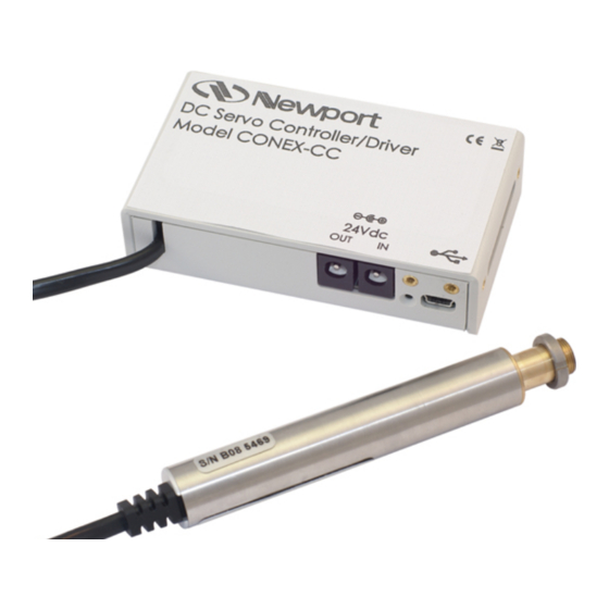
Summary of Contents for Newport CONEX-CC
- Page 1 CONEX-CC Single-Axis DC Motion with Controller/Driver Controller GUI Manual V2.0.x...
- Page 2 Original instructions. No part of this document may be reproduced or copied without the prior written approval of Newport Corporation. This document is provided for information only, and product specifications are subject to change without notice. Any change will be reflected in future publishings.
-
Page 3: Table Of Contents
1.0 Introduction ....................1 Purpose ..........................1 Overview .......................... 1 Controller State Diagram ....................2 2.0 Installation ..................... 3 Install CONEX-CC Graphical User Interface..............3 Launch GUI ........................3 3.0 Getting Started ....................4 Discover Instruments ......................4 4.0 User Interface ....................5 Configuration ........................ - Page 4 CONEX-CC Controller GUI Manual EDH0277En1041 — 10/17...
-
Page 5: Introduction
CONEX-CC Controller graphical user interface (GUI). Overview The CONEX-CC Controller GUI is a graphical user interface, that allows the user to interact with the CONEX-CC controller that is connected to stages with DC motors and encoder feedback. The user can initiate moves, change the state of the controller, adjust parameters, etc. -
Page 6: Controller State Diagram
CONEX-CC Controller GUI Manual Controller State Diagram The CONEX-CC controller is defined by the following state diagram. NOTE The position tracking is available only from the controller version 2.0.0 Controller’s LED display: NOT REFERENCED: If everything is OK then SOLID ORANGE. -
Page 7: Installation
Install CONEX-CC Graphical User Interface Following are steps to install CONEX-CC GUI. • For 32 bit, Select and launch “CONEX-CC Utility Installer Win32.exe”. For 64 bit, Select and launch “CONEX-CC Utility Installer Win64.exe”. • A window opens up showing Install welcome page. -
Page 8: Getting Started
NOTE When more than one CONEX-CC instrument is connected, this window allows the user to switch the instruments between X and Y axes. To discern a com port for a specific instrument, note their COM number in the Device Manager when the connection is added. -
Page 9: User Interface
Controller GUI will only log errors that are defined to be critical. The polling interval defines the number of milliseconds between each time the Controller GUI polls the CONEX-CC for the latest information. The user may change the polling interval by entering a value. Diagnostics Delay defines the time delay in milliseconds between each command sent from a text file. - Page 10 CONEX-CC Controller GUI Manual Configurable settings The following table describes all the settings that can be changed by the user. Parameter Description Values Default LoggingConfiguration Level Logging level. Trace Trace Trace is the most detailed of the settings and when this Detail setting is selected the Controller GUI logs everything.
- Page 11 CONEX-CC Controller GUI Manual This table describes mouse parameters for the MouseConfiguration section. MouseConfiguration EnterPositionTracking Activate the tracking mode. MouseButton/MouseEvent* Middle/Click ExitPositionTracking Desactivate the tracking mode. MouseButton/MouseEvent* Middle/Click SelectXaxis Select/Unselect X axis. MouseButton/MouseEvent* Left/Click SelectYaxis Select/Unselect Y axis. MouseButton/MouseEvent* Right/Click...
-
Page 12: Main
CONEX-CC Controller GUI Manual Main The Main tab displays the main controls in the Controller GUI like a virtual front panel. It is updated each time the polling interval timer expires. One Main tab by axis: Main X Main Y “Initialization and Configuration”... - Page 13 CONEX-CC Controller GUI Manual “Incremental Motion / PR-Move Relative” In the “Incremental Motion / PR-Move Relative” area, two increment values can be defined. For each defined increment, a relative move is performed in either the negative direction or positive direction.
-
Page 14: Tracking
CONEX-CC Controller GUI Manual Tracking The Tracking tab accesses the position tracking mode. The tracking position mode uses the mouse. NOTE In the tracking mode, the cursor is confined to the tracking position area. The “Enable/Disable” button executes the next enable command to change the controller status. - Page 15 CONEX-CC Controller GUI Manual Delete a memorized position: Select an item from the combo box, right-click on the mouse and select the “Delete” menu to delete the selected memorized position. Tracking panel and mouse The current position is represented by a black spot.
-
Page 16: Diagnostics
CONEX-CC Controller GUI Manual Diagnostics The Diagnostics tab allows the user to enter instrument commands and to view the history of commands that were sent and the responses that were received. This list of commands and the syntax of each command can be found in the user’s manual. -
Page 17: About
CONEX-CC Controller GUI Manual About The About tab displays the information about the Controller GUI and the connected instrument. It displays the Controller GUI name, version, and copyright information. It also displays the instrument model, instrument key (serial number) and firmware version for X and Y axes. - Page 18 CONEX-CC Controller GUI Manual EDH0277En1041 — 10/17...
-
Page 19: Service Form
CONEX-CC Controller GUI Manual Service Form Your Local Representative Tel.: __________________ Fax: ___________________ Name: _________________________________________________ Return authorization #: ____________________________________ (Please obtain prior to return of item) Company:_______________________________________________ Address: ________________________________________________ Date: __________________________________________________ Country: ________________________________________________ Phone Number: __________________________________________ P.O. Number: ____________________________________________ Fax Number: ____________________________________________... - Page 20 Visit Newport Online at: www.newport.com North America & Asia Europe Newport Corporation MICRO-CONTROLE Spectra-Physics S.A.S 1791 Deere Ave. 9, rue du Bois Sauvage Irvine, CA 92606, USA 91055 Évry CEDEX France Sales Tel.: (800) 222-6440 Sales e-mail: sales@newport.com Tel.: +33 (0)1.60.91.68.68 Technical Support e-mail: france@newport.com...
Need help?
Do you have a question about the CONEX-CC and is the answer not in the manual?
Questions and answers