Table of Contents
Advertisement
Quick Links
Advertisement
Table of Contents

Subscribe to Our Youtube Channel
Related Manuals for TYAN FT77D-B7109

Summary of Contents for TYAN FT77D-B7109
- Page 1 FT77D-B7109 Service Engineer’s Manual http://www.tyan.com...
- Page 2 http://www.tyan.com...
- Page 3 MITAC assumes no liability whatsoever, and ® disclaims any express or implied warranty, relating to sale and/or use of TYAN products including liability or warranties relating to fitness for a particular purpose or merchantability. MITAC retains the right to make changes to produce descriptions and/or specifications at any time, without notice.
- Page 4 There will be danger of explosion if battery is incorrectly replaced. Replace only with the same or equivalent type recommended by manufacturer. Dispose of used battery according to manufacturer instructions and in accordance with your local regulations. この装置は、クラスA情報技術装置です。この装置を家庭環境で使用すると電波妨 害を引き起こすことがあります。この場合には使用者が適切な対策を講ずるよう要 求されることがあります。 VCCI-A http://www.tyan.com...
-
Page 5: About This Manual
About this Manual This manual is intended for trained service technician/personnel with hardware knowledge of personal computers. It is aimed to provide you with instructions on installing your TYAN FT77D-B7109. How this guide is organized This guide contains the following parts:... - Page 6 Safety and Compliance Information Before installing and using TYAN FT77D-B7109, take note of the following precautions: ·Read all instructions carefully. ·Do not place the unit on an unstable surface, cart, or stand. ·Do not block the slots and opening on the unit, which are provided for ventilation.
-
Page 7: Safety Information
You must become familiar with the safety information in this guide before you install, operate, or service TYAN products. Symbols on Equipment Caution. This symbol indicates a potential hazard. - Page 8 · Make sure racks are coupled together if it is a multiple-rack installation. · Make sure the rack is level and stable before installing an appliance in the rack. · Make sure the leveling jacks are extended to the floor. http://www.tyan.com...
- Page 9 If you do not ground the Green/Yellow tab, it can cause an electrical shock due to high leakage currents. · Do not place objects on AC power cords or cables. Arrange them so that no http://www.tyan.com...
- Page 10 TYAN, your authorized TYAN partner, or their agents. Equipment Modifications · Do not make mechanical modifications to the system. TYAN is not responsible for the regulatory compliance of TYAN equipment that has been modified.
- Page 11 – Liquid has been spilled on the product or an object has fallen into the product. – The product has been exposed to rain or water. – The product has been dropped or damaged. – The product does not operate normally when you follow the operating instructions. http://www.tyan.com...
- Page 12 http://www.tyan.com...
-
Page 13: Table Of Contents
Table of Contents Chapter 1: Overview............... 17 About the TYAN FT77D-B7109 ..........17 Product Models ............... 18 Features .................. 19 Standard Parts List ..............31 1.4.1 Box Contents ..............31 1.4.2 Accessories ..............31 ... - Page 14 5.3.11 Option ROM Dispatch Policy ......... 146 5.3.12 PCI Subsystem Settings ..........148 5.3.13 Network Stack Configuration ......... 149 5.3.14 CSM Configuration ............151 5.3.15 USB Configuration ............153 Platform Configuration ............155 http://www.tyan.com...
- Page 15 Appendix I: How to recover UEFI BIOS ........225 Appendix II: Cable Connection Tables ........227 Appendix III: Fan and Temp Sensors ......... 231 Appendix IV: FRU Parts Table ............. 237 Appendix V: Technical Support ..........241 http://www.tyan.com...
- Page 16 NOTE http://www.tyan.com...
-
Page 17: Chapter 1: Overview
FT77D-B7109 not only empowers your company in nowadays IT demand but also offers a smooth path for future application usage. ® TYAN also offers the FT77D-B7109 in a version that can support up to fourteen (14) ® internal hot-swappable 2.5” SATA HDD/SSD or NVMe SSD with Intel RSTe 5.0 support. -
Page 18: Product Models
Product Models The system board within the Tyan Barebone is defined by the following models: B7109F77DV10E4HR-2T-N: Intel-based platform B7109F77DV14HR-2T-NF: Intel-based platform B7109F77DV14HR-2T-N: Intel-based platform Fabric Model Internal HDD Bays support FT77D-B7109 B7109F77DV10E4HR-2T-N (10) SATA + (4) NVMe SSD bays FT77D-B7109... -
Page 19: Features
Features TYAN FT77D-B7109 (B7109F77DV10E4HR-2T-N) Form Factor 4U Rackmount Chassis Model FT77D 30.31" x 17.24" x 6.93" Dimension (D x W x H) (770 x 438 x 176mm) System Motherboard S7109GM2NR-2T Gross Weight 45 kg (99.5 lbs) Net weight 26 kg (57.5 lbs) - Page 20 6 Channels per CPU Memory voltage 1.2V (8) PCI-E Gen3 x16 slots, PCI-E (2) PCI-E Gen3 x8 slots (one for Tyan OCP riser card only) Pre-install TYAN Riser Expansion Slots M2215-L8-1F Card M2093 w/ (2) PCI-E x8 SFF-8611 Pre-install TYAN Mezz...
- Page 21 Monitors temperature for CPU & Temperature memory & system environment Monitors voltage for CPU, memory, System Voltage chipset & power supply Monitoring Over temperature warning indicator, Fan & PSU fail LED indicator Others Watchdog timer support Server Onboard Chipset Onboard Aspeed AST2500 http://www.tyan.com...
- Page 22 90%, non-condensing at 35° C Humidity RoHS RoHS 6/6 Compliant (1) Web User's manual, Manual (1) Quick Installation Guide Package Installation CD (1) TYAN installation CD Contains (1) FT77D-B7109 w/NV Barebone Tesla-aware FW Barebone FT77D-B7109 (B7109F77DV14HR-2T-NF) Form Factor 4U Rackmount System...
- Page 23 200-240V AC input Efficiency PFC, 80 plus Platinum NOTE: When use 100V-127V AC input, the system does not support Redundancy redundant PSU operation if the total system load exceeds 20A (2000 Watts) Processor Socket Type / Q'ty LGA3647/ (2), *Socket-F support http://www.tyan.com...
- Page 24 Memory channel 6 Channels per CPU Memory voltage 1.2V (9) PCI-E Gen3 x16 slots, PCI-E (2) PCI-E Gen3 x8 slots (one for Tyan OCP riser card only) Expansion Slots Pre-install TYAN Riser M2215-L8-1F Card Port Q'ty (2) 10GbE ports, (1) PHY...
- Page 25 IPMI 2.0 compliant baseboard management controller (BMC), AST2500 iKVM Feature Server Supports storage over IP and Management remote platform-flash, USB 2.0 virtual hub 24-bit high quality video AST2500 IPMI Feature compression, 10/100/1000 Mb/s MAC interface BIOS Brand / ROM size AMI, 32MB http://www.tyan.com...
- Page 26 90%, non-condensing at 35° C Humidity RoHS RoHS 6/6 Compliant (1) Web User's manual, Manual (1) Quick Installation Guide Package Installation CD (1) TYAN installation CD Contains (1) FT77D-B7109 w/NV Barebone Tesla-aware FW Barebone TYAN FT77D-B7109 (B7109F77DV14HR-2T-N) Form Factor 4U Rackmount Chassis Model FT77D 30.31"...
- Page 27 20A (2000 Watts) Socket Type / Q'ty LGA3647/ (2) Intel Xeon Scalable Processor Supported CPU Series Family Processor Thermal Design Power Max up to 205W (TDP) wattage Up to 10.4/9.6 GT/s with Intel System Bus UltraPath Interconnect (UPI) support http://www.tyan.com...
- Page 28 Memory channel 6 Channels per CPU Memory voltage 1.2V (9) PCI-E Gen3 x16 slots, PCI-E (2) PCI-E Gen3 x8 slots (one for Tyan OCP riser card only) Expansion Slots Pre-install TYAN Riser M2215-L8-1F Card Port Q'ty (2) 10GbE ports, (1) PHY...
- Page 29 3.0/PnP/Wake on LAN, Boot from BIOS USB device/PXE via LAN/Storage, Feature User Configurable FAN PWM Duty Cycle, Console Redirection, ACPI sleeping states S4,S5, ACPI 6.1 Operating Please refer to our AVL support OS supported list System lists. Regulation FCC (DoC) Class A http://www.tyan.com...
- Page 30 - 40° C ~ 70° C (-40° F ~ 158° F) Environment In/Non-operating 90%, non-condensing at 35° C Humidity RoHS RoHS 6/6 Compliant (1) Web User's manual, Manual (1) Quick Installation Guide Package Installation CD (1) TYAN installation CD Contains (1) FT77D-B7109 w/NV Barebone Tesla-aware FW Barebone http://www.tyan.com...
-
Page 31: Standard Parts List
Standard Parts List This section describes FT77D-B7109 package contents and accessories. Open the box carefully and ensure that all components are present and undamaged. The product should arrive packaged as illustrated below. 1.4.1 Box Contents FT77D-B7109 Chassis Kit (1) 4U chassis ... -
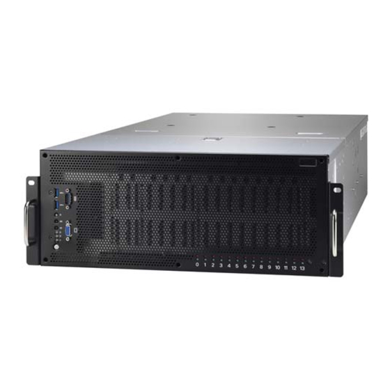
Page 32: About The Product
About the Product The following views show you the product. 1.5.1 System Front View http://www.tyan.com... - Page 33 *Warning LED Indication for 2+1 PSU Redundancy System Status System Warning LED All PSU present and plug AC cord when system power on One of PSU AC lose Amber solid on One of PSU not present Amber solid on http://www.tyan.com...
-
Page 34: System Rear View
LAN1 PCIE Slots NOTE: 1. With every two out of three PSUs can boot up the FT77D-B7109. 2. The FT77D-B7109 can support the redundant power under the condition when the voltage is 100~127V and the output power is less than 2000W, or the voltage is 200~240V and the output power is less than 3200W. - Page 35 PCIE Slot (M2093 pre-installed for NVMe SKU) NOTE: 1. With every two out of three PSUs can boot up the FT77D-B7109. 2. The FT77D-B7109 can support the redundant power under the condition when the voltage is 100~127V and the output power is less than 2000W, or the voltage is 200~240V and the output power is less than 3200W.
-
Page 36: Led Definitions
Green Blinking Green Solid On Link 1000 Mbps Green Solid On Amber Solid On (1Gbps) Active Green Blinking Amber Solid On NOTE: “Left” and “Right” are viewed from the rear panel. NOTE: LAN1/LAN2: Intel X550 LAN3: Realtek RTL8211E for IPMI http://www.tyan.com... - Page 37 AC present only 12VSB on (PS off) 1Hz Blinking Green or PS in Smart Redundant state Output ON and OK AC cord unplugged Warning: All PSUs have to be AC-ON at the same time before you power on the system. http://www.tyan.com...
-
Page 38: System Top View
M1284F77D-BP12E-14 HDD BP Board pre-installed M1713F77C-FPB Front Panel Board System Fans CPU0 CPU1 M7059F77C-D-PDB Power Distribution Board M7109F77D-D-PBP Power Backplane Board (2+1) Redundant Power Supply M2093 Riser Card (pre-installed for NVME SKU) NOTE: The system is pre-installed with S7109 motherboard. http://www.tyan.com... -
Page 39: Chapter 2: Setting Up
Caution! To avoid damaging the motherboard and associated components, use torque force within the range kgf/cm (4.35 ~ 6.09 lb/in) on each mounting screw for motherboard installation. Do not apply power to the board if it has been damaged. http://www.tyan.com... -
Page 40: Precautions
Working on a system that is connected to a power supply can be extremely dangerous. Follow the guidelines below to avoid damage to FT77D-B7109 or injury to yourself. Ground yourself properly before removing the top cover of the system. -
Page 41: Installing Motherboard Components
CPUs, memory modules and Add-on cards. 2.1.1 Removing the Chassis Cover Follow these instructions to remove FT77D-B7109 chassis cover. Loosen 2 thumb screws and 2 screws on the rear top cover. 2. Slide to lift up the rear top cover. - Page 42 4. Release the latch to lift up the front top cover from the chassis. http://www.tyan.com...
-
Page 43: Installing The Cpu And Heat Sink
Follow the steps below on installing CPUs and CPU heatsinks. Align and install the processor on the carrier. Carefully flip the heatsink. Then install the carrier assembly on the bottom of the heatsink and make sure the gold arrow is located in the correct direction. http://www.tyan.com... - Page 44 Carefully flip the heatsink. Align the heatsink with the CPU socket by the guide pins and make sure the gold arrow is located in the correct direction. Then place the heatsink onto the top of the CPU socket. http://www.tyan.com...
- Page 45 (1234). NOTE: When disassembling the heatsink, loosen the screws in reverse order (4321). Repeat the procedures described earlier to install the second processor and heatsink. Place the CPU air duct back and screw it to the chassis. http://www.tyan.com...
-
Page 46: Installing The Memory
Press the memory slot locking levers in the direction of the arrows as shown in the following illustration. Align the memory module with the slot. When inserted properly, the memory slot locking levers lock automatically onto the indentations at the ends of the module. http://www.tyan.com... - Page 47 http://www.tyan.com...
- Page 48 √ √ CPU1_DIMM_C1 √ √ √ √ √ √ √ √ √ CPU1_DIMM_D0 √ √ √ CPU1_DIMM_D1 √ √ √ √ √ √ √ √ CPU1_DIMM_E0 √ √ CPU1_DIMM_E1 √ √ √ √ √ √ √ CPU1_DIMM_F0 √ CPU1_DIMM_F1 http://www.tyan.com...
- Page 49 4. Dual-rank DIMMs are recommended over single-rank DIMMs. 5. Un-buffered DIMM can offer slightly better performance than registerd DIMM if populating only a single DIMM per channel. 6. Always install with CPU0 Socket and DIMM_0 Slot first, following the alphabetical order. http://www.tyan.com...
-
Page 50: Installing Expansion Cards
Follow these instructions to install the PCIE cards. Using GPU Bracket Locate the PCI-E Gen.3 x16 slot on the motherboard. Unscrew to take out the dummy brackets. Screw the GPU bracket to the GPU card and connect the GPU PWR cable. http://www.tyan.com... - Page 51 Insert the GPU card into the PCIE Gen. 3 slot and screw the GPU card to the chassis. Connect the GPU PWR cable to the Power Distribution Board. http://www.tyan.com...
- Page 52 Using Card Guide Insert the card guide onto the power distribution board bracket. Insert the full-length, full-height PCIE card into the PCIE Gen3 x16 slot and screw it firmly to the chassis. http://www.tyan.com...
-
Page 53: Installing The Mezzanine Card
2.1.5 Installing the Mezzanine Card Follow these instructions to install the Mezzanine Card. Unscrew the dummy bracket. Pull the dummy bracket to slide it out. http://www.tyan.com... - Page 54 Insert a Mezzanine card associated with tray into the slot and screw it to the chassis. http://www.tyan.com...
-
Page 55: Installing Hard Drives
2.1.6 Installing Hard Drives The FT77D-B7109 supports fourteen 2.5” HDD/SSD. Follow these instructions to install a hard drive. Pull the HDD tray out from the chassis. Remove 4 screws to detach the HDD tray bracket. Place a HDD/SSD into the drive tray. Use four screws to secure the HDD/SSD. -
Page 56: Rack Mounting
The users have to prepare two screws and two nuts on their own for rack mounting. 2.2.1 Installing the Server in a Rack Follow these instructions to mount the FT77D-B7109 into an industry standard 19” rack. Note: Before mounting FT77D-B7109 in a rack, ensure that all internal components have been installed and that the unit has been fully tested. -
Page 57: Installing The Inner Rails To The Chassis
2.2.2 Installing the inner Rails to the Chassis Screw the mounting ear to each side of FT77D-B7109 as shown using 4 screws from the supplied screws kit. Press the latch key to draw out the inner rails from sliding rails. - Page 58 Secure the screws to both sides of the chassis. http://www.tyan.com...
-
Page 59: Installing The Outer Rails To The Rack
2.2.3 Installing the Outer Rails to the Rack Please note to prepare two nuts and two screws before you start the work. Secure the outer rails to the rack. http://www.tyan.com... -
Page 60: Rack Mounting The Server
2.2.4 Rack mounting the Server Lift the chassis and then insert the inner slide rails into the outer rails. Push the chassis in. Screw the mounting ears of chassis to the rack. http://www.tyan.com... - Page 61 Press the latch keys on both sides simultaneously to pull the system out. http://www.tyan.com...
- Page 62 NOTE http://www.tyan.com...
-
Page 63: Chapter 3: Replacing Pre-Installed Components
This chapter explains how to replace the pre-installed components, including the S7109 Motherboard, M1713F77C-FPB Front Panel Board, M1809F77A-FB Board, M2215-L8-1F Riser Card, M1284F77D-BP12E-14 HDD Backplane Board, M7109F77D-D-PBP Power Backplane Board, M7059F77C-D-PDB Power Distribution Board, System Fan and Power Supply etc. Disassembly Flowchart The following flowchart outlines the disassembly procedure. http://www.tyan.com... -
Page 64: Removing The Cover
Removing the Cover Follow Chapter 2.1.1 to remove the cover of FT77D-B7109. Replacing the Power Supply To replace the power supply follow these instructions. Press the tab as shown to pull out the power. Free the power from the power cage. -
Page 65: Replacing The Front Panel Board
Replacing the Front Panel Board Follow these instructions to replace the M1713F77C-FPB Front Panel Board. Disconnect the USB3.0 and Front Panel Cable. Unscrew to remove the front panel board module. http://www.tyan.com... - Page 66 Loosen three screws to take out the front panel board. Remove the ID Button cap, LED sponge and LED Lens to reinstall in the new Front Panel Board. Follow the steps described earlier in reverse order to reinstall the front panel board module. http://www.tyan.com...
-
Page 67: Front Panel Board Features
BTN: PWR BTN w/LED, Reset BTN, ID BTN, NMI Specifications LED: PWR LED (green), Warning LED (amber), ID LED (blue), HDD LED (green), LAN active LED (green) I/O: (2) Type-A USB3.0 Connector Temperature sensor inlet build-in http://www.tyan.com... -
Page 68: Replacing The Fan Board
Replacing the Fan Board Follow these instructions to replace the M1809F77A-FB Fan Board. Remove all Fan modules. Unscrew the fan cage. Lift up the fan cage. http://www.tyan.com... - Page 69 Disconnect all cables from the Fan Board. Unscrew to replace with a new Fan Board. Follow the steps in reverse order to reinstall the Fan Board. http://www.tyan.com...
-
Page 70: Fan Board Features
3.6.1 Fan Board Features M1809F77A-FB Fan Board Support (6) 120x38 mm system FAN (4) 4-pin B4P RA PWR Connector (run DC+12V) Specifications (6) 4-pin Hot-swap FAN Connector (1) 20-pin barebone system FAN connector to MB FAN Sequence http://www.tyan.com... -
Page 71: Replacing The Hdd Backplane Board
Follow these instructions to replace the M1284F77D-BP12E-14 HDD Backplane Board. Remove the screws on both sides of the chassis. Remove all HDD trays from the HDD cage. Refer to Section 3.5 Replacing the Front Panel Board to take out the Front Panel Board Tray. http://www.tyan.com... - Page 72 Unscrew the Front COM and VGA Ports. Disconnect the COM and VGA cables. Unscrew to release the HDD Cage. http://www.tyan.com...
- Page 73 Lift up the HDD cage from the chassis Disconnect all cables connected to the HDD BP Board. NVME SKU (R) SATA SKU (R) NVME & SATA SKU (L) http://www.tyan.com...
- Page 74 Unscrew the HDD BP Board from the chassis. 10. Take out the HDD BP Board to replace with a new one. Follow the procedures described earlier in reverse order to reinstall the HDD BP Board and HDD cage. http://www.tyan.com...
-
Page 75: Hdd Bp Board Features
Support 14 hot-swappable 2.5” HDD/SSD or NVMe SSD, speed up to 12Gb/s Onboard HDD LED indication for HDD status (Active/Status) Specifications (3) B4P HDD PWR Connector (2) 7-pin SATA Connector (3) Mini-SAS HD Connector (2) SFF-8611 OCuLink connectors HDD/SSD sequence Port sSATA4 sSATA5 sSATA0~3 SATA0~7 http://www.tyan.com... -
Page 76: Replacing Power Distribution Board
Follow these instructions to replace the M7059F77C-D-PDB Power Distribution Board. Disconnect the PWR cable. Unscrew the M7059F77C-D-PDB Power Distribution Board. Remove the power distribution board for replacement. Follow the steps described earlier in reverse order to reinstall the power distribution board into the chassis. http://www.tyan.com... -
Page 77: Power Distribution Board Features
3.8.1 Power Distribution Board Features M7059F77C-D-PDB Power Distribution Board (1) 24S+6P RA Connector to M7109F77D-D-PBP Specifications (1) ATX 8-pin PWR Connector to Fan Board (16) ATX 8-pin PWR Connector to GPU card http://www.tyan.com... -
Page 78: Replacing The Riser Card
Replacing the Riser Card Follow these instructions to replace the M2215-L8-1F Riser Card. Pull out all power supply units and unscrew the Mezz card module. Unscrew the power supply cage. Unscrew the power supply cage. http://www.tyan.com... - Page 79 Lift up the power supply cage. Loosen the screws to lift up the bracket. Unscrew to replace a new riser card. Follow the steps described earlier in reverse order to reinstall the riser card bracket. http://www.tyan.com...
-
Page 80: Riser Card Feature
3.9.1 Riser card Feature M2215-L8-1F Riser Card Form Factor W31.85 x L94 (mm), 4-layer PCB Specification (1) PCI-E Gen3 x8 Slot for non-standard add-on card http://www.tyan.com... -
Page 81: 3.10 Replace The Power Backplane Board
Power Backplane Board. Unscrew the Power Backplane Board Tray. Lift up the PBP Board Tray. Unscrew the M7109F77D-D-PBP from the bracket and replace with a new one. Follow the steps described earlier in reverse order to reinstall the power backplane board. http://www.tyan.com... -
Page 82: 3.10.1 Power Backplane Board Features
3.10.1 Power Backplane Board Features Front View Rear View M7109F77D-D-PBP Power Backplane Board (3) Power supply Connector for DPS-1600CB A (1) 24S+6P RA Connector to MB Specifications (1) 24S+6P Connector to M7059F77C-D-PDB (1) ATX 8-pin PWR Connector http://www.tyan.com... -
Page 83: 3.11 Replacing The Motherboard
3.11 Replacing the Motherboard After removing all of the aforementioned cables and components, follow these instructions to remove the motherboard from the chassis. Loosen the screws securing the PDB Bracket to the chassis. http://www.tyan.com... - Page 84 Unscrew the OCP Riser Card Bracket. Refer to Section 3.9 Replacing the Riser Card and 3.10 Replacing the Power Backplane Board to remove the Power Supply Cage and the PBP Tray. (SATA SKU) Disconnect all cables. (NVME SKU) Disconnect all cables. http://www.tyan.com...
- Page 85 Unscrew the motherboard to lift it up for replacement. http://www.tyan.com...
- Page 86 NOTE http://www.tyan.com...
-
Page 87: Chapter 4: Motherboard Information
Caution! To avoid damaging the motherboard and associated components, use torque force within the range kgf/cm (4.35 ~ 6.09 lb/in) on each mounting screw for motherboard installation. Do not apply power to the board if it has been damaged. http://www.tyan.com... -
Page 88: Board Image
Board Image S7109 This picture is representative of the latest board revision available at the time of publishing. The board you receive may not look exactly like the above picture. http://www.tyan.com... -
Page 89: Block Diagram
Block Diagram S7109 Block Diagram http://www.tyan.com... -
Page 90: Motherboard Mechanical Drawing
Motherboard Mechanical Drawing http://www.tyan.com... -
Page 91: Board Parts, Jumpers And Connectors
The board you receive may not look exactly like the above diagram. The DIMM slot numbers shown above can be used as a reference when reviewing the DIMM population guidelines shown later in the manual. For the latest board revision, please visit our web site at http://www.tyan.com. http://www.tyan.com... - Page 92 26. 4-pin Fan Connector (CPU0_FAN) 27. 7-pin Vertical SATA3.0 Connector 6. BIOS Socket (BIOS_SOCKET1) (SATA) (PCH_SSATA_5) 28. 7-pin Vertical SATA3.0 Connector 7. TYAN Module Header (DBG_HD1) (SATA) (PCH_SSATA_4) 29. 4-pin HDD Backplane Power Connector 8. Reset Button (RST_BTN1) (D4P_PW1) 9. Power Button (PWR_BTN1) 30.
- Page 93 PCI-E 3.0x8 slot (open-end type, (x8 link, open-end type, only for J25) S7109GM2NR-8X-2T) (J16/J17/J18/J19/J20/J21/J22/J23) PCI-E 3.0x8 slot (open-end type) (J48, only for Tyan riser card) Jumper Legend OPEN - Jumper OFF Without jumper cover CLOSED - Jumper ON With jumper cover...
- Page 94 J60: Front Panel Header Signal Signal PWRLED+ FP Power(3.3V standby) ID_LED+ PWRLED-(GND) ID_LED-(GND) HD_LED+ Fault LED1- HD_LED- Fault LED2- Power Switch+ LAN1_ACTIVE_LED+ Power Switch-(GND) LAN1_ACTIVE_LED- Reset Switch+ SMB_DATA Reset Switch-(GND) SMB_CLK ID Switch+ INTRUDER# TEMP Sensor LAN2_ACTIVE_LED+ NMI Switch# LAN2_ACTIVE_LED - http://www.tyan.com...
- Page 95 3. Move the jumper cap to close Pin_2 and Pin_3 for several seconds to Clear CMOS. 4. Put jumper cap back to Pin_1 and Pin_2 (Default setting). 5. Reconnect power connectors to the motherboard and power on system. Clear CMOS http://www.tyan.com...
- Page 96 System identified System not identified NOTE: The ID LED can be activated remotely using IPMI. http://www.tyan.com Please visit the TYAN Web Site at to download the latest IPMI Configuration Guide for more details. J58/J59: Vertical Type-A USB Connector Signal USB 5V Power...
- Page 97 JP6: BIOS Recovery Mode Jumper Pin 1-2 Closed: Normal (Default) Pin 2-3 Closed: Recovery CMOS JP7: ME Firmware Update Jumper Pin 1-2 Closed: Open (Default) Pin 2-3 Closed: ME Force Update http://www.tyan.com...
-
Page 98: Thermal Interface Material
CPU lid (applying too much will actually reduce the cooling). NOTE: Always check with the manufacturer of the heat sink & processor to ensure that the thermal interface material is compatible with the processor and meets the manufacturer’s warranty requirements. http://www.tyan.com... -
Page 99: Tips On Installing Motherboard In Chassis
Be especially careful to look for extra stand-offs. If there are any stand-offs present that are not aligned with a mounting hole on the motherboard, it will likely short components on the back of the motherboard when installed. This will cause malfunction and/or damage to your motherboard. http://www.tyan.com... - Page 100 Some chassis include plastic studs instead of metal. Although the plastic studs are usable, MITAC recommends using metal studs with screws that will fasten the motherboard more securely in place. Below is a chart detailing what the most common motherboard studs look like and how they should be installed. http://www.tyan.com...
-
Page 101: Installing The Memory
Installing the Memory Before installing memory, ensure that the memory you have is compatible with the motherboard and processor. Check the TYAN Web site at http://www.tyan.com details of the type of memory recommended for your motherboard. This platform supports (12)+(12) DDR4 RDIMM/RDIMM 3DS/LRDIMM/LRDIMM3DS 2666 ... - Page 102 CPU0_DIMM_D0 √ √ √ CPU0_DIMM_D1 √ √ √ √ √ √ √ √ CPU0_DIMM_E0 √ √ CPU0_DIMM_E1 √ √ √ √ √ √ √ CPU0_DIMM_F0 √ CPU0_DIMM_F1 CPU1_DIMM_A0 CPU1_DIMM_A1 CPU1_DIMM_B0 CPU1_DIMM_B1 CPU1_DIMM_C0 CPU1_DIMM_C1 CPU1_DIMM_D0 CPU1_DIMM_D1 CPU1_DIMM_E0 CPU1_DIMM_E1 CPU1_DIMM_F0 CPU1_DIMM_F1 http://www.tyan.com...
- Page 103 4. Dual-rank DIMMs are recommended over single-rank DIMMs. 5. Un-buffered DIMM can offer slightly better performance than registerd DIMM if populating only a single DIMM per channel. 6. Always install with CPU0 Socket and DIMM_0 Slot first, following the alphabetical order. http://www.tyan.com...
- Page 104 http://www.tyan.com...
- Page 105 √ √ CPU1_DIMM_C1 √ √ √ √ √ √ √ √ √ CPU1_DIMM_D0 √ √ √ CPU1_DIMM_D1 √ √ √ √ √ √ √ √ CPU1_DIMM_E0 √ √ CPU1_DIMM_E1 √ √ √ √ √ √ √ CPU1_DIMM_F0 √ CPU1_DIMM_F1 http://www.tyan.com...
- Page 106 4. Dual-rank DIMMs are recommended over single-rank DIMMs. 5. Un-buffered DIMM can offer slightly better performance than registerd DIMM if populating only a single DIMM per channel. 6. Always install with CPU0 Socket and DIMM_0 Slot first, following the alphabetical order. http://www.tyan.com...
-
Page 107: Mainboard Led Definition
Mainboard LED Definition http://www.tyan.com... - Page 108 Signal + 3V_AUX Rear ID IDLED_BTN1 State Description Green Signal CPU0 State Description P0_PG_LED1 PWOK The LED shuts off when the power of CPU0 is abnormal. The LED lights up when the Green power of CPU0 is normally. http://www.tyan.com...
- Page 109 CPU1 is abnormal. The LED lights up when the Green power of CPU1 is normally. Signal + 3V State Description ATX_PG_LED1 PWROK The LED shuts off when the PSU is normal. The LED lights up when the Green PSU is abnormally. http://www.tyan.com...
-
Page 110: Finishing Up
In the rare circumstance that you have experienced difficulty, you can find help by asking your vendor for assistance. If they are not available for assistance, please find setup information and documentation online at our website or by calling your vendor’s support line. http://www.tyan.com... -
Page 111: Chapter 5: Bios Setup
The table below shows how to navigate in the setup program using the keyboard. Function Left/Right Arrow Keys Change from one menu to the next Up/Down Arrow Keys Move between selections Enter Open highlighted section PgUp/PgDn Keys Change pages Change options Exit http://www.tyan.com... -
Page 112: Getting Help
The following pages provide the details of BIOS menu. Please be noticed that the BIOS menu are continually changing due to the BIOS updating. The BIOS menu provided are the most updated ones when this manual is written. Please visit TYAN’s website at http://www.tyan.com for the information of BIOS updating. -
Page 113: Main Menu
It displays BIOS related information. Memory Information This displays the total memory size. System Language Choose the system default language. English System Date Set the Date. Use Tab to switch between Date elements. Default Ranges: Year: 2005-2099 Months: 1-12 Days: dependent on month http://www.tyan.com... - Page 114 System Time Set the Time. Use Tab to switch between Time elements. http://www.tyan.com...
-
Page 115: Advanced Menu
Intel® Virtual RAID on CPU This formset allows the user to manage Intel® Virtual RAID on CPU. Trusted Computing Trusted Computing Settings. ACPI Settings System ACPI Parameters. OnBoard Device Configuration OnBoard Device and Function Configuration. Hardware Health Configuration Hardware Health Configuration. http://www.tyan.com... - Page 116 Serial Port Console Redirection. Option ROM Dispatch Policy Option ROM Dispatch Poligy. PCI Subsystem Settings PCI, PCI-X and PCI Express Settings. Network Stack Configuration Network Stack Settings. CSM Configuration CSM configuration: Enable/Disable, Option ROM execution settings, etc. USB Configuration USB Configuration Parameters. http://www.tyan.com...
-
Page 117: Iscsi Configuration
Select Advanced Network Stack Configuration Network Stack [Enabled] Step 3. Save changes and reboot. iSCSI Initiator Name The worldwide unique name of iSCSI Initiator. Only IQN format is accepted. Enter [iqn.xxx]. xxx ranges from 4 to 223. http://www.tyan.com... - Page 118 5.3.1.1 Add an Attempt Read only. NOTE: Only LAN1 supports iSCSI function. http://www.tyan.com...
- Page 119 IP4 / IP6 / Autoconfigure Connection Retry Count The minimum value is 0 and the maximum is 16. 0 means no retry. Connection Establishing Timeout The timeout value in milliseconds. The minimum value is 100 milliseconds and the maximum is 20 seconds. http://www.tyan.com...
- Page 120 Target Port Target Port. Boot LUN Hexadecimal representation of the LU number. Examples are: 4752-3A4F-6b7e-3F99, 6734-9-156f-127, 4186-9. Authentication Type Authentication method: CHAP, Kerberos, or None. CHAP / None Save Changes Must reboot system manually for changes to take place. http://www.tyan.com...
- Page 121 Delete Attempts Attempt 1 MAC: 34:12:78:56:00:00, PFA: Bus 1/ Dev 0 / Func 0, iSCSI mode: Disabled, IP version: IP4. Disabled / Enabled Commit Changes and Exit Commit Changes and Exit. Discard Changes and Exit Discard Changes and Exit. http://www.tyan.com...
- Page 122 Change the order of Attempts using +/- keys. Use arrow keys to select the attempt then press +/- to move the attempt up/down in the attempt order list. Attempt 1 / Attempt # Commit Changes and Exit Commit Changes and Exit. Discard Changes and Exit Discard Changes and Exit. http://www.tyan.com...
-
Page 123: Intel® Virtual Raid On Cpu
Suppose the card is installed in CPU0 Slot 3, then Intel® VMD for Volume Management Device for PStack0 will be set to [Enabled]. Step 3. Save changes and reboot. All Intel VMD Controllers Select to see more information about the Intel VMD Controllers. http://www.tyan.com... - Page 124 5.3.2.1 All Intel VMD Controllers Create RAID Volume This page allows you to create a RAID volume. Non-RAID Physical Disks Read only. http://www.tyan.com...
- Page 125 Enable RAID spanned over VMD Controllers Enter RAID spanned over VMD Controllers. blank / X Port 0, VMD0, INTEL SSDPE2MD400G4 X – to Select Disk. blank / X Port 1, VMD1, INTEL SSDPEDME400G4 X – to Select Disk. blank / X http://www.tyan.com...
- Page 126 Create a volume with the settings specified above. NOTE: For Create Volume to be configurable, the following items Enable RAID spanned over VMD Controllers, Port 0, VMD0, INTEL SSDPE2MD400G4 and Port 1, VMD1, INTEL SSDPEDME400G4 must be set to [X]. http://www.tyan.com...
- Page 127 5.3.2.1.1.1 Create Volume Press ‘y’ to create, ‘n’ to discard. Volume0, RAID0(Stripe), 708.0GB, Normal Select to see more information about the RAID volume. http://www.tyan.com...
- Page 128 Volume0, RAID0(Stripe), 708.0GB, Normal 5.3.2.1.1.1.1 Read only. http://www.tyan.com...
- Page 129 Delete 5.3.2.1.1.1.1.1 Delete the RAID Volume Deleting a volume will reset the disks to non-RAID. Yes / No http://www.tyan.com...
- Page 130 5.3.2.1.2 Port 0, VMD0, INTEL SSDPE2MD400G4 SN: xxxx, … Port 1, VMD1, INTEL SSDPEDMD400G4 SN: xxxx, …. Read only. http://www.tyan.com...
-
Page 131: Trusted Computing
5.3.3 Trusted Computing Security Device Support Enables or Disables BIOS support for security device. O.S. will not show Security Device. TCG EFI protocol and INT1A interface will not be available. Enabled / Disabled http://www.tyan.com... -
Page 132: Acpi Settings
ACPI Settings Enable ACPI Auto Configuration Enable or disable BIOS ACPI Auto Configuration. Disabled / Enabled Enable Hibernation Enable or disable System ability to Hibernate (OS/S4 Sleep State). This option may not be effective with some OS. Disabled / Enabled http://www.tyan.com... -
Page 133: Onboard Device Configuration
Onboard Lan X550 Enable/Disable onboard Lan X550. Disabled / Enabled Chassis Intrusion detect ENABLED: when a chassis open event is detected, the BIOS will record the event. Disabled / Enabled NMI Button Enable or Disable NMI button. Disabled / Enabled http://www.tyan.com... -
Page 134: Hardware Health Configuration
5.3.6 Hardware Health Configuration Auto Fan Control Auto Fan Control Help. Disabled / Enabled BMC Alert Beep Enable/Disable BMC Alert Beep. On / Off PMBus Support PMBus Support. Enabled / Disabled http://www.tyan.com... - Page 135 5.3.6.1 Sensor Data Register Monitoring When you enter the Sensor Data Register Monitoring submenu, you will see the following dialog window pop out. Please wait 8~10 seconds. NOTE: SDR can not be modified. Read only. http://www.tyan.com...
-
Page 136: Pcie Slot Configuration
5.3.7 PCIe Slot Configuration PCIe Slot J3 Selects PCIe port Bifurcation for selected slot(s). x4x4x4x4 / x4x4x8 / x8x4x4 / x8x8 / x16 http://www.tyan.com... -
Page 137: Ast2500 Super Io Configuration
5.3.8 AST2500 Super IO Configuration Super IO Chip Read only. http://www.tyan.com... - Page 138 / IO=3F8h, IRQ=3, 4, 5, 6, 7, 9, 10, 11, 12; / IO=2F8h; IRQ=3, 4, 5, 6, 7, 9, 10, 11, 12; / IO=3E8h, IRQ=3, 4, 5, 6, 7, 9, 10, 11, 12; / IO=2E8h, IRQ=3, 4, 5, 6, 7, 9, 10, 11, 12; http://www.tyan.com...
-
Page 139: S5 Rtc Wake Settings
Select 0-23. For example enter 3 for 3am and 15 for 3pm. Wake up minute Select 0-59 for Minute. Wake up second Select 0-59 for Second. When Wake system from S5 is set to [Dynamic Time] Wake up Minute increase 1-5. http://www.tyan.com... -
Page 140: 5.3.10 Serial Port Console Redirection
COM1 / Serial Port for Out-Of-Band Management/Windows Emergency Services (EMS) Console Redirection Settings The settings specify how the host computer (which the user is using) will exchange data. Both computers should have the same or compatible settings. Legacy Console Redirection Settings Legacy Console redirection settings. http://www.tyan.com... - Page 141 0 if the num of 1’s in the data bits is even. Odd: parity bit is 0 if the num of 1’s in the data bits is odd. Mark: parity bit is always 1. Space: parity bit is always 0. Mark and Space parity do not allow for error detection. None / Even / Odd / Mark / Space http://www.tyan.com...
- Page 142 Redirection after BIOS POST The settings specify if BootLoader is selected than Legacy console redirection is disabled before booting to Legacy OS. Default value is Always Enable which means Legacy Console Redirection is enabled for Legacy OS. Always Enable / BootLoader http://www.tyan.com...
- Page 143 5.3.10.2 Legacy Console Redirection Settings Legacy Serial Redirection Port Select a COM port to display redirection of Legacy OS and Legacy OPROM Messages. COM1 http://www.tyan.com...
- Page 144 VT-UTF8 / VT100 / VT100+ / ANSI Bits per Second Select serial port transmission speed. The speed must be matched on the other side. Long or noisy lines may require lower speeds. 115200 / 9600 / 19200 / 57600 http://www.tyan.com...
- Page 145 ‘start’ signal can be sent to restart the flow. Hardware flow control uses two wires to send start/stop signal. None / Hardware RTS/CTS / Software Xon/Xoff Data Bits / Parity / Stop Bits Read only. http://www.tyan.com...
-
Page 146: 5.3.11 Option Rom Dispatch Policy
5.3.11 Option ROM Dispatch Policy OnBoard LAN1 (X550) Onboard Device has: UEFI [X] Legacy [X] Emabed ROM(s). VIDx8086; DIDx1563 @ s0/Bx1/Dx0/Fx0. Enabled / Disabled OnBoard LAN2 (X550) Onboard Device has: UEFI [X] Legacy [X] Emabed ROM(s). VIDx8086; DIDx1563 @ s0/Bx1/Dx0/Fx1. Enabled / Disabled http://www.tyan.com... - Page 147 Enable or Disable Option ROM execution for selected Slot. Disabled / Enabled Storage Card Empty Enable or Disable Option ROM execution for selected Slot. Disabled / Enabled Slot J3 Empty Enable or Disable Option ROM execution for selected Slot. Disabled / Enabled http://www.tyan.com...
-
Page 148: 5.3.12 Pci Subsystem Settings
Enables or Disables 64bit capable Devices to be Decoded in Above 4G Address Space (Only if System Supports 64 bit PCI Decoding). Enabled / Disabled SR-IOV Support If system has SR-IOV capable PCIe Devices, this option Enables or Disables Single Root IO Virtualization Support. Enabled / Disabled http://www.tyan.com... -
Page 149: 5.3.13 Network Stack Configuration
Enable Ipv4 HTTP Boot Support. If disabled IPV4 HTTP boot option will not be created. Disabled / Enabled Ipv6 PXE Support Enable Ipv6 PXE Boot Support. If disabled IPV6 PXE boot option will not be created. Disabled / Enabled http://www.tyan.com... - Page 150 Enable Ipv6 HTTP Boot Support. If disabled IPV6 HTTP boot option will not be created. Disabled / Enabled PXE boot wait time Wait time to press ESC key to abort the PXE boot. Media detect count Number of times presence of media will be checked. http://www.tyan.com...
-
Page 151: 5.3.14 Csm Configuration
Legacy / Do not launch / UEFI Storage Controls the execution of UEFI and Legacy Storage OpROM. Legacy / Do not launch / UEFI Video Controls the execution of UEFI and Legacy Video OpROM Legacy / Do not launch / UEFI http://www.tyan.com... - Page 152 Other PCI Devices Determines OpROM execution policy for devices other than Network, Storage, or Video. Legacy / Do not launch / UEFI http://www.tyan.com...
-
Page 153: 5.3.15 Usb Configuration
XHCI Hand-off This is a workaround for OSes without XHCI hand-off support. The XHCI ownership change should be claimed by XHCI driver. Enabled / Disabled USB Mass Storage Driver Support Enable/Disable USB Mass Storage Driver Support. Enabled / Disabled http://www.tyan.com... - Page 154 Maximum time the device will take before it properly reports itself to the Host Controller. ‘AUTO’ uses default value: for a Root port it is 100 ms, for a Hub port the delay is taken from Hub descriptor. Auto / Manual http://www.tyan.com...
-
Page 155: Platform Configuration
Platform Configuration PCH Configuration Displays and provides option to change the PCH Settings. Server ME Configuration Configure Server ME Technology Parameters. http://www.tyan.com... -
Page 156: Pch Configuration
Enable/Disable Intel® IO Controller Hub devices. PCI Express Configuration PCI Express Configuration settings. PCH SATA Configuration SATA devices and settings. PCH sSATA Configuration sSATA devices and settings. USB Configuration USB Configuration Settings. PCH DFX Configuration PCH DFX Configuration Options. http://www.tyan.com... - Page 157 5.4.1.1 PCH Devices PCH state after G3 Select S0/S5 for ACPI state after a G3. Power On / Power Off / Last State http://www.tyan.com...
- Page 158 5.4.1.2 PCI Express Configuration PCI Express Root Port 1 ~ Port 20 PCI Express Root Port 1 ~ Port 20 Settings. http://www.tyan.com...
- Page 159 PCI Express L1 Substates settings. Disabled / L1.1 / L1.2 / L1.1 & L1.2 PCIe Speed Configure PCIe Speed. Auto / Gen1 / Gen2 / Gen3 Max Payload Size PCIE Max Payload Size Selection. MPL 128B / MPL 256B http://www.tyan.com...
- Page 160 Configure SATA as Determines how SATA controller(s) operate. AHCI / RAID SATA Port 0/1/2/3/4/5/6/7 & Software Preserve Read Only Port 0 Enable or Disable SATA Port. Disabled / Enabled Hot Plug Designates this port as Hot Pluggable. Disabled / Enabled http://www.tyan.com...
- Page 161 Otherwise all drives spin up at boot. Disabled / Enabled SATA Device Type Identify the SATA port is connected to Solid State Drive or Hard disk Drive. Hard Disk Drive / Solid State Drive http://www.tyan.com...
- Page 162 Configure sSATA as Determines how SATA controller(s) operate. AHCI / RAID sSATA Port 0/1/2/3/4/5 & Software Preserve Read Only Port 0 Enable or Disable SATA Port. Disabled / Enabled Hot Plug Designates this port as Hot Pluggable. Disabled / Enabled http://www.tyan.com...
- Page 163 Otherwise all drives spin up at boot. Disabled / Enabled SATA Device Type Identify the SATA port is connected to Solid State Drive or Hard disk Drive. Hard Disk Drive / Solid State Drive http://www.tyan.com...
- Page 164 5.4.1.5 USB Configuration XHCI Idle L1 Enabled XHCI Idle L1. Disabled to workaround USB3 hot plug will fail after 1 hot plug removal. Please put the system to G3 for the new settings to take effect. Enabled / Disabled http://www.tyan.com...
- Page 165 Enables/Disables ADR on Host Partition Reset Enabled / Disabled Enable/Disable ADR Timer Held-off for DEBUG PURPOSES ONLY! Enabled / Held-off ADR timer expire time Select proper ADR timer value: 25uS,50uS,100uS or 0. 25 uS / 50 uS / 100 uS / 0 uS http://www.tyan.com...
- Page 166 ADR timer multiplier Select proper ADR timer multiplier: x1,8,24,40,56,64,72,80,88,96. x1 / x8 / x24 / x40 / x56 / x64 / x72 / x80 / x88 /x96 http://www.tyan.com...
-
Page 167: Miscellaneous Configuration
5.4.2 Miscellaneous Configuration Active Video Select active video type. Onboard Device / Offboard Device http://www.tyan.com... -
Page 168: Server Me Configuration
5.4.3 Server ME Configuration Read only. http://www.tyan.com... -
Page 169: Socket Configuration
Displays and provides option to change the UPI Settings. Memory Configuration Displays and provides option to change the Memory Settings. IIO Configuration Displays and provides option to change the IIO Settings. Advanced Power Management Configuration Displays and provides option to change the Power Management Settings. http://www.tyan.com... -
Page 170: Processor Configuration
This should be enabled in order to boot legacy OSes that cannot support CPUs with extended CPUID functions. Disabled / Enabled Execute Disable Bit When disabled, forces the XD feature flag to always return 0. Disabled / Enabled Enable Intel® TXT Enables Intel® TXT. Disabled / Enabled http://www.tyan.com... - Page 171 Hardware Prefetcher MLC Streamer Prefetcher (MSR 1A4h Bit[0]). Enabled / Disabled Adjacent Cache Prefetch MLC Spatial Prefetcher (MSR 1A4h Bit[1]). Enabled / Disabled Extended APCI Enable/Disable extended APIC support. Disabled / Enabled AES-NI Enable/Disable AES-NI support. Enabled / Disabled http://www.tyan.com...
-
Page 172: Common Refcode Configuration
Selects the allocation size used to assign mmioh resources. Total mmioh space can be up to 32xgranularity. Per stack mmioh resource assignments are multiples of the granularity where 1 unit per stack is the default allocation. 1G / 4G / 16G / 64G / 256G / 1024G http://www.tyan.com... - Page 173 Numa Enable or Disable Non uniform Memory Access (NUMA). Disabled / Enabled http://www.tyan.com...
-
Page 174: Upi Configuration
5.5.3 UPI Configuration UPI General Configuration Displays and provides option to change the UPI General Settings. http://www.tyan.com... - Page 175 Slow / Fast Link Frequency Select Allows for selecting the UPI Link Frequency. 9.6GB/s / 10.4GB/s / Auto / Use Per Link Setting Link L0p Enable Disabled / Enable / Auto Link L1 Enable Disabled / Enable / Auto http://www.tyan.com...
- Page 176 5.5.3.1.1 UPI Status Read only http://www.tyan.com...
-
Page 177: Memory Configuration
Auto / POR / Disable Memory Frequency Maximum Memory Frequency Selections in Mhz. Do not select Reserved. Auto / 2133 / 2400 / 2666 ECC Support Enable --- Enables DDR ECC Support. Disable --- Disables this feature. Disabled / Enabled http://www.tyan.com... - Page 178 5.5.4.1 Memory Topology Read only. http://www.tyan.com...
- Page 179 Partial mirror mode will enable the required size of memory to be mirrored. If rank sparing is enabled partial mirroring will not take effect. Mirror Enable will disable XPT Prefetch. Disabled / Enabled Memory Rack Sparing Enable/Disable Memory Rank Sparing. Disabled / Enabled http://www.tyan.com...
- Page 180 Correctable Error Threshold Correctable Error Threshold (1 – 32767) used for sparing, tagging, and leaky bucket. SDDC Plus One Enable/Disable SDDC Plus One. Disabled / Enabled Patrol Scrub Enable/Disable Patrol Scrub. Disabled / Enabled http://www.tyan.com...
-
Page 181: Iio Configuration
Enable/Disable PCIe ACPI Hot Plug globally, or allow per-port control. When Disabled, MSI is generated on HP event. When Enabled, _HPGPE message is generated. Disabled / Enable / Per-Port PCIe Access Control Services Enable/Disable Access Control Services. Enable / Disabled http://www.tyan.com... - Page 182 Selects PCIe port Bifurcation for selected slot(s). x4x4x4x4 / x4x4x8 / x8x4x4 / x8x8 / x16 / Auto Socket 0 PcieBr1D00F0 – Port 1A Settings related to PCI Express Ports (0/1A/1B/1C/1D/2A/2B/2C/2D/3A/3B/3C/3D/4A/5A). Socket 0 PcieBr2D00F0 – Port 2A Settings related to PCI Express Ports (0/1A/1B/1C/1D/2A/2B/2C/2D/3A/3B/3C/3D/4A/5A). http://www.tyan.com...
- Page 183 Socket 0 PcieBr2D02F0 – Port 2C Settings related to PCI Express Ports (0/1A/1B/1C/1D/2A/2B/2C/2D/3A/3B/3C/3D/4A/5A). Socket 0 PcieBr3D00F0 – Port 3A Settings related to PCI Express Ports (0/1A/1B/1C/1D/2A/2B/2C/2D/3A/3B/3C/3D/4A/5A). http://www.tyan.com...
- Page 184 This option specifies if the link is considered Surprise Hot Plug capable. Disabled / Enabled PCI-E Port Link This option disables the link so that the no training occurs but the CFG space is still active. Enabled / Disabled http://www.tyan.com...
- Page 185 [EMBAR1XBASE, EMBAR2XBASE] Configures port as TB, NTB-NTB, or NTB-RP (DON’T SELECT NTB-RP for legacy IIO on A0 Si!). Transparent Bridge / NTB to NTB / NTB to RP Hide Port? User can force to hide this root port from OS. No / Yes http://www.tyan.com...
- Page 186 This option specifies if the link is considered Surprise Hot Plug capable. Disabled / Enabled PCI-E Port Link This option disables the link so that the no training occurs but the CFG space is still active. Enabled / Disabled http://www.tyan.com...
- Page 187 This option enables/disables the ASPM (L1) support for the downstream devices. Auto / L1 Only / Disabled L0s Support When disabled, IIO never puts its transmitter in L0s state. Disabled / Enabled Hide Port? User can force to hide this root port from OS. No / Yes http://www.tyan.com...
- Page 188 Selects PCIe port Bifurcation for selected slot(s). x4x4x4x4 / x4x4x8 / x8x4x4 / x8x8 / x16 / Auto Socket 1 PcieBr1D00F0 – Port 1A Settings related to PCI Express Ports (0/1A/1B/1C/1D/2A/2B/2C/2D/3A/3B/3C/3D/4A/5A). Socket 1 PcieBr2D00F0 – Port 2A Settings related to PCI Express Ports (0/1A/1B/1C/1D/2A/2B/2C/2D/3A/3B/3C/3D/4A/5A). http://www.tyan.com...
- Page 189 Socket 1 PcieBr3D00F0 – Port 3A Settings related to PCI Express Ports (0/1A/1B/1C/1D/2A/2B/2C/2D/3A/3B/3C/3D/4A/5A). http://www.tyan.com...
- Page 190 This option specifies if the link is considered Surprise Hot Plug capable. Disabled / Enabled PCI-E Port Link This option disables the link so that the no training occurs but the CFG space is still active. Enabled / Disabled http://www.tyan.com...
- Page 191 [EMBAR1XBASE, EMBAR2XBASE] Configures port as TB, NTB-NTB, or NTB-RP (DON’T SELECT NTB-RP for legacy IIO on A0 Si!). Transparent Bridge / NTB to NTB / NTB to RP Hide Port? User can force to hide this root port from OS. No / Yes http://www.tyan.com...
- Page 192 5.5.5.3 Intel® VT for Directed I/O (VT-d) Intel® VT for Directed I/O (VT-d) Enable/Disable Intel® Virtualization Technology for Directed I/O (VT-d) by reporting the I/O device assignment to VMM through DMAR ACPI Tables. Enabled / Disabled http://www.tyan.com...
- Page 193 5.5.5.4 Intel® VMD Technology http://www.tyan.com...
- Page 194 Intel® VMD for Volume Management Device for PStack1 Enable/Disable Intel® Volume Management Device Technology in this Stack. Disabled / Enabled Intel® VMD for Volume Management Device for PStack2 Enable/Disable Intel® Volume Management Device Technology in this Stack. Disabled / Enabled http://www.tyan.com...
- Page 195 Intel® VMD for Volume Management Device for PStack1 Enable/Disable Intel® Volume Management Device Technology in this Stack. Disabled / Enabled Intel® VMD for Volume Management Device for PStack2 Enable/Disable Intel® Volume Management Device Technology in this Stack. Disabled / Enabled http://www.tyan.com...
-
Page 196: Advanced Power Management Configuration
Advanced Power Management Configuration CPU P State Control P State Control Configuration Sub Menu, include Turbo, XE and etc. Hardware PM State Control Hardware P-State setting CPU C State Control CPU C State setting Package C State Control Package C State setting http://www.tyan.com... - Page 197 Max Performance / Max Efficient / Set by Intel Node Energy Efficient Turbo Energy Efficient Turbo Disable, MSR 0x1FC [19] Disabled / Enabled Turbo Mode Enable/Disable processor Turbo Mode (requires EMTTM enabled too). Disabled / Enabled CPU Flex Ratio Override Enable/Disable CPU Flex Ratio Programming Disabled / Enabled http://www.tyan.com...
- Page 198 Disable: Hardware choose a P-state based on OS Request (Legacy P-States) Native Mode: Hardware choose a P-state based on OS guidance Out of Band Mode: Hardware autonomously choose a P-state (No OS guidance) Disabled / Native Mode / Out of Band Mode / Native Mode with No Legacy Support http://www.tyan.com...
- Page 199 Auto / Enable / Disable Enhanced Halt State (C1E) Enables the Enhanced C1E state of the CPU, takes effect after reboot Enabled / Disabled OS ACPI Cx Report CC3/CC6 to OS ACPI C2 or ACPI C3 ACPI C2 / ACPI C3 http://www.tyan.com...
- Page 200 3.5.6.4 Package C State Control Package C State Control Package C State Limit C0/C1 state / C2 state / C6 (non Retention) state / C6 (Retention) state / No Limit / Auto http://www.tyan.com...
-
Page 201: Server Management
OS Watchdog Timer If enabled, starts a BIOS timer which can only be shut off by Management Software after the OS loads. Helps determine that the OS successfully loaded or follows the OS Boot Watchdog Timer policy. Enabled / Disabled http://www.tyan.com... - Page 202 Do Nothing / Reset / Power Down / Power Cycle BMC Logo Enable or Disable BMC Logo. Enabled / Disabled System Event Log Press <Enter> to change the SEL event log configuration. BMC network configuration Configure BMC network parameters. http://www.tyan.com...
-
Page 203: System Event Log
Choose options for reactions to a full SEL. Do Nothing / Erase Immediately Log EFI Status Codes Disable the logging of EFI Status Codes or log only error code or only progress code or both. Disabled / Both / Error Code / Progress Code http://www.tyan.com... -
Page 204: Bmc Network Configuration
BMC). Unspecified option will not modify any BMC network parameters during BIOS phase. Unspecified / Static / DynamicBmcDhcp / DynamicBmcNonDhcp Management Port 2 Enable/Disable BMC Share Nic. Enabled / Disabled IPV6 Support Enable or Disable LAN1 IPV6 Support. Enabled / Disabled http://www.tyan.com... -
Page 205: Security
Set user password in the Create New Password window. After you key in the password, the Confirm New Password window will pop out to ask for confirmation. Secure Frozen Mode Disable means Hard Drive on Non-frozen mode. Enable means Hard Drive on Frozen mode. Disabled / Enabled http://www.tyan.com... -
Page 206: Secure Boot
Secure boot activated when Platform Key (PK) is enrolled, System mode is User/Deployed, and CSM function is disabled. Disabled / Enabled Secure Boot Mode Secure Boot mode selector: Standard/Custom. In Custom mode Secure Boot Variables can be configured without authentication. Standard / Custom http://www.tyan.com... - Page 207 Save NVRAM content of all Secure Boot variables to the files (EFI_SIGNATURE_LIST data format) in root folder on a target file system device. Platform Key (PK) Enroll Factory Defaults or load certificates from a file: 1. Public Key Certificate in: a) EFI_SIGNATURE_LIST http://www.tyan.com...
- Page 208 EFI_CERT_SHA256, 384, 512 (bin) 2. Authenticated UEFI Variable 3. EFI PE/C0FF Image (SHA256) Key source: Default, External, Mixed, Test Set New / Append Authorized TimeStamps Enroll Factory Defaults or load certificates from a file: 1. Public Key Certificate in: http://www.tyan.com...
- Page 209 Enroll Factory Defaults or load certificates from a file: 1. Public Key Certificate in: a) EFI_SIGNATURE_LIST b) EFI_CERT_X509 (DER encoded) c) EFI_CERT_RSA2048 (bin) d) EFI_CERT_SHA256, 384, 512 (bin) 2. Authenticated UEFI Variable 3. EFI PE/C0FF Image (SHA256) Key source: Default, External, Mixed, Test Set New / Append http://www.tyan.com...
-
Page 210: Boot
Quiet Boot Enable or disable Quiet Boot option. Disabled / Enabled Endless Boot Enable or disable Endless Boot. Disabled / Enabled Wait for ‘ESC’ If Error Wait for ‘ESC’ key to be pressed if error occurs. Disabled / Enabled http://www.tyan.com... - Page 211 Boot Option Priorities Boot Option #1 Select the first/second boot device. Device Name / Disabled http://www.tyan.com...
-
Page 212: Delete Boot Option
5.8.1 Delete Boot Option Delete Boot Option Remove an EFI boot option from the boot order. Select one to delete / UEFI: Built-in EFI Shell http://www.tyan.com... -
Page 213: Save & Exit
Reset the system after saving the changes. Discard Changes and Reset Reset system setup without saving any changes. Save Changes Save changes done so far to any of the setup options. Discard Changes Discard changes done so far to any of the setup options. http://www.tyan.com... - Page 214 Restore Defaults Restore/Load Default values for all the setup options. Save as User Defaults Save the changes done so far as User Defaults. Restore User Defaults Restore the User Defaults to all the setup options. Boot Override Read only. http://www.tyan.com...
-
Page 215: Chapter 6: Diagnostics
BIOS flash failure, you must contact your dealer for a replacement BIOS. There are no exceptions. TYAN does not have a policy for replacing BIOS chips directly with end users. In no event will TYAN be held responsible for damages done by the end user. -
Page 216: Amibios Post Code (Aptio)
North Bridge initialization before microcode loading 0x04 South Bridge initialization before microcode loading 0x05 OEM initialization before microcode loading 0x06 Microcode loading 0x07 AP initialization after microcode loading 0x08 North Bridge initialization after microcode loading 0x09 South Bridge initialization after microcode loading http://www.tyan.com... - Page 217 Memory initialization. Serial Presence Detect (SPD) data reading 0x2C Memory initialization. Memory presence detection 0x2D Memory initialization. Programming memory timing information 0x2E Memory initialization. Configuring memory 0x2F Memory initialization (other) 0x30 Reserved for ASL (see ASL Status Codes section below) http://www.tyan.com...
- Page 218 CPU self test failed or possible CPU cache error 0x59 CPU microcode is not found or microcode update is failed 0x5A Internal CPU error 0x5B Reset PPI is not available 0x5C – 0x5F Reserved for future AMI error codes S3 Resume Progress Codes http://www.tyan.com...
- Page 219 Reserved for future AMI error codes PEI Beep Codes # of Beeps Description 1 (repeatedly) Memory not installed Memory was installed twice (InstallPEIMemory routine in PEI Core called twice) Recovery started DXEIPL was not found DXE Core Firmware Volume was not found Recovery failed http://www.tyan.com...
- Page 220 South Bridge DXE initialization (South Bridge module specific) 0x76 South Bridge DXE initialization (South Bridge module specific) 0x77 South Bridge DXE initialization (South Bridge module specific) 0x78 ACPI module initialization 0x79 CSM initialization 0x7A – 0x7F Reserved for future AMI DXE codes http://www.tyan.com...
- Page 221 Start of Setup 0xAA Reserved for ASL (see ASL Status Codes section below) 0xAB Setup Input Wait 0xAC Reserved for ASL (see ASL Status Codes section below) 0xAD Ready To Boot event 0xAE Legacy Boot event 0xAF Exit Boot Services event http://www.tyan.com...
- Page 222 0xDC Reset protocol is not available DXE Beep Codes # of Beeps Description Invalid password Some of the Architectural Protocols are not available No Console Output Devices are found No Console Input Devices are found Flash update is failed http://www.tyan.com...
- Page 223 System is waking up from the S3 sleep state 0x40 System is waking up from the S4 sleep state 0xAC System has transitioned into ACPI mode. Interrupt controller is in PIC mode. 0xAA System has transitioned into ACPI mode. Interrupt controller is in APIC mode. http://www.tyan.com...
- Page 224 NOTE http://www.tyan.com...
-
Page 225: Appendix I: How To Recover Uefi Bios
UEFI recovery bootloader that would prevent the recovery process itself from working. In no event shall Tyan be liable for direct, indirect, incidental, special or consequential damages arising from the BIOS update or recovery. - Page 226 “Flash update completed. Press any key to reset the system” displayed on screen. Remove the USB disk and reboot. If your system does not have video output or the POST code halts at “FF” on the right-lower portion of the screen, please contact Tyan representatives for RMA service. http://www.tyan.com...
-
Page 227: Appendix Ii: Cable Connection Tables
Connect to S7109 M/B → J3_SSI_FP (FP Cable) FPIO_1 → J1_USB_IN (USB Cable) USB3 4. VGA & COM port Cable Front BKT to S7109 MB Front BKT Connect to S7109 M/B → VGA Cable FPIO_VGA1 → COM port Cable COM1 http://www.tyan.com... - Page 228 PCH_SATA_0 3 (Mini-SAS HD Cable-2) SATA2~5 → PCH_SSATA_0 3 (Mini-SAS HD Cable-3) → SATA0 (SATA Cable-1) PCH_SSATA_4 → SATA1 (SATA Cable-2) PCH_SSATA_5 → PW1(B4P PWR Cable-1) M/B D4P_PW2 → PW2(B4P PWR Cable-2) M/B D4P_PW1 → PW3(B4P PWR Cable-3) M/B D4P_PW3 http://www.tyan.com...
- Page 229 J9 or J10 GPU5 → J7 or J8 GPU6 → J5 or J6 GPU7 → J3 or J4 GPU8 NOTE: Please note the thermal design power (TDP) of GPU must be less than 300W or OCP (over current protect) will occur. http://www.tyan.com...
- Page 230 NOTE http://www.tyan.com...
-
Page 231: Appendix Iii: Fan And Temp Sensors
The red spot indicates the sensor. Fan and Temp Sensor Location: Fan Sensor: It is located in the third pin of the fan connector, which detects the fan speed (rpm) Temp Sensor: refer to Figure 1: Sensor Location. They detect the system temperature around. http://www.tyan.com... - Page 232 BIOS Temp Sensor Name Explanation: http://www.tyan.com...
- Page 233 http://www.tyan.com...
- Page 234 Temperature of GPU1 Core1 Slot GPU2_Core0_Temp Temperature of GPU2 Core0 Slot GPU2_Core1_Temp Temperature of GPU2 Core1 Slot GPU3_Core0_Temp Temperature of GPU3 Core0 Slot GPU3_Core1_Temp Temperature of GPU3 Core1 Slot GPU4_Core0_Temp Temperature of GPU4 Core0 Slot GPU4_Core1_Temp Temperature of GPU4 Core1 Slot http://www.tyan.com...
- Page 235 Temperature of GPU7 Core0 Slot GPU7_Core1_Temp Temperature of GPU7 Core1 Slot SYS_FAN_1 Fan speed of SYS_FAN_1 SYS_FAN_2 Fan speed of SYS_FAN_2 SYS_FAN_3 Fan speed of SYS_FAN_3 SYS_FAN_4 Fan speed of SYS_FAN_4 SYS_FAN_5 Fan speed of SYS_FAN_5 SYS_FAN_6 Fan speed of SYS_FAN_6 http://www.tyan.com...
- Page 236 NOTE http://www.tyan.com...
-
Page 237: Appendix Iv: Fru Parts Table
Appendix IV: FRU Parts Table FT77D-B7109 FRU Parts Item Model NumberPart Number Picture Description PCBA M2215-L8-1F 411T56800021 M2215-L8-1F for FT77D PCBA M5539-2E 411T55200017 PCBA M2093 411T57200025 Cable FRU-CS-0750 422T57000005 SGPIO Cable Cable FRU-CS-0740 422T56800007 80-80 pin Oculink cable Cable FRU-CS-0620... - Page 238 For Intel Xeon Phi brackets(w/screws) Air duct FRU-TA-0060 343T56800003 M7059F77A-FDR-2 5412T5680006 PCBA w/ associate tray FRU-RC-0011 M7059F77A-X540 5412T5680008 PCBA w/ associate tray FRU-RC-0031 Mezz card M7059F77A-I350 5412T5680007 PCBA w/ associate tray FRU-RC-0041 M7077-B810-2F 5412T5680009 PCBA w/ associate tray FRU-RC-0520 http://www.tyan.com...
-
Page 239: Appendix V: Technical Support
MITAC serves multiple market segments with the industry’s most competitive services to support them. Please feel free to contact us directly for this service at tech-support@tyan.com Help Resources: 1. See the beep codes section of this manual. - Page 240 (RMA) number. The RMA number should be prominently displayed on the outside of the shipping carton and the package should be mailed prepaid. TYAN will pay to have the board shipped back to you. TYAN® FT77D-B7109 Service Engineer’s Manual V1.0 Document No.: D2381-100...
Need help?
Do you have a question about the FT77D-B7109 and is the answer not in the manual?
Questions and answers