Table of Contents
Advertisement
Quick Links
Advertisement
Table of Contents
Troubleshooting

Summary of Contents for CaridianBCT Spectra Optia
- Page 1 SERVICE MANUAL Spectra Optia ® APHERESIS SYSTEM...
- Page 3 Spectra Optia Apheresis System ® Service Manual Part No. 777401-042 2011-01...
- Page 4 ©2011CaridianBCT, Inc. CaridianBCT, Inc. 10811 W. Collins Avenue Lakewood, Colorado 80215 USA Phone: +1.877.339.4228 Phone: +1.303.231.4357 USA Fax: +1.866.715.6768 Fax: +1.303.542.5215 CaridianBCT Europe N.V. Ikaroslaan 41 1930 Zaventem Belgium Phone: +32.2.715.05.90 Fax: +32.2.721.07.70 www.caridianbct.com...
-
Page 5: Table Of Contents
Safety CCA .............................. 2-11 Safety Computer CCA ..........................2-12 Other Safety Stack CCA .......................... 2-14 AIM System CCAs ..........................2-14 Motor Driver CCA ..........................2-18 Display CCA ............................2-26 Top Cap and Motherboard CCAs ......................2-28 Spectra Optia Apheresis System Service Manual... - Page 6 T1 Pump Power Test State ........................3-12 T1 Device Test State ..........................3-14 T1 APC Test State ........................... 3-16 T1 Centrifuge Power Test State ....................... 3-18 Load Disposable State ..........................3-21 RBC Detector Calibration State ......................3-26 Spectra Optia Apheresis System Service Manual...
- Page 7 AIM system did not complete interface measurement................4-46 AIM system did not detect interface......................4-48 AIM system did not respond to system command..................4-51 AIM system failed calibration test......................4-53 Spectra Optia Apheresis System Service Manual...
- Page 8 Centrifuge pressure sensor failed zero differential test................4-117 Centrifuge pressure sensor failed zero limit test..................4-119 Centrifuge pressure sensor failed zero range test..................4-121 Centrifuge pressure sensor malfunctioned....................4-123 Centrifuge software error occurred......................4-125 Spectra Optia Apheresis System Service Manual...
- Page 9 Door-closed sensor was not consistent....................4-168 Door lock sensor was not consistent....................... 4-170 Fan 1 failed............................4-172 Fan 1 malfunctioned..........................4-174 Fan 2 failed............................4-176 Fan 2 malfunctioned..........................4-178 Spectra Optia Apheresis System Service Manual...
- Page 10 Inlet pump did not stop when commanded................... 4-240 Inlet pump malfunctioned........................4-242 Inlet pump software error occurred......................4-244 Inlet saline line was obstructed....................... 4-245 Inlet saline line was obstructed during rinseback..................4-247 Spectra Optia Apheresis System Service Manual...
- Page 11 Patient sex was invalid........................... 4-308 Patient TBV was invalid........................4-309 Patient TBV was invalid........................4-310 Patient weight was invalid........................4-311 Patient weight was invalid........................4-312 Pause button was touched........................4-313 Spectra Optia Apheresis System Service Manual...
- Page 12 Pumps did not stop during alarm......................4-368 Pumps have been paused for 10 minutes....................4-369 Pumps have been paused for 3 minutes....................4-370 Pumps were commanded to turn during alarm..................4-371 viii Spectra Optia Apheresis System Service Manual...
- Page 13 Return pressure sensor failed calibration test..................4-429 Return pressure sensor failed post-load test.................... 4-431 Return pressure sensor failed zero differential test.................. 4-433 Return pressure sensor failed zero limit test.................... 4-435 Spectra Optia Apheresis System Service Manual...
- Page 14 Safety system lost internal communication capability................4-490 Safety system stopped air removal......................4-492 Saline lines were not closed........................4-493 Saline line was obstructed........................4-494 Sixty-four volt power supply was out of range..................4-496 Spectra Optia Apheresis System Service Manual...
- Page 15 Tubing set may have contained fluid..................... 4-552 Twelve volt power supply was out of range.................... 4-554 Twenty-four volt power supply was out of range..................4-555 Unclamp return line..........................4-556 Unclamp return line..........................4-557 Spectra Optia Apheresis System Service Manual...
- Page 16 Centrifuge Basin Group ............................. 6-6 E-box Group ..............................6-7 Seal Safe Group ..............................6-9 Exterior Parts Group ............................6-10 Tools Group ..............................6-11 Other Parts Group ............................6-11 Software Group ..............................6-12 Software Multipack Group ..........................6-14 Spectra Optia Apheresis System Service Manual...
- Page 17 7: Specifications Specifications ..............................7-2 Glossary Index Spectra Optia Apheresis System Service Manual xiii...
- Page 18 Spectra Optia Apheresis System Service Manual...
-
Page 19: Preface
Preface The Spectra Optia Therapeutic Apheresis System Service Manual provides the information needed to service and troubleshoot the system. Spectra Optia Apheresis System Service Manual... -
Page 20: 1: Operational Description
Preface Who Should Read This Manual This manual is intended for CaridianBCT service technicians and employees, trained and qualified customer technical staff, and CaridianBCT service partners. How to Use This Manual This manual is divided into sections that can be read and used separately. -
Page 21: Operational Description
Operational Description Spectra Optia Apheresis System Service Manual... - Page 22 (automated interface management or AIM) to perform exchange and collection procedures. The apheresis system operator uses the Spectra Optia system’s touch screen to communicate with the system. The operator follows the instructions on the screens to enter patient and procedure data, load and prime the disposable tubing set, and perform and troubleshoot procedures.
-
Page 23: System Components
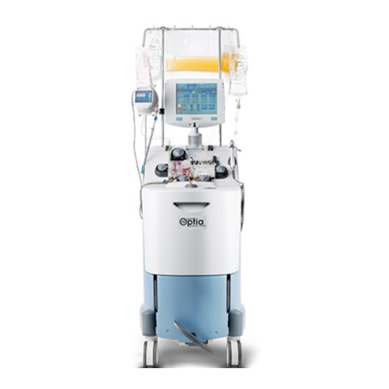
System Components System Components The Spectra Optia system components include the video display, front panel, centrifuge chamber, and electronics compartment. Figure 1-1: Spectra Optia system, front and back views Table 1-1: Spectra Optia System Components Component Function Monitor with touch screen Allows you to communicate with the system. - Page 24 Operational Description Table 1-1: Spectra Optia System Components (continued) Component Function Power switch Allows you to turn power to the system on and off. View port Allows you to look through the centrifuge door to see the interface in the channel.
-
Page 25: Modes Of Operation And Procedure States
Automatic mode. Under those conditions, the interface position does not appear on the screen and you must use the viewport to see the interface. Service Mode Service mode allows technicians to connect to the Spectra Optia system using service software for troubleshooting and maintenance. Procedure States The procedure states listed in the following table describe system activity from the perspective of the operator. - Page 26 System verifies that the lines to the patient are clamped before it raises the cassette. Unload System raises the cassette and unloads the pumps. Procedure summary System displays the final procedure values. Next procedure System prepares for the next procedure. Spectra Optia Apheresis System Service Manual...
-
Page 27: User Interface
User Interface User Interface The Spectra Optia system’s user interface allows you to perform, adjust, and monitor procedures. Navigating the Screen Figure 1-2: Example screen Table 1-3: User Interface elements Section Description Menu bar Contains menu buttons that you touch to show or hide menu tabs. - Page 28 Screen Colors The Spectra Optia system uses a color scheme to indicate the different states and conditions of the procedure, allowing you to quickly determine the progress of the procedure. Table 1-4: Corresponding color schemes for operating states and conditions...
- Page 29 User Interface The buttons and icons described in the following table appear on the monitor or the screens, and either allow you to operate and adjust the Spectra Optia system during an apheresis procedure, or communicate important information. Table 1-6: Button and Icons...
- Page 30 Semi-Automatic mode Bottom right side of the Indicates that the system icon run screens is operating in Semi- Automatic mode. 1-10 Spectra Optia Apheresis System Service Manual...
-
Page 31: Exchange Disposable Tubing Set
10220 0122 Note: The 10200 Exchange set can only be used with TPE procedures. The 10220 Exchange set can be used with both TPE and RBCX procedures. Figure 1-3: The Exchange set (10200) Spectra Optia Apheresis System Service Manual 1-11... - Page 32 Allows AC to be pumped through the tubing but prevents the free flow of AC. Return line Carries blood components from the reservoir to the patient. The luer (male) connects to the patient return access. 1-12 Spectra Optia Apheresis System Service Manual...
- Page 33 Used during centrifugation to separate cellular components from plasma. Connector Holds the lines where the separated components exit the channel. Vent bag Holds air displaced from the system. Remove bag Holds removed blood components. Spectra Optia Apheresis System Service Manual 1-13...
- Page 34 The spikes (white) are used to spike the replacement fluid container. The clamps (white) are used to clamp the replacement line. The luer (male/female) allows connection of a filter or blood warmer tubing. 1-14 Spectra Optia Apheresis System Service Manual...
-
Page 35: Collection Disposable Tubing Set
Diversion bag Used to capture a skin plug after performing a peripheral venipuncture, or to collect a blood sample. Also includes: • Clamp (yellow): Used to clamp the line to the diversion bag. Spectra Optia Apheresis System Service Manual 1-15... - Page 36 Used to hold the fluid that is returned to the patient. Includes a 200- micron filter. Return pressure sensor Attaches to the return pressure sensor on the front panel to monitor diaphragm pressure in the return line. 1-16 Spectra Optia Apheresis System Service Manual...
- Page 37 • Clamp (blue): Used to clamp the plasma line below the plasma bag. Also used to strip the fluid in the plasma line into the plasma bag. Collection bag Holds collected blood components. Spectra Optia Apheresis System Service Manual 1-17...
- Page 38 Sterile barrier filter (0.2 microns): Prevents bacteria from entering the system to maintain a functionally closed system. • Frangible connector: Helps to maintain a functionally closed system. • Clamp (blue): Used to clamp the accessory line. 1-18 Spectra Optia Apheresis System Service Manual...
-
Page 39: Therapeutic Plasma Exchange
The Spectra Optia system cycles through two phases of operation during a TPE procedure, buildup and flush. In the buildup phase, the system adjusts the plasma pump flow rate to maintain the red blood cell (RBC) interface. - Page 40 Operational Description Figure 1-7: Blood component separation in the connector (10200 set) Figure 1-8: TPE flow paths (10220 set) 1-20 Spectra Optia Apheresis System Service Manual...
- Page 41 Therapeutic Plasma Exchange Figure 1-9: Blood component separation in the connector (10220 set) Spectra Optia Apheresis System Service Manual 1-21...
-
Page 42: Mononuclear Cell Collection
The MNC (Mononuclear Cell) protocol is a patient or donor procedure involving the separation and collection MNCs. The Spectra Optia system cycles through three main phases of operation during an MNC collection procedure, the interface establishment phase, the chamber fill phase and the MNC collection phase. - Page 43 Mononuclear Cell Collection Figure 1-11: Blood component separation in the connector Spectra Optia Apheresis System Service Manual 1-23...
-
Page 44: Red Blood Cell Exchange Procedure Types
Operational Description Red Blood Cell Exchange Procedure Types The Spectra Optia system can be used to perform the following types of Red Blood Cell Exchange (RBCX) procedures: • Exchange • Depletion/Exchange • Depletion During an exchange procedure, the system removes defective RBC from the patient and replaces them with healthy donor RBC. - Page 45 Red Blood Cell Exchange Procedure Types Figure 1-13: Blood component separation in the connector Spectra Optia Apheresis System Service Manual 1-25...
-
Page 46: Rbcx Functional Description
RBC to the patient. This phase starts when the centrifuge ramp phase (exchange procedure) or initial depletion procedure (depletion/exchange procedure) is complete and ends when the target FCR (fraction of cells remaining) or target volume of replacement RBC has been attained. 1-26 Spectra Optia Apheresis System Service Manual... -
Page 47: System Description
System Description Spectra Optia Apheresis System Service Manual... - Page 48 System Description System Description The Spectra Optia Apheresis System can be divided into 5 different primary sections: E-box and computer systems, display system, front panel and centrifuge systems, and the AIM system. The front panel system can be sub-divided into pump, valve, sensor, and linear actuator systems.
-
Page 49: E-Box And Computer Systems
5 STC CCA 6 APC CCA 7 Control CCA 8 Control Ethernet CCA 9 Control Computer CCA 10 Centrifuge motor controller 11 64 V switch 12 Power supply Figure 2-1: The Spectra Optia system e-box Spectra Optia Apheresis System Service Manual... - Page 50 System Description Figure 2-2: E-box interconnect diagram Spectra Optia Apheresis System Service Manual...
-
Page 51: Control Cca
Two field-programmable gate arrays (FPGAs) are responsible for communications between the Control computer and sensors. The gate arrays interface to the industry standard architecture (ISA) computer bus. The gate arrays regulate the following control functions of the Control CCA. Spectra Optia Apheresis System Service Manual... - Page 52 The LVDS circuitry multiplexes the 32-TTL (transistor-transistor logic) signals from the Control computer into 8 low-voltage differential lines for signal fidelity. The LVDS signals are converted back to TTL signals on the Display CCA. Spectra Optia Apheresis System Service Manual...
-
Page 53: Control Computer Cca
Ethernet Interface (for external connection to a network) • 32 to 64 Megabyte memory module • Keyboard Interface (connection available on the Control CCA) • IDE disc drive interface • ISA Bus Interface Figure 2-4: The Control Computer CCA Spectra Optia Apheresis System Service Manual... -
Page 54: Control Ethernet Cca
Ethernet cable). The third Ethernet connection is currently not used and must be disabled via a jumper on the outside edge of the CCA. Note: Starting with machine P132, the Safety sub-system Ethernet cable is yellow instead of blue. Figure 2-5: The Control Ethernet CCA Spectra Optia Apheresis System Service Manual... -
Page 55: Other Control Stack Ccas
The Control Port CCA is a pass-through from the Control Interface CCA to the Control Computer CCA. Control Interface CCA The Control Interface CCA houses the hard drive, Power Fail Recovery non-volatile RAM, and acts as a connector converter between the Control CCA to the Control Computer CCA. Spectra Optia Apheresis System Service Manual... - Page 56 System Description Figure 2-7: The Control Interface CCA 2-10 Spectra Optia Apheresis System Service Manual...
-
Page 57: Safety Cca
• Monitors the outputs of the cassette position optical sensors. • Monitors pressing of the Stop or Pause buttons on display module. • Controls 24 V and 64 V switches. Spectra Optia Apheresis System Service Manual 2-11... -
Page 58: Safety Computer Cca
Control computer. The system uses the Versalogic “VS-OptiaS1” safety computer. The Safety computer is an 850 MHz Pentium III processor with built-in 10/100 Ethernet. 2-12 Spectra Optia Apheresis System Service Manual... - Page 59 E-Box and Computer Systems Figure 2-9: The Safety Computer CCA Spectra Optia Apheresis System Service Manual 2-13...
-
Page 60: Other Safety Stack Cca
It communicates through the motherboard to the APC processor via an ISA bus protocol to determine the timing of the camera shutter and the lighting required to acquire images of the interface. 2-14 Spectra Optia Apheresis System Service Manual... - Page 61 STC and FireWire CCAs to communicate with the camera and strobes. The APC CCA contains an off-the-shelf computer product and an interface to the rest of the Spectra Optia system. The APC CCA computer is an Intel Pentium-M processor with a 400 MHz bus. The APC CCA contains an on-board Ethernet port to communicate to the control stack to receive its commands and boot image.
- Page 62 PCI bus on the motherboard. This is the only CCA that uses the PCI bus on the motherboard. FireWire Adapter CCA The FireWire CCA is an adapter CCA from the APC to the camera. 2-16 Spectra Optia Apheresis System Service Manual...
- Page 63 E-Box and Computer Systems Figure 2-13: The FireWire Adapter and FireWire CCAs Spectra Optia Apheresis System Service Manual 2-17...
-
Page 64: Motor Driver Cca
These signals are sent to the Control CCA. Redundant Hall-effect sensors are mounted in the raceway housing of the pump. These signals are monitored by the Safety system to ensure safe limits. 2-18 Spectra Optia Apheresis System Service Manual... - Page 65 ON or OFF with no speed control. Three optical sensors for each valve assembly (all located on the Valve Sensor CCA) sense valve position. The signals are sent back to the Spectra Optia Apheresis System Service Manual 2-19...
- Page 66 Note: Only one valve motor is driven at a time. This includes the linear actuator. Caution: The connectors for the display and valve cables are identical. If these cables are accidentally swapped, electronic components will be damaged. Make sure these cables are plugged into the correct sockets. 2-20 Spectra Optia Apheresis System Service Manual...
- Page 67 E-Box and Computer Systems Figure 2-16: Valve interconnect diagram Spectra Optia Apheresis System Service Manual 2-21...
- Page 68 CCA and Safety system. The sensors are mounted on the frame next to the linear actuator and sense whether the actuator is in the up or down position so that the Control CCA can stop the motor at the appropriate position. 2-22 Spectra Optia Apheresis System Service Manual...
- Page 69 E-Box and Computer Systems Figure 2-17: Linear actuator interconnect diagram Spectra Optia Apheresis System Service Manual 2-23...
- Page 70 24 V solenoid power. The centrifuge door-lock solenoid has its own 24 V power supply on the Motor Driver CCA. The Control system monitors the solenoid position as it attempts to lock the door. It will try five times to lock the door in two-second increments. 2-24 Spectra Optia Apheresis System Service Manual...
- Page 71 E-Box and Computer Systems Figure 2-18: Centrifuge door-lock solenoid interconnect diagram Spectra Optia Apheresis System Service Manual 2-25...
-
Page 72: Display Cca
Driving the audio speaker that warns the operator of alarm/alert conditions. Caution: The connectors for the display and valve cables are identical. If these cables are accidentally swapped, electronic components will be damaged. Make sure these cables are plugged into the correct sockets. 2-26 Spectra Optia Apheresis System Service Manual... - Page 73 E-Box and Computer Systems Figure 2-19: Display CCA interconnect diagram Spectra Optia Apheresis System Service Manual 2-27...
-
Page 74: Top Cap And Motherboard Ccas
The Top Cap CCA also contains minimal front-end analog signal buffering for the ultrasonic circuits (level sensors and fluid detectors). Figure 2-20: Top Cap CCA interconnect diagram 2-28 Spectra Optia Apheresis System Service Manual... -
Page 75: Power System
LEDs on the Motor Driver CCA indicate the status of the 24 V switched and unswitched supplies. If the LEDs are lit, the supplies are within normal range. Spectra Optia Apheresis System Service Manual 2-29... - Page 76 If the LED is lit, the supply is within normal range. If the 5 V DC supply is out of range, a reset signal generates and reboots the Control and Safety Computer CCAs. 2-30 Spectra Optia Apheresis System Service Manual...
- Page 77 E-Box and Computer Systems Figure 2-21: AC Power interconnect diagram Spectra Optia Apheresis System Service Manual 2-31...
-
Page 78: Cooling Fans
System Description Cooling Fans The Spectra Optia system has three 24 V DC cooling fans. Each fan has a Hall sensor that is monitored by the gate arrays on the Control CCA. Figure 2-22: Fan locations Table 2-2: Fan Location and Function... -
Page 79: Display System
The screen is a 10.4-inch diagonal, 800 x 600 SVGA, active thin film transistor (TFT) liquid crystal display (LCD). The display is backlit by a single, field replaceable, cold-cathode fluorescent tube (CCFT) assembly. The CCFT assembly contains two light bulbs. Spectra Optia Apheresis System Service Manual 2-33... - Page 80 Light state Alarm status Safe operating condition. Lights on, flashing Operator-recoverable alert condition, control generated. Lights on, solid Non-recoverable alarm condition, safety generated. The non-recoverable alarm status supersedes the operator- recoverable alert status 2-34 Spectra Optia Apheresis System Service Manual...
-
Page 81: Display Assembly
Warning: High voltage is present in the power inverter card. Arm cable The arm cable carries power, video signals, touch-screen input, and stop and pause button input from the Display CCA to the Control CCA. Spectra Optia Apheresis System Service Manual 2-35... - Page 82 The speaker conveys sound from the amplifier on the Control CCA. Backing plate The backing plate mounts the display assembly on the arm. Note: The Spectra Optia CCFT assembly contains two light bulbs. 2-36 Spectra Optia Apheresis System Service Manual...
- Page 83 Display System Figure 2-25: Display CCA interconnect diagram Spectra Optia Apheresis System Service Manual 2-37...
-
Page 84: Pump System
(monitored by the Safety computer) act as a redundant speed monitor, independent of the encoder monitor circuit (monitored by the Control computer). If the encoder reading and the Hall-effect reading are significantly different, the Spectra Optia system generates a “Hall sensor and encoder in AC pump malfunctioned.” on page 4-189 alarm. - Page 85 The flow rate of the inlet pump is calculated by multiplying the AC pump flow rate by the AC ratio. The maximum speed of the inlet pump is 142 mL/min. Spectra Optia Apheresis System Service Manual 2-39...
- Page 86 The plasma pump controls the level of the interface. The collect/replace pump pumps cells from the centrifuge to the Collect/replace pump collection bag during collect procedures, or pumps replacement solutions from a container to the return reservoir during exchange procedures. 2-40 Spectra Optia Apheresis System Service Manual...
-
Page 87: Pump Assembly
Motor Driver CCA to the pump motor. Hall-effect sensor The Hall-effect sensors act as a redundant speed monitor by reporting the pump speed to the Safety CCA. The sensor is mounted to the pump raceway. Spectra Optia Apheresis System Service Manual 2-41... - Page 88 System Description Figure 2-29: Pump interconnect diagram 2-42 Spectra Optia Apheresis System Service Manual...
-
Page 89: Valve System
If a valve motor fails, replace the entire valve assembly. Note: Only the linear actuator or one valve or motor is driven at a time. 1 RBC/replace valve 2 Plasma valve 3 Remove/collect valve Figure 2-30: Valve locations (front) Spectra Optia Apheresis System Service Manual 2-43... - Page 90 The remove/collect valve directs the flow of plasma to the remove bag or to the return reservoir for exchange procedures. It directs the flow of cells to the collect bag or to the return reservoir for collection procedures. 2-44 Spectra Optia Apheresis System Service Manual...
-
Page 91: Valve Assembly
The Valve Sensor CCA Note: The set ID detector harness passes through the Valve Sensor CCA (valve board). 1 Valve motor 2 Drive terminals 3 Optical encoders 4 Valve Sensor CCA Figure 2-32: Valve components Spectra Optia Apheresis System Service Manual 2-45... - Page 92 Motor Driver CCA to the valve motor Optical encoders The optical encoders report the position of the valves to the Control CCA. Valve Sensor CCA The optical encoders are mounted on the Valve Sensor CCA, 2-46 Spectra Optia Apheresis System Service Manual...
- Page 93 Valve System Figure 2-33: Valve interconnect diagram Spectra Optia Apheresis System Service Manual 2-47...
-
Page 94: Sensor System
Pressure Sensors The pressure sensors (4) measure access, return, centrifuge, and plasma column pressures. 1 RPS 2 IPS 3 CPS 4 PPS Figure 2-34: Pressure sensor locations (front) 2-48 Spectra Optia Apheresis System Service Manual... - Page 95 Collection Configuration Return pressure sensor (RPS) Return pressure sensor (RPS) Inlet pressure sensor (IPS) Inlet pressure sensor (IPS) Centrifuge pressure sensor (CPS) Centrifuge pressure sensor (CPS) Plasma column pressure sensor (PPS) Not used Spectra Optia Apheresis System Service Manual 2-49...
- Page 96 Note: Overly high centrifuge pressures are usually the result of line occlusions or an air block. Plasma column pressure sensor The plasma column pressure sensor (PPS) is for use with future (PPS) releases. 2-50 Spectra Optia Apheresis System Service Manual...
- Page 97 Sensor System Figure 2-36: Pressure sensor interconnect diagram Spectra Optia Apheresis System Service Manual 2-51...
-
Page 98: Reservoir Level Sensors
1 High level 2 Low level Figure 2-37: Reservoir level sensor locations (front) 1 High level 2 Low level Figure 2-38: Reservoir level sensor locations (back) 2-52 Spectra Optia Apheresis System Service Manual... - Page 99 (both sensors see air), and error (high-level sensor sees fluid and low-level sensor sees air). The Safety CCA only monitors the low-level reservoir sensor for air and has two states: empty and mid. Spectra Optia Apheresis System Service Manual 2-53...
- Page 100 System Description Figure 2-39: Reservoir sensor interconnect diagram 2-54 Spectra Optia Apheresis System Service Manual...
-
Page 101: Reservoir Management
2. The return pump stops while the other pumps continue to run at their commanded speeds. 3. The draw cycle continues until the Spectra Optia system calculates that 1.5 mL of fluid have been pumped into the reservoir or 2 seconds after detecting fluid at the low level sensor, which ever is longer. -
Page 102: Fluid Sensors
2-MHz signal and sensor. This sensor is built into a small housing located on the front panel above and on the right side of the cassette. 2-56 Spectra Optia Apheresis System Service Manual... - Page 103 Sensor System Figure 2-41: Sensor interconnect diagram Spectra Optia Apheresis System Service Manual 2-57...
-
Page 104: Return Line Air Detector
Upper User Strobe Driver CCA as a pass-through to the Control CCA. The signal is processed on the USTC FPGA located on the Control CCA. If air is detected, an alarm is generated and the “Air in Return Line” recovery process is started. 2-58 Spectra Optia Apheresis System Service Manual... - Page 105 Sensor System Figure 2-42: Return line air detector interconnect diagram Spectra Optia Apheresis System Service Manual 2-59...
-
Page 106: Set Id Detector
System Description Set ID Detector The set ID detector detects the type of cassette loaded on the Spectra Optia system using a bar code reader. Figure 2-43: Set ID detector location (front) 2-60 Spectra Optia Apheresis System Service Manual... - Page 107 Sensor System Figure 2-44: Set ID detector location (back) Spectra Optia Apheresis System Service Manual 2-61...
- Page 108 System Description Figure 2-45: Set ID detector interconnect diagram Note: The set ID detector harness passes through the Valve Sensor CCA (valve board). 2-62 Spectra Optia Apheresis System Service Manual...
-
Page 109: Rbc Detector
The RBC detector is used to detect RBCs in the plasma line to during exchange procedures. For MNC procedures, it is used as one of the triggers to determine that the chamber is full and that a collection should be started. Figure 2-46: RBC detector location (front) Spectra Optia Apheresis System Service Manual 2-63... - Page 110 System Description Figure 2-47: RBC detector location (back) 2-64 Spectra Optia Apheresis System Service Manual...
- Page 111 Sensor System Figure 2-48: RBC detector interconnect diagram Spectra Optia Apheresis System Service Manual 2-65...
-
Page 112: Fluid Leak Detector
V indicates an open circuit. During startup tests and prior to loading a tubing set, the system checks the ability of the leak detector to operate normally. Figure 2-49: The fluid leak detector 2-66 Spectra Optia Apheresis System Service Manual... - Page 113 Sensor System Figure 2-50: Fluid leak detector interconnect diagram Spectra Optia Apheresis System Service Manual 2-67...
-
Page 114: Linear Actuator System
Note: Only one valve or linear actuator motor is driven at a time. 1 Linear actuator motor 2 Lead screw 3 Slip clutch 4 Optical sensor and sensor flag Figure 2-51: Linear actuator 2-68 Spectra Optia Apheresis System Service Manual... - Page 115 The slip clutch stops the linear actuator in case of a jam or finger entanglement Optical sensor and sensor flag The two optical sensor assemblies detect when the cassette tray is in the up and down positions using the sensor flag. Spectra Optia Apheresis System Service Manual 2-69...
- Page 116 System Description Figure 2-52: Linear actuator interconnect diagram 2-70 Spectra Optia Apheresis System Service Manual...
-
Page 117: Aim System
The trigger harness cable carries timing signals from the STC CCA. On power up, the green LED on the camera remains dim until the setup and communications information has been properly initialized. After initialization, the green LED is brightly illuminated. Spectra Optia Apheresis System Service Manual 2-71... - Page 118 During calibration, the STC commands the camera into Emulation mode. In Emulation mode the shutter's trigger pulses are generated by the STC and the shutter captures a frame every rotation of the filler. 2-72 Spectra Optia Apheresis System Service Manual...
-
Page 119: Lighting System
2 V is measured, then the output is 12 V. In future revisions, the service software will control this calibration. All CCAs include a load-dump field effect transistor that will Spectra Optia Apheresis System Service Manual 2-73... - Page 120 Note: The upper and lower Camera Strobe Driver CCAs are not interchangeable. Caution: Turn the machine power off before removing the Strobe Driver CCA covers. There is a risk of an electrical short when removing the covers. 2-74 Spectra Optia Apheresis System Service Manual...
- Page 121 AIM System Figure 2-55: Upper Camera Strobe Driver CCA Figure 2-56: Lower Camera Strobe Driver CCA Spectra Optia Apheresis System Service Manual 2-75...
- Page 122 System Description Figure 2-57: Camera Strobe Driver CCA locations 2-76 Spectra Optia Apheresis System Service Manual...
- Page 123 The USTC (User Strobe Timing Control) controls the user strobes. The USTC circuitry is located on the Control CCA. Caution: Turn the machine power off before removing the Strobe Driver CCA covers. There is a risk of an electrical short when removing the covers. Spectra Optia Apheresis System Service Manual 2-77...
- Page 124 System Description Figure 2-59: User Strobe Driver CCA (jumper circled) 2-78 Spectra Optia Apheresis System Service Manual...
- Page 125 AIM System Figure 2-60: User Strobe Driver CCA locations Spectra Optia Apheresis System Service Manual 2-79...
- Page 126 System Description Figure 2-61: User strobe interconnect diagram 2-80 Spectra Optia Apheresis System Service Manual...
-
Page 127: Centrifuge System
• The centrifuge contains an open port for loading the disposable channel, which occupies the middle of the gear train hub. Note: The Spectra Optia and Trima Accel centrifuge basins are not interchangeable. Spectra Optia Apheresis System Service Manual 2-81... - Page 128 8 Leak detector 9 Centrifuge arm 10 Lower camera strobe (not visible) 11 Lower bearing holder 12 Filler 13 Centrifuge loading port 14 Lower user strobe (not visible) Figure 2-62: The centrifuge door and basin 2-82 Spectra Optia Apheresis System Service Manual...
- Page 129 The user strobes are controlled by the USTC. The upper bearing holder holds the centrifuge tubing in place at the Upper bearing holder upper end of the centrifuge arm. Spectra Optia Apheresis System Service Manual 2-83...
- Page 130 The upper and lower user strobe assemblies visually freezes the Lower user strobe assembly image of the channel so the operator can observe the separation of blood components in the channel. The user strobes are controlled by the USTC. 2-84 Spectra Optia Apheresis System Service Manual...
-
Page 131: Centrifuge Drive Assembly
The gear assembly allows the filler to spin at the command speed Gear assembly and the centrifuge arm to spin at half the commanded speed. This speed difference, combined with other aspects of the system's design, prevents the centrifuge loop from twisting. Spectra Optia Apheresis System Service Manual 2-85... - Page 132 STC (Synchronization and Timing Control) for camera timing and timing of the camera strobes. • USTC (User Synchronization and Timing Control) for timing of the user strobes. There are 2,048 encoder pulses per revolution. 2-86 Spectra Optia Apheresis System Service Manual...
-
Page 133: Filler Assembly
The chamber bracket holds the collection chamber in place (for Chamber bracket future use). The channel secures the channel and the connector in the filler. Channel The locking pin locks the hex collar in place. Locking pin Spectra Optia Apheresis System Service Manual 2-87... - Page 134 The optical reference is a high-contrast region on the filler that the Optical reference AIM system uses to calculate a reference point when measuring the location of the RBC/buffy coat interface. Figure 2-65: The optical reference 2-88 Spectra Optia Apheresis System Service Manual...
-
Page 135: Centrifuge Motor Controller
If so, a “Centrifuge Hardware Failure” alarm generates. When the centrifuge stops, due to either a command or an alarm condition, the control system and the safety system can command the motor controller to brake the centrifuge motor. Spectra Optia Apheresis System Service Manual 2-89... - Page 136 System Description Figure 2-66: Centrifuge control system interconnect diagram 2-90 Spectra Optia Apheresis System Service Manual...
- Page 137 Centrifuge System Figure 2-67: The centrifuge motor controller Spectra Optia Apheresis System Service Manual 2-91...
-
Page 138: Mechanical System
(viewed from the front) of the machine. A rod with two ball-and-socket joints links the two locking mechanisms. The vertical rod on the right side is not welded to the center horizontal bar, allowing to the dual IV pole to move up and down without binding. 2-92 Spectra Optia Apheresis System Service Manual... - Page 139 Mechanical System Figure 2-68: Dual IV pole Spectra Optia Apheresis System Service Manual 2-93...
- Page 140 System Description 1 Ball-and-socket joints 2 Linking rod 3 Pole shafts Figure 2-69: Dual IV pole locking mechanisms (from the rear of the machine, looking up) 2-94 Spectra Optia Apheresis System Service Manual...
-
Page 141: Wheel And Brake System
Center Allows all four casters to move freely and all wheels rotate freely. Right Locks the front casters and front wheels. The rear casters remain unlocked and rear wheels rotate freely. Spectra Optia Apheresis System Service Manual 2-95... - Page 142 System Description 2-96 Spectra Optia Apheresis System Service Manual...
-
Page 143: Software Description
Software Description Spectra Optia Apheresis System Service Manual... - Page 144 The Spectra Optia software is divided into three layers: Base, Set, and Protocol. The Base layer loads first and includes states and substates common to both set types and all protocols. The Set layer includes states and substates specific to a particular tubing set and the procedures that run on that tubing set.
- Page 145 Software Description Figure 3-2: Typical sequence overview Spectra Optia Apheresis System Service Manual...
-
Page 146: Base Layer Software States
Base Layer Software States The Base layer contains the software states common to all sets and protocols. These are the software states that control the basic functionality of the Spectra Optia system. Power Control State The Power Control state controls the power supplies and switched voltages. It also monitors all DC power supplies. - Page 147 The Power Request Idle substate reports the status of the power supplies to the Control and safety systems, and monitors the systems for power requests. The Power Request Idle substate automatically informs the control system if the Safety system has disabled one of the switched power Spectra Optia Apheresis System Service Manual...
- Page 148 “Safety system did not respond to power If the safety system does not acknowledge within 10 request.” on page 4-483 seconds of the completion of the power test, the control system generates this alarm. Spectra Optia Apheresis System Service Manual...
-
Page 149: Startup State
The startup tests are executed before a disposable tubing set is loaded and before the patient is connected. These tests ensure that the Spectra Optia system is operational, that critical safety features are in place, and that computer redundancy is functioning. During power fail recovery situations only some of tests are performed to insure safety of the already connected patient. - Page 150 “System could not read primary configuration If the main, backup, and default copies of the file.” on page 4-510 configuration files cannot be read, the Spectra Optia system may not work properly—depending on which file failed to load. T1 CPU Check The T1 CPU Check substate checks that the Control Computer processor meets the minimum memory requirements.
- Page 151 Fault Recovery Check System Response The cassette plate is raised. This is a new procedure. The Spectra Optia system proceeds to the T1 Pump Power Test state. The cassette plate is lowered and the non-volatile RAM The procedure was interrupted and must be recovered.
- Page 152 If the safety system fails to respond, the control non-volatile RAM is marked as invalid, and the Spectra Optia system proceeds to the Fault Recovery Alarm substate with Load Protocol substate. The Get Safety NVR Status substate can fail for one of the following reasons: •...
- Page 153 If the Spectra Optia system is recovering from a fault, the information is read from the non- volatile RAM and proceeds according to the information from the Fault Recovery Alarm substate.
-
Page 154: T1 Pump Power Test State
Hall effect sensors, the safety system generates an alarm and waits for the operator to respond. Shutdown Test The Shutdown Test contains 3 functions designed to verify that the pumps do not move before the drivers are loaded. 3-12 Spectra Optia Apheresis System Service Manual... - Page 155 If one or more pumps moves during the test, the control system generates this alarm. Test Done The Test Done substate informs the Spectra Optia system that the T1 Pump Power Test substates are complete. Spectra Optia Apheresis System Service Manual...
-
Page 156: T1 Device Test State
(when viewed form the front of the machine). If any of the valves fails to move the post to the commanded position in 8 seconds, the system generates an alarm and waits for the operator to respond. 3-14 Spectra Optia Apheresis System Service Manual... - Page 157 The Set ID Test substate initializes the Set ID barcode reader. There are no alarms associated with this substate. If the barcode is malfunctioning, the operator is alerted during the disposables set load. Unlock Door The Unlock Door substate unlocks the centrifuge door if it is not already unlocked. Spectra Optia Apheresis System Service Manual 3-15...
-
Page 158: T1 Apc Test State
The ReadStartupTestConfig substate puts the APC in a known starting condition. It clears any previous faults and reset the camera if necessary. APCSystemInfo The APCSystemInfo substate reports the CPU type and memory size of the APC subsystem. 3-16 Spectra Optia Apheresis System Service Manual... - Page 159 If the startup tests take longer than 90 seconds, the test.” on page 4-44 control system generates this alarm. APCStartupTestComplete The APCStartupTestComplete substate notifies the system that the T1 APC Test substates are complete. Spectra Optia Apheresis System Service Manual 3-17...
-
Page 160: T1 Centrifuge Power Test State
If the Spectra Optia system hasn't previously seen the centrifuge basin door opened since it was last booted, the operator is prompted to open and close then door. - Page 161 The Safety Power Test verifies that the centrifuge does not move when the power to the centrifuge is turned off. Shutdown Test The Shutdown Test substate verifies that the centrifuge can be stopped. This substate is divided into three functions. Spectra Optia Apheresis System Service Manual 3-19...
- Page 162 The Unlock Door substate turns the power to the door lock on and commands the door to unlock. Test Done The Test Done substate notifies the system that the T1 Centrifuge Power Test substates are complete. 3-20 Spectra Optia Apheresis System Service Manual...
-
Page 163: Load Disposable State
ID is read. When the cassette has been lowered, the pumps are stopped and the system checks that the pressure sensors have loaded properly. Finally, the set ID is checked. Valves Center The Valves Center substate commands the valves to the center position. Spectra Optia Apheresis System Service Manual 3-21... - Page 164 If the pressure sensor auto-zero reading exceeds the test.” on page 4-433* allowable difference since the previous auto-zero function, the control system generates this alarm. * Where <n> is the pressure sensor number. 3-22 Spectra Optia Apheresis System Service Manual...
- Page 165 * Where <n> is the pressure sensor number. Table 3-20: PressureSensor<n>AutoZeroDiffFailed* limits Pressure Sensor Max Difference (mm Hg) Sensor 1 Sensor 2 Sensor 3 Sensor 4 * Where <n> is the pressure sensor number. Spectra Optia Apheresis System Service Manual 3-23...
- Page 166 Spectra Optia system returns to the Start Pumps substate. This ensures that air is not pulled into the disposable tubing set from the access and return needles. The control system also detects if there is a pressure change on the pressure sensors outside the change filtered out by the driver.
- Page 167 “Tubing set identification error If the read set ID fails, the control system generates this occurred.” on page 4-549 alarm. Complete The Complete substate notifies the Spectra Optia system that the Load Disposable substates are complete. Spectra Optia Apheresis System Service Manual 3-25...
-
Page 168: Rbc Detector Calibration State
The Calibrate substate initializes the RBC detector. The LED drive values and target reflectance range are listed below. Table 3-24: LED drive values (red and green) Minimum Maximum Table 3-25: Target reflectance range Minimum Maximum 1000 1200 3-26 Spectra Optia Apheresis System Service Manual... - Page 169 If the RBC detector drive reflectance values are outside occurred.” on page 4-549 the target reflectance range, the control system generates this alarm. Calibrate Done The Calibrate Done substate notifies the system that the RBC Detector Calibration substates are complete. Spectra Optia Apheresis System Service Manual 3-27...
-
Page 170: Disconnect Test State
Software Description Disconnect Test State The Disconnect Test state ensures that the patient has been disconnected from the Spectra Optia system. The Disconnect Test is performed up to 3 times before unloading the disposable set. The only pumps that are allowed to move during the Disconnect Test state are the return pump (pump 3) and the inlet pump (pump 2). - Page 171 If the safety system fails to send its disconnect test results, the control system automatically counts it as a failure and restarts the test. After the Spectra Optia system is able to reach the target pressure as read by the return or inlet pressure sensor, it will dwell for 5 seconds.
-
Page 172: Unload Disposable State
The Unload Disposable state is responsible for prompting the operator to perform the disconnect test and unload the tubing kit. Note: The Disconnect Test state is not contained within the Unload Disposable state. Figure 3-17: The Unload Disposable state sequence 3-30 Spectra Optia Apheresis System Service Manual... - Page 173 Stop Pumps The Stop Pumps substate stops the pumps and transitions to the Complete substate. Complete The Complete substate notifies the system that the Unload Disposable substates are complete. Spectra Optia Apheresis System Service Manual 3-31...
-
Page 174: Set Layer Software States
Set Layer Software States The Set layer contains the software states specific to either the exchange or collection set. These are the software states that control the functionality of the Spectra Optia system with respect to the type of set loaded. - Page 175 The Test Disposable substates test the disposable tubing set for leaks. Before performing the tests, the Spectra Optia system verifies the correct disposable tubing set is loaded, checks for power fail recovery, and prompts the operator to close the saline, inlet, and return lines. Then simultaneous inlet and return pressure tests are performed.
- Page 176 This operator attention alarm prompts the operator to close the inlet and return lines for the pressure test to begin. InletPos The InletPos substate pressurizes the inlet pressure sensor to the alarm limit of 400 mmHg. 3-34 Spectra Optia Apheresis System Service Manual...
- Page 177 5 seconds, this alarm is generated by the control system. InletReturn The InletReturn substate starts the simultaneous inlet and return pressure tests. InletNeg The InletNeg substate pressurizes the inlet pressure sensor to the negative alarm limit of –350 mmHg. Spectra Optia Apheresis System Service Manual 3-35...
- Page 178 5 seconds, this alarm is generated by the control system. InletPostTest The InletPostTest substate returns the pressure to 0 mmHg. Table 3-41: InletPostTest substate Pump Commanded Speed (mL/min) Pump 1 Pump 2 3-36 Spectra Optia Apheresis System Service Manual...
- Page 179 The ReturnPos substate pressurizes the return pressure sensor to the alarm limit of 400 mmHg. Table 3-43: ReturnPos substate Pump Commanded Speed (mL/min) Pump 1 Pump 2 Pump 3 Pump 4 Pump 5 *The return pressure tests do not command the inlet or AC pumps. Spectra Optia Apheresis System Service Manual 3-37...
- Page 180 350 mmHg. Table 3-46: ReturnNeg substate Pump Commanded Speed (mL/min) Pump 1 Pump 2 Pump 3 -160 Pump 4 Pump 5 *The return pressure tests do not command the inlet or AC pumps. 3-38 Spectra Optia Apheresis System Service Manual...
- Page 181 The ReturnPostTest substate returns the pressure on the return pressure sensor to 0 mmHg. Table 3-49: ReturnPostTest substate Pump Commanded Speed (mL/min) Pump 1 Pump 2 Pump 3 Pump 4 Pump 5 *The return pressure tests do not command the inlet or AC pumps. Spectra Optia Apheresis System Service Manual 3-39...
- Page 182 0 mmHg after 22.3 mL has been pumped by the return pump, this alarm is generated by the control system. Complete The Complete substate informs the Spectra Optia system that the Test Disposables state is complete. 3-40 Spectra Optia Apheresis System Service Manual...
- Page 183 Set Layer Software States Prime Disposable State The Prime Disposable state primes the disposable set with saline, tests the sensors, and the tests the channel for leaks. Figure 3-19: The Prime Disposable State Sequence Spectra Optia Apheresis System Service Manual 3-41...
- Page 184 In the event of a power failure during the priming of the disposable tubing set, the Spectra Optia system stores data to the power fail non-volatile RAM to properly recover when power is restored.
- Page 185 The PrimeReturnLine substate checks the saline line for an open clamp and primes the return line. The inlet pressure sensor is used to determine if the saline line is occluded, and automatically performs a check if the pressure drops by more than 100 mmHg. Spectra Optia Apheresis System Service Manual 3-43...
- Page 186 The recirculation and plasma lines are primed with saline. Table 3-58: PrimeInletLine substate Pump Commanded Speed (mL/min) Pump 1 Pump 2 3-44 Spectra Optia Apheresis System Service Manual...
- Page 187 “Inlet saline line was obstructed.” on page 4-245 If the inlet pressure sensor reading is greater than 440 mmHg or less than –390 mmHg, this alarm is generated by the control system. The Spectra Optia system automatically continues if the pressure reduces by half.
- Page 188 CentrifugeRampUp The CentrifugeRampUp substate of the PrimeChannel substate ramps up the centrifuge to 3,000 rpm to remove air from the channel. The Spectra Optia system ensures that the door is closed and locked before commanding the centrifuge to run. 3-46...
- Page 189 If the centrifuge pressure sensor reports a reading malfunctioned.” on page 4-123 less than 30 mmHg, this alarm is generated by the control system. Complete The Complete substate informs the Spectra Optia system that the Prime Disposable state is complete. Spectra Optia Apheresis System Service Manual 3-47...
- Page 190 The Post Startup Tests State performs tests during the CentrifugeDwell substate of the Prime Disposable state. The tests verify that the camera is able to lock onto the optical reference point when the Spectra Optia system is running a procedure. Figure 3-20: The Post Startup Tests state sequence...
- Page 191 The LightingCalibration substate performs the lighting calibration by verifying that it is able to see the correct image from the ConnectorSearch substate. It then calibrates the lighting by adjusting the intensity and duration of strobe flashes. Spectra Optia Apheresis System Service Manual 3-49...
- Page 192 Custom Prime State After the Spectra Optia system has been primed with saline, the Custom Prime state allows the flexibility to perform a blood prime if needed. A blood prime is usually performed when the patient’s TBV or hematocrit is very low, however, it can be performed under other circumstances as well. In order to perform a custom prime, the operator must enter the hematocrit (if RBCs are being used) and volume of the blood bag they are using to prime the system.
- Page 193 The PromptCloseInlet substate prompts the operator to close the inlet line from the patient. Table 3-67: PromptCloseInlet alarm Alarm Details “Clamp inlet line.” on page 4-143 This operator attention alarm prompts the operator to close the inlet line. Spectra Optia Apheresis System Service Manual 3-51...
- Page 194 The ChannelEvac substate evacuates fluid from the channel by using the plasma pump to draw as much fluid as possible from the channel and return it to the patient. Centrifuge commanded speed: 0 rpm 3-52 Spectra Optia Apheresis System Service Manual...
- Page 195 If the inlet pressure sensor reading is below -200 rinseback.” on page 4-247 mmHg, this alarm is generated by the control system. Complete The Complete substate informs the Spectra Optia system that the Rinseback state is complete. Spectra Optia Apheresis System Service Manual 3-53...
-
Page 196: Exchange States
The Test Disposable state tests the disposable tubing set for leaks critical to the patient. The inlet and return lines are checked for occlusion and leaks. At the end of the Test Disposable state, the system evacuates the air from the bags. Figure 3-22: The Test Disposable state sequence 3-54 Spectra Optia Apheresis System Service Manual... - Page 197 The Test Disposable substates test the disposable tubing set for leaks. Before performing the tests, the Spectra Optia system verifies the correct disposable tubing set is loaded, checks for power fail recovery, and prompts the operator to close the saline, inlet, and return lines. Then simultaneous inlet and return pressure tests are performed.
- Page 198 This operator attention alarm prompts the operator to close the inlet and return lines for the pressure test to begin. InletPos The InletPos substate pressurizes the inlet pressure sensor to the alarm limit of 400 mmHg. 3-56 Spectra Optia Apheresis System Service Manual...
- Page 199 5 seconds, this alarm is generated by the control system. InletReturn The InletReturn substate starts the simultaneous inlet and return pressure tests. InletNeg The InletNeg substate pressurizes the inlet pressure sensor to the negative alarm limit of –350 mmHg. Spectra Optia Apheresis System Service Manual 3-57...
- Page 200 5 seconds, this alarm is generated by the control system. InletPostTest The InletPostTest substate returns the pressure to 0 mmHg. Table 3-87: InletPostTest substate Pump Commanded Speed (mL/min) Pump 1 Pump 2 3-58 Spectra Optia Apheresis System Service Manual...
- Page 201 The ReturnPos substate pressurizes the return pressure sensor to the alarm limit of 400 mmHg. Table 3-89: ReturnPos substate Pump Commanded Speed (mL/min) Pump 1 Pump 2 Pump 3 Pump 4 Pump 5 *The return pressure tests do not command the inlet or AC pumps. Spectra Optia Apheresis System Service Manual 3-59...
- Page 202 350 mmHg. Table 3-92: ReturnNeg substate Pump Commanded Speed (mL/min) Pump 1 Pump 2 Pump 3 -160 Pump 4 Pump 5 *The return pressure tests do not command the inlet or AC pumps. 3-60 Spectra Optia Apheresis System Service Manual...
- Page 203 The ReturnPostTest substate returns the pressure on the return pressure sensor to 0 mmHg. Table 3-95: ReturnPostTest substate Pump Commanded Speed (mL/min) Pump 1 Pump 2 Pump 3 Pump 4 Pump 5 *The return pressure tests do not command the inlet or AC pumps. Spectra Optia Apheresis System Service Manual 3-61...
- Page 204 0 mmHg after 22.3 mL has been pumped by the return pump, this alarm is generated by the control system. Complete The Complete substate informs the Spectra Optia system that the Test Disposables state is complete. 3-62 Spectra Optia Apheresis System Service Manual...
- Page 205 In the event of a power failure during the priming of the disposable tubing set, the Spectra Optia system stores data to the power fail non-volatile RAM to properly recover when power is restored.
- Page 206 AC ultrasonic fluid detector to ensure that it is able to distinguish air and fluid. Table 3-99: PrimeACLine substate Pump Commanded Speed (mL/min) Pump 1 Pump 2 Pump 3 Pump 4 Pump 5 3-64 Spectra Optia Apheresis System Service Manual...
- Page 207 The inlet pressure sensor is used to determine if the saline line is occluded, and automatically performs a check if the pressure drops by more than 100 mmHg. Table 3-102: PrimeReturnLine substate Pump Commanded Speed (mL/min) Pump 1 Pump 2 Pump 3 -160 Pump 4 Pump 5 Spectra Optia Apheresis System Service Manual 3-65...
- Page 208 Pump 5 Table 3-105: RBC recirculate line prime Valve Commanded Position Valve 1 Return Valve 2 Collect Valve 3 Return Note: Plasma recirculate line prime only applies to the 10200 disposable tubing set. 3-66 Spectra Optia Apheresis System Service Manual...
- Page 209 “Inlet saline line was obstructed.” on page 4-245 If the inlet pressure sensor reading is greater than 440 mmHg or less than –390 mmHg, this alarm is generated by the control system. The Spectra Optia system automatically continues if the pressure reduces by half.
- Page 210 CentrifugeRampUp The CentrifugeRampUp substate of the PrimeChannel substate ramps up the centrifuge to 3,000 rpm to remove air from the channel. The Spectra Optia system ensures that the door is closed and locked before commanding the centrifuge to run. 3-68...
- Page 211 If the centrifuge pressure sensor reports a reading malfunctioned.” on page 4-123 less than 30 mmHg, this alarm is generated by the control system. Complete The Complete substate informs the Spectra Optia system that the Prime Disposable state is complete. Spectra Optia Apheresis System Service Manual 3-69...
- Page 212 The Post Startup Tests State performs tests during the CentrifugeDwell substate of the Prime Disposable state. The tests verify that the camera is able to lock onto the optical reference point when the Spectra Optia system is running a procedure. Figure 3-24: The Post Startup Tests state sequence...
- Page 213 The LightingCalibration substate performs the lighting calibration by verifying that it is able to see the correct image from the ConnectorSearch substate. It then calibrates the lighting by adjusting the intensity and duration of strobe flashes. Spectra Optia Apheresis System Service Manual 3-71...
- Page 214 PostStartupTestComplete The PostStartupTestComplete substate informs the Spectra Optia system that the Post Startup Tests state is complete. 3-72 Spectra Optia Apheresis System Service Manual...
- Page 215 Set Layer Software States Custom Prime State After the Spectra Optia system has been primed with saline, the Custom Prime state allows the flexibility to perform a blood prime if needed. A blood prime is usually performed when the patient’s TBV or hematocrit is very low, however, it can be performed under other circumstances as well.
- Page 216 Since the inlet line is no longer drawing fluid from the patient, the inlet pressure alarms are disabled. The Spectra Optia system will generate an alarm if the return pressure is detected to be above 400 mmHg. The Rinseback state will perform the ChannelEvac and RinseChannel substates three times then a final ChannelEvac.
- Page 217 The ChannelEvac substate evacuates fluid from the channel by using the plasma pump to draw as much fluid as possible from the channel and return it to the patient. Centrifuge commanded speed: 0 rpm Spectra Optia Apheresis System Service Manual 3-75...
- Page 218 If the inlet pressure sensor reading is below -200 rinseback.” on page 4-247 mmHg, this alarm is generated by the control system. Complete The Complete substate informs the Spectra Optia system that the Rinseback state is complete. 3-76 Spectra Optia Apheresis System Service Manual...
-
Page 219: Protocol Layer Software States
Protocol Layer Software States The Protocol layer contains the software states specific to a certain protocol. These are the software states that control the functionality of the Spectra Optia system with respect to the procedure being performed. MNC Run State The MNC Run state controls the functions of the MNC procedure. - Page 220 MNC Run Substates The MNC Run substates begin by diverting prime solution and flushing saline from the centrifuge channel. After the prime is displaced, the initial interface is set up. Then the Spectra Optia system performs the MNC collection. PrimeDivert The PrimeDivert substate sends the saline prime to the saline bag.
- Page 221 10 mL has been pumped by the inlet pump. The APC is disabled during this substate. Table 3-128: PatientPrime substate Valve Commanded Position Valve 1 (Replace) Plasma Valve 2 (Plasma) Return Valve 3 (Collect) Return Spectra Optia Apheresis System Service Manual 3-79...
- Page 222 The FlushChamber substate pumps plasma through the collection chamber to flush some of the platelets from the collection chamber before advancing to the CollectMNC substate to collect the product. The collect pump flow rate is ramped up to the target collect flow rate at this point. 3-80 Spectra Optia Apheresis System Service Manual...
- Page 223 TargetsAttained The Complete substate stops the pumps and centrifuge and waits for the operator to either change the run targets or indicate that the run is complete. Spectra Optia Apheresis System Service Manual 3-81...
-
Page 224: Rbcx Run State
Software Description RBCX Run State The RBCX Run state controls the functions of the RBCX procedure. Figure 3-27: The RBCX Run state sequence 3-82 Spectra Optia Apheresis System Service Manual... - Page 225 Prime Disposable state with patient blood. After the prime is displaced, the interface is algorithmically controlled based patient hematocrit. (The AIM system is used only for spillover monitoring.) Then the Spectra Optia system performs the red blood cell exchange and/or depletion. RunRecoveryCheck The RunRecoveryCheck substate detects if the current run is a reset recovery.
- Page 226 The InterfaceSetup substate sets up the interface based patient hematocrit. The interface setup requires at least 20 mL be pumped by the inlet pump and at least 10 mL be pumped by the plasma pump in order to progress to the next commanded state. 3-84 Spectra Optia Apheresis System Service Manual...
- Page 227 (plasma, custom fluid, or saline/ albumin). The Spectra Optia can perform both a Depletion and Exchange procedure as desired. The Deplete substate stops when the depletion target has been attained, if the centrifuge stops, or if the interface is lost.
- Page 228 Exchange substate after the interface control has been reestablished. Figure 3-29: Exchange substate sequence Table 3-139: Exchange substate Valve Commanded Position Valve 1 (RBC) Collect Valve 2 (Plasma) Collect Valve 3 (Remove) Return 3-86 Spectra Optia Apheresis System Service Manual...
- Page 229 Rinseback state (if applicable). Note: By default, Rinseback is disabled for RBCX. Note: Rinseback is not available if less than 20 mL of fluid has been pumped from the patient to the disposable. Spectra Optia Apheresis System Service Manual 3-87...
-
Page 230: Tpe Run State
The TPE Run substates begin by replacing the saline (or blood component from a custom prime) used in the Prime Disposable state with patient blood. After the prime is displaced, the interface is set up based on information from the APC (AIM system). Then the Spectra Optia system performs the plasma exchange. - Page 231 If the replace fluid sensor detects air after 6 mL has been pumped by the replace pump, the control system generates this alarm. Note: This alarm will also occur during the run if the replace fluid sensor detects air. Spectra Optia Apheresis System Service Manual 3-89...
- Page 232 10 mL be pumped by the plasma pump in order to progress to the next commanded state. Table 3-146: InterfaceSetup substate Valve Commanded Position Valve 1 (RBC) Return Valve 2 (Plasma) Collect Valve 3 (Remove) Return 3-90 Spectra Optia Apheresis System Service Manual...
- Page 233 APC (AIM system) and commands the plasma pump to run accordingly. From this substate, the system either reestablishes the interface with the InterfaceSetup substate, advances to the Flush substate, or advances to the TargetsAttained substate. Spectra Optia Apheresis System Service Manual 3-91...
- Page 234 The Flush substate flushes the channel and returns the buffy coat to the patient. The plasma pump and the replace pump are commanded to the same speed and controlled by the plasma pump algorithm. From this substate, the system either returns to the Exchange substate or advances to TargetsAttained. 3-92 Spectra Optia Apheresis System Service Manual...
- Page 235 The complete substate informs the system that the Run state is complete and advances to the Rinseback state (if applicable). Note: Rinseback is not available if less than 20 mL of fluid has been pumped from the patient to the disposable. Spectra Optia Apheresis System Service Manual 3-93...
- Page 236 Software Description 3-94 Spectra Optia Apheresis System Service Manual...
-
Page 237: Troubleshooting
Troubleshooting Spectra Optia Apheresis System Service Manual... -
Page 238: Non-Alarm Troubleshooting
2. Unplug the blue 4 wire touchscreen connector from the IV pole-side of the display. Figure 4-1: Touchscreen connector (circled) 3. Access the test points for a DVM. On some touchscreens, this requires the connector to be flipped over. Be careful not to bend the harness. Spectra Optia Apheresis System Service Manual... -
Page 239: General Aim Troubleshooting
Post Startup test with the image viewer open. It may also be necessary to cycle power to the system and/or reboot the laptop/service computer. 1. Start the Spectra Optia system in Service mode. 2. Connect to the Spectra Optia system using STS. - Page 240 3. If the image for the optical reference becomes “jittery,” then this is an indication that the coupling between the centrifuge motor and the gear train may be damaged. Spectra Optia Apheresis System Service Manual...
-
Page 241: Troubleshooting Failures During Start Up
Note: It is possible to reset the APC stack BIOS by connecting a computer keyboard and video monitor to the APC stack. This may not be practical in the field. 6. Replace the APC stack if there is no way to reset the BIOS. Spectra Optia Apheresis System Service Manual... - Page 242 BIOS test fails during boot. The Control computer tests its BIOS when the Spectra Optia is turned on. When the BIOS test is complete, the Control stack emits a beep. If the BIOS test fails, the system displays a BIOS error on a black screen.
-
Page 243: Datalog Files
CRC, and directory structure), dlog version, and platform (device type). Each event is recorded on a new line, beginning with a timestamp in YYMMDD_HH:MM:SS format. Column headings, starting near the top of the file, describe event values. For more information about dlog files, refer to the technical training materials. Spectra Optia Apheresis System Service Manual... -
Page 244: Alarm Troubleshooting
Troubleshooting Alarm Troubleshooting The Spectra Optia system has independent Control and Safety systems that constantly monitor the performance of the system. If either the Control or Safety system detects an operation error or potentially unsafe operating condition, the system sounds an alarm, illuminates the warning lights on the front panel, and displays alarm information and troubleshooting instructions on the screen. - Page 245 The alarms are listed alphabetically by the alarm name. To find an alarm, you can scroll through the list or use the search function. Each alarm topic includes information about the alarm, any operator troubleshooting information provided by the Spectra Optia system at the time of the alarm, and any applicable troubleshooting information for service technicians.
- Page 246 Figure 4-5: DLog file with alarm enum highlighted Operator Prompts Operator prompts are on-screen instructions for the operator. The Spectra Optia system records operator prompts in the DLog file using an alarm enum to identify them. Figure 4-6: Example operator prompt...
-
Page 247: Spectra Optia Alarms
Spectra Optia Alarms Spectra Optia Alarms TPE, RBCX, and MNC protocols. Version 5 software. Spectra Optia Apheresis System Service Manual 4-11... -
Page 248: Ac Fluid Detector Detected Fluid Too Soon
Alarm Identification FluidDetector1TooEarly Base Layer System Control Protocol Alarm Name AC fluid detector detected fluid too soon. Alarm Explanation AC fluid detector detected fluid in tubing set when set should have been dry. 4-12 Spectra Optia Apheresis System Service Manual... - Page 249 Operator spiked the bag too early. • Defective fluid sensor. • Defective Top Cap CCA. Suggested Actions • Test the fluid sensor. • Replace the fluid sensor. • Replace the Top Cap CCA. Spectra Optia Apheresis System Service Manual 4-13...
-
Page 250: Ac Fluid Detector Did Not Detect Fluid
1. If the AC line contains fluid, touch Unload to raise the cassette. 2. Contact your service representative for assistance before you begin a new procedure. Table 4-6: Alarm Information Alarm Identification ACDetectionCheckFailed Layer Protocol 4-14 Spectra Optia Apheresis System Service Manual... - Page 251 Suggested Actions • Test the AC fluid sensor. • Replace the AC fluid sensor. • Verify the AC pump motor is working properly. • Replace the AC pump motor. • Replace Top Cap CCA. Spectra Optia Apheresis System Service Manual 4-15...
-
Page 252: Ac Infusion Data Was Invalid
AC pump is moving too fast. • Return pump is moving too fast. • Defective safety stack. Suggested Actions • Test the pumps. • Replace the pump motors or rotors. • Replace the safety stack. 4-16 Spectra Optia Apheresis System Service Manual... -
Page 253: Ac Infusion Data Was Invalid
AC pump is moving too fast. • Return pump is moving too fast. • Defective safety stack. Suggested Actions • Test the pumps. • Replace the pump motors or rotors. • Replace the safety stack. Spectra Optia Apheresis System Service Manual 4-17... -
Page 254: Ac Occlusion Test Failed
2. If the alarm persists, touch Unload and unload the tubing set. 3. Load a new tubing set and resume the procedure. System malfunctioned. Contact your service representative for assistance. Table 4-15: Alarm Information Alarm Identification ACOcclusionCheckFailed Layer Protocol Control System 4-18 Spectra Optia Apheresis System Service Manual... - Page 255 Defective AC pump occlusion. Suggested Actions • Perform the pump occlusion test. • Verify the calibration of the inlet pressure sensor. • Replace the AC pump rotor. • Replace the inlet pressure sensor. Spectra Optia Apheresis System Service Manual 4-19...
-
Page 256: Ac Pump Did Not Stop When Commanded
Alarm Name AC pump did not stop when commanded. Alarm Explanation AC pump did not stop when it should have. If pumps do not stop within 15 seconds, turn off system and disconnect patient. 4-20 Spectra Optia Apheresis System Service Manual... - Page 257 Defective pump motor. • Defective Motor Driver CCA. • Defective control stack. Suggested Actions • Test the pump. • Replace the pump motor. • Replace the Motor Driver CCA. • Replace the control stack. Spectra Optia Apheresis System Service Manual 4-21...
-
Page 258: Ac Pump Malfunctioned
2. Contact your service representative for assistance. Table 4-21: Alarm Information Alarm Identification Pump1ControlFault Layer Base Control System Protocol Alarm Name AC pump malfunctioned. Alarm Explanation AC pump did not operate at commanded flow rate. 4-22 Spectra Optia Apheresis System Service Manual... - Page 259 Defective pump motor. • Defective Motor Driver CCA. • Defective control stack. Suggested Actions • Test the pump. • Replace the pump motor. • Replace the Motor Driver CCA. • Replace the control stack. Spectra Optia Apheresis System Service Manual 4-23...
-
Page 260: Ac Pump Software Error Occurred
Table 4-25: Service Troubleshooting Occurs During Continuously Detection The pump was commanded to an invalid speed. Possible Causes • Defective system software. Suggested Actions • Reinstall the software to the system. • Replace the hard drive. 4-24 Spectra Optia Apheresis System Service Manual... -
Page 261: Ac Pump Speed Was Too High
Replace the AC pump Hall effect connector with the inlet pump Hall effect connector to determine if the Hall effect sensor is faulty. • Replace the AC pump motor. • Replace the Motor Driver CCA. • Replace the safety stack. Spectra Optia Apheresis System Service Manual 4-25... -
Page 262: Ac Pump Turned Faster Than Inlet Pump
2. Contact your service representative for assistance before you begin a new procedure. Table 4-30: Alarm Information Alarm Identification ACDirectlyToPatient Layer System Safety Protocol AC pump turned faster than inlet pump. Alarm Name Alarm Explanation System may have delivered AC too quickly. 4-26 Spectra Optia Apheresis System Service Manual... - Page 263 Inlet pump is moving too slow. • Defective safety stack. Suggested Actions • Test the pumps. • Replace the pump motors or rotors. • Replace the Motor Driver CCA. • Replace the safety stack. Spectra Optia Apheresis System Service Manual 4-27...
-
Page 264: Ac Volume Limit Was Exceeded
Defective Top Cap CCA. Suggested Actions • Test the AC fluid sensor. • Replace the AC fluid sensor. • Verify the AC pump motor is working properly. • Replace the AC pump motor. 4-28 Spectra Optia Apheresis System Service Manual... -
Page 265: Ac Was Not Detected
• Touch Rinseback. • If Rinseback is not an option, touch Disconnect. 2. Contact your service representative for assistance before you begin a new procedure. Table 4-36: Alarm Information Alarm Identification OutOfAC Layer Protocol Spectra Optia Apheresis System Service Manual 4-29... - Page 266 Air is detected at the AC fluid sensor. Possible Causes • Out of AC. • Defective AC fluid sensor. Suggested Actions • Test the AC fluid sensor. • Replace the AC fluid sensor. 4-30 Spectra Optia Apheresis System Service Manual...
-
Page 267: Aim Subsystem Failed
2. Contact your service representative for assistance before you begin a new procedure. Table 4-39: Alarm Information Alarm Identification APCBootFailed Layer Base System Control Protocol AIM subsystem failed. Alarm Name Alarm Explanation AIM system did not function correctly. Spectra Optia Apheresis System Service Manual 4-31... - Page 268 0 Vdc and 5 Vdc. • Remove the STC and FireWire CCAs to see if APC will boot completely. Plug one back in and repeat the test. Replace the applicable component. • Replace the APC stack. 4-32 Spectra Optia Apheresis System Service Manual...
-
Page 269: Aim System's Interface Measurement Data Was Not Updated
Table 4-42: Alarm Information Alarm Identification APCSoftwareWatchdogFault Layer Protocol Control System Protocol Alarm Name AIM system's interface measurement data was not updated. Alarm Explanation AIM system's data was not updated in time allowed. Spectra Optia Apheresis System Service Manual 4-33... - Page 270 Possible Causes • Defective Ethernet cable between control and APC. • Defective APC component. Suggested Actions • Check the Ethernet connection between control and APC. • Replace the APC. 4-34 Spectra Optia Apheresis System Service Manual...
-
Page 271: Aim System Could Not Establish Target Interface
B. Ensure that the lines are correctly loaded and are not obstructed. 4. Close the centrifuge door. 5. Touch Retry. The system automatically clears the lines of air when the centrifuge restarts. Table 4-45: Alarm Information Alarm Identification APCHematocritLimited Layer Protocol System Control Spectra Optia Apheresis System Service Manual 4-35... - Page 272 Operators may decrease the hematocrit to compensate. Possible Causes • Operator alert - incorrect hematocrit entered. • Defective pump 2 occlusion. Suggested Actions • Test pump 2 occlusion. • Replace the pump 2 rotor. 4-36 Spectra Optia Apheresis System Service Manual...
-
Page 273: Aim System Detected Rbc Interface Near Top Of Channel
Spectra Optia Alarms AIM system detected RBC interface near top of channel. RBC interface was higher than expected. Machine Start-up Tests Patient Not Connected Patient Connected Patient Disconnected Spectra Optia Apheresis System Service Manual 4-37... - Page 274 1. Disable the AIM system and resume the procedure, or discontinue the procedure: A. To disable the AIM system, touch Disable. B. To discontinue the procedure, touch Rinseback. C. If Rinseback is not an option, touch Disconnect. 2. Contact your service representative for assistance. 4-38 Spectra Optia Apheresis System Service Manual...
- Page 275 Clean debris off of the camera strobe lenses. • Perform the Top Light Calibration test in the service software. • Perform Startup and Post Startup Tests. • Replace the APC stack. • Replace the camera strobe ssemblies as applicable. Spectra Optia Apheresis System Service Manual 4-39...
-
Page 276: Aim System Did Not Complete Calibration Test
Table 4-51: Alarm Information Alarm Identification APCCalibrateTimeout Layer Protocol Control System Protocol TPE, MNC Alarm Name AIM system did not complete calibration test. Alarm Explanation AIM system did not respond to calibration command. 4-40 Spectra Optia Apheresis System Service Manual... - Page 277 Debris on the glass. • Centrifuge arm in the way of the camera. • Defective APC component. Suggested Actions • Clean the glass port for the camera. • Recalibrate the camera. • Replace the camera. Spectra Optia Apheresis System Service Manual 4-41...
-
Page 278: Aim System Did Not Complete Channel Imaging Test
Table 4-54: Alarm Information Alarm Identification APCPostStartupTestTimeout Layer Protocol Control System Protocol Alarm Name AIM system did not complete channel imaging test. Alarm Explanation AIM system did not respond to command to locate channel detector. 4-42 Spectra Optia Apheresis System Service Manual... - Page 279 Prime Disposable state Occurs During Detection The APC does not report the result of the post startup tests in 60 seconds. Possible Causes • Defective harness. • Defective APC. Suggested Actions • Replace the APC. Spectra Optia Apheresis System Service Manual 4-43...
-
Page 280: Aim System Did Not Complete Illumination Test
2. Touch Retry. Table 4-57: Alarm Information Alarm Identification APCStartupTestTimeout Base Layer System Control Protocol Alarm Name AIM system did not complete illumination test. Alarm Explanation AIM system did not complete illumination test. 4-44 Spectra Optia Apheresis System Service Manual... - Page 281 Suggested Actions • Test the Ethernet cable connection between Control and APC. • Connect with the service software and see if communication to the STC and camera is possible. • Replace the APC stack. Spectra Optia Apheresis System Service Manual 4-45...
-
Page 282: Aim System Did Not Complete Interface Measurement
Table 4-60: Alarm Information Alarm Identification APCMeasureTimeout Layer Protocol Control System Protocol Alarm Name AIM system did not complete interface measurement. Alarm Explanation AIM system did not respond to command to measure interface. 4-46 Spectra Optia Apheresis System Service Manual... - Page 283 Prime Disposable state Occurs During Detection The APC does not report the measurement within 60 seconds of the request. Possible Causes • Defective harness. • Defective APC. Suggested Actions • Replace the APC. Spectra Optia Apheresis System Service Manual 4-47...
-
Page 284: Aim System Did Not Detect Interface
AIM system did not detect interface. AIM system did not detect interface in channel. Look through viewport to see if interface is present. Machine Start-up Tests Patient Not Connected Patient Connected Patient Disconnected 4-48 Spectra Optia Apheresis System Service Manual... - Page 285 3. If the alarm recurs, decrease the entered hematocrit by 3 percentage points again. You may decrease the hematocrit by 3 percentage points up to three times for a maximum decrease of 9 percentage points. Table 4-63: Alarm Information Alarm Identification APCControlNoInterfaceData Layer Protocol Spectra Optia Apheresis System Service Manual 4-49...
- Page 286 Debris on glass. • Defective AIM system component. Suggested Actions • Clean the window and replace as necessary. • Test the camera strobe system and replace drive assemblies as necessary. • Replace the APC CCA. 4-50 Spectra Optia Apheresis System Service Manual...
-
Page 287: Aim System Did Not Respond To System Command
• If the patient is connected and Rinseback is not an option, touch Disconnect. 2. Contact your service representative for assistance before you begin a new procedure. Table 4-66: Alarm Information Alarm Identification APCReadyTimeout Layer Base System Control Spectra Optia Apheresis System Service Manual 4-51... - Page 288 The APC does not respond with a ready state within 60 seconds. Detection Possible Causes • Defective harness. • Defective APC. • Defective control stack. Suggested Actions • Replace the APC. • Replace the control stack. 4-52 Spectra Optia Apheresis System Service Manual...
-
Page 289: Aim System Failed Calibration Test
Automatic mode. Refer to the operator's manual for instructions on using Semi-Automatic mode. 2. Contact your service representative for assistance before you begin a new procedure. Table 4-69: Alarm Information Alarm Identification APCCalibrateFailed Layer Protocol Spectra Optia Apheresis System Service Manual 4-53... - Page 290 Debris on the glass. • Centrifuge arm in the way of the camera. • Defective APC component. Suggested Actions • Clean the glass port for the camera. • Recalibrate the camera. • Replace the camera. 4-54 Spectra Optia Apheresis System Service Manual...
-
Page 291: Aim System Failed Channel Imaging Test
Spectra Optia Alarms AIM system failed channel imaging test. AIM system failed channel imaging test. Machine Start-up Tests Patient Not Connected Patient Connected Patient Disconnected Spectra Optia Apheresis System Service Manual 4-55... - Page 292 3. Re-insert the connector in the filler, and confirm that the channel and the lines are correctly loaded. 4. Close the centrifuge door. 5. Touch Retry. The system automatically clears the lines of air when the centrifuge restarts. 4-56 Spectra Optia Apheresis System Service Manual...
- Page 293 Replace the APC stack. • With the image viewer open, command the centrifuge to 2400 rpm. Stop the centrifuge and command it to 1800 rpm . Verify the optical reference block is in the same position. Spectra Optia Apheresis System Service Manual 4-57...
-
Page 294: Aim System Failed Illumination Test
A. Run your finger over the groove in the filler to ensure that the channel sits flush with the groove. B. Ensure that the lines are correctly loaded and are not obstructed. 3. Close the centrifuge door. 4. Touch Retry. 4-58 Spectra Optia Apheresis System Service Manual... - Page 295 2. Contact your service representative for assistance before you begin a new procedure. Table 4-75: Alarm Information APCStartupTestFailed Alarm Identification Layer Base System Control Protocol Alarm Name AIM system failed illumination test. AIM system did not complete illumination test in time allowed. Alarm Explanation Spectra Optia Apheresis System Service Manual 4-59...
- Page 296 Verify the camera LED lights up when powered on. • Verify the APC CCA boots on by listening for the beep at the splash screen. • Replace the APC stack. • Replace the FireWire CCA • Replace the STC CCA. 4-60 Spectra Optia Apheresis System Service Manual...
-
Page 297: Aim System Failed To Measure Interface
Spectra Optia Alarms AIM system failed to measure interface. AIM system failed to measure interface. Machine Start-up Tests Patient Not Connected Patient Connected Patient Disconnected Spectra Optia Apheresis System Service Manual 4-61... - Page 298 - If the patient is connected and Rinseback is not an option, touch Disconnect. 2. Contact your service representative for assistance before you begin a new procedure. Table 4-78: Alarm Information Alarm Identification APCMeasureFailed Layer Protocol 4-62 Spectra Optia Apheresis System Service Manual...
- Page 299 Clean or replace window as necessary. • Verify that the camera LED lights up when powered on. • Test the bottom camera strobe. Replace the drive CCA as necessary. • Replace the APC. • Replace the STC CCA. Spectra Optia Apheresis System Service Manual 4-63...
-
Page 300: Air May Not Have Been Removed From Return Line
Table 4-81: Alarm Information Alarm Identification AirRemovalFailedAlarm Layer Base System Control Protocol Air may not have been removed from return line. Alarm Name Alarm Explanation System could not confirm that air was removed from return line. 4-64 Spectra Optia Apheresis System Service Manual... - Page 301 • Swap the Upper and Lower User Strobe Driver CCAs and see if the problem still persists. • Replace the housing. • Replace the User Strobe Drive CCA. • Replace the control stack. Spectra Optia Apheresis System Service Manual 4-65...
-
Page 302: Air Removal Is Complete
AirRemovalDonePrompt Base Layer System Control Protocol Alarm Name Air removal is complete. Alarm Explanation Table 4-84: Service Troubleshooting Occurs During Run mode Detection This is an operator prompt only. Possible Causes Suggested Actions 4-66 Spectra Optia Apheresis System Service Manual... -
Page 303: Air Was Detected In Return Line
2. Contact your service representative for assistance before you begin a new procedure. Table 4-86: Alarm Information ReturnAirDetectedAlarm Alarm Identification Layer Base System Control Protocol Alarm Name Air was detected in return line. System detected air in return line. Alarm Explanation Spectra Optia Apheresis System Service Manual 4-67... - Page 304 • Swap the Upper and Lower User Strobe Driver CCAs and see if the problem still persists. • Replace the housing. • Replace the User Strobe Drive CCA. • Replace the control stack. 4-68 Spectra Optia Apheresis System Service Manual...
-
Page 305: Analog Sensor Data Was Not Available
Table 4-90: Service Troubleshooting Occurs During Continuously Detection The Control system detected that the A/D conversion did not complete or has an error. Possible Causes • Defective control stack. Suggested Actions • Replace the control stack. Spectra Optia Apheresis System Service Manual 4-69... -
Page 306: Bolus Volume Caused Fluid Balance To Exceed Limits
Touch Confirm to apply the new fluid balance limits. The system will deliver the bolus, and the procedure will resume in Caution status. Table 4-92: Alarm Information Alarm Identification BolusFluidBalanceLimitsExceeded Layer Protocol System Control 4-70 Spectra Optia Apheresis System Service Manual... - Page 307 Requested bolus volume caused fluid balance to exceed current limits. If confirmed, new fluid balance limits of NN% to NN% will apply. Table 4-93: Service Troubleshooting Occurs During Detection This is an operator attention alarm. Possible Causes Suggested Actions Spectra Optia Apheresis System Service Manual 4-71...
-
Page 308: Calculation Of Pump Rpm Was Not Consistent
Table 4-95: Alarm Information T0CRevVsCRpmAlarm Alarm Identification Layer Base System Safety Protocol Alarm Name Calculation of pump rpm was not consistent. Rpm reported for pump was not what safety system expected. Alarm Explanation 4-72 Spectra Optia Apheresis System Service Manual... - Page 309 Control rpm commands differ more than 3 times out of 5 samples. Possible Causes • Software error. • Defective pump motor. Suggested Actions • Reinstall the system software. • Test the pumps. Spectra Optia Apheresis System Service Manual 4-73...
-
Page 310: Canceling Custom Prime Recommendation
Alarm Name Canceling custom prime recommendation. Alarm Explanation Table 4-98: Service Troubleshooting Occurs During If the operator changes patient data, affecting TBV. Detection This is an operator attention alarm. Possible Causes Suggested Actions 4-74 Spectra Optia Apheresis System Service Manual... -
Page 311: Cassette Mechanism That Raises And Lowers Cassette Malfunctioned
2. Contact your service representative for assistance. Table 4-100: Alarm Information Alarm Identification CassetteHardwareFault Layer Base System Control Protocol Cassette mechanism that raises and lowers cassette malfunctioned. Alarm Name Alarm Explanation System could not raise or lower cassette. Spectra Optia Apheresis System Service Manual 4-75... - Page 312 Possible Causes • Obstruction behind the cassette plate. • Defective linear actuator assembly. Suggested Actions • Test the cassette plate function. • Replace the linear actuator assembly. • Replace the Motor Driver CCA. 4-76 Spectra Optia Apheresis System Service Manual...
-
Page 313: Cassette Sensor Malfunctioned
2. Contact your service representative for assistance. Table 4-103: Alarm Information Alarm Identification CassetteSensorFault Layer Base System Control Protocol Alarm Name Cassette sensor malfunctioned. Alarm Explanation System could not correctly detect position of cassette. Spectra Optia Apheresis System Service Manual 4-77... - Page 314 The system could not correctly determine the position of the cassette. Possible Causes • Defective optical sensor. • Defective linear actuator. Suggested Actions • Test the cassette plate function. • Replace the optical sensor. • Replace the Motor Driver CCA. 4-78 Spectra Optia Apheresis System Service Manual...
-
Page 315: Cassette Software Error Occurred
The driver software for the cassette plate linear actuator reports a software fault. Possible Causes • Defective system software. Suggested Actions • Reinstall the software to the system. • Replace the hard drive. Spectra Optia Apheresis System Service Manual 4-79... -
Page 316: Cassette Tray Was Not Correctly Positioned
Table 4-109: Alarm Information Alarm Identification CassetteTimeoutFault Layer Base System Control Protocol Alarm Name Cassette tray was not correctly positioned. Alarm Explanation System could not raise or lower cassette tray in time allowed. 4-80 Spectra Optia Apheresis System Service Manual... - Page 317 Defective control stack. Suggested Actions • Test the cassette plate functionality. • If the cassette plate is not achieving the down position in 8 seconds, inspect the coupling for damage. • Replace components as necessary. Spectra Optia Apheresis System Service Manual 4-81...
-
Page 318: Cassette Was Not Detected In All Positions
Table 4-112: Alarm Information Alarm Identification T1CassetteAlarm Layer Base System Safety Protocol Alarm Name Cassette was not detected in all positions. Alarm Explanation Cassette was not detected in raised, neutral, and lowered positions during test. 4-82 Spectra Optia Apheresis System Service Manual... - Page 319 Possible Causes • Defective cassette position sensors. • Defective safety stack. Suggested Actions • Test the cassette position sensors. • Recalibrate the cassette position sensors. • Replace the safety stack. Spectra Optia Apheresis System Service Manual 4-83...
-
Page 320: Cassette Was Not Lowered
Defective safety stack. Suggested Actions • Test the cassette position sensors. • Recalibrate the cassette position sensors. • Replace the linear actuator assembly. • Replace the Motor Driver CCA. • Replace the safety stack. 4-84 Spectra Optia Apheresis System Service Manual... -
Page 321: Centrifuge Control Malfunctioned
2. Contact your service representative for assistance. Table 4-118: Alarm Information Alarm Identification CentrifugeControlFault Layer Base System Control Protocol Alarm Name Centrifuge control malfunctioned. Alarm Explanation Centrifuge did not spin at commanded speed. Spectra Optia Apheresis System Service Manual 4-85... - Page 322 • Test the centrifuge. • Calibrate the centrifuge motor controller. • Test the 64 V Switch CCA. • Replace the centrifuge motor controller. • Replace the centrifuge motor. • Replace the control stack. 4-86 Spectra Optia Apheresis System Service Manual...
-
Page 323: Centrifuge Did Not Stop During Alarm
Defective safety stack. Suggested Actions • Test the centrifuge and compare the control reading with the safety reading. • Replace the centrifuge motor controller. • Replace the centrifuge motor. • Replace the safety stack. Spectra Optia Apheresis System Service Manual 4-87... -
Page 324: Centrifuge Did Not Stop When Commanded
Protocol Centrifuge did not stop when commanded. Alarm Name Alarm Explanation Centrifuge did not stop when it should have. If centrifuge does not stop within 60 seconds, turn off system and disconnect patient. 4-88 Spectra Optia Apheresis System Service Manual... - Page 325 Defective centrifuge motor. • Defective centrifuge motor controller. • Defective centrifuge encoders. • Defective control stack. Suggested Actions • Calibrate the centrifuge motor controller. • Replace the centrifuge motor controller. • Replace the centrifuge motor. Spectra Optia Apheresis System Service Manual 4-89...
-
Page 326: Centrifuge Door Lock Malfunctioned
The door lock hardware has reported a hardware fault. Possible Causes • Defective door lock assembly. Suggested Actions • Test the door sensors. • Replace the door lock assembly. • Replace the control or safety stack. 4-90 Spectra Optia Apheresis System Service Manual... -
Page 327: Centrifuge Door Lock Power Circuit Failed
Possible Causes • Defective Motor Driver CCA. • Harness problem. • Defective door lock assembly. Suggested Actions • Replace the Motor Driver CCA. • Replace the door lock assembly. Spectra Optia Apheresis System Service Manual 4-91... -
Page 328: Centrifuge Door Lock Sensor Malfunctioned
Table 4-133: Alarm Information Alarm Identification T1DoorLockPosAlarm Layer Base System Safety Protocol Alarm Name Centrifuge door lock sensor malfunctioned. Alarm Explanation Sensor for centrifuge door lock did not detect door in both locked and unlocked positions. 4-92 Spectra Optia Apheresis System Service Manual... - Page 329 • Defective door lock circuit. • Defective safety stack. Suggested Actions • Test the door lock. • Replace the door lock assembly. • Replace the Motor Driver CCA. • Replace the safety stack. Spectra Optia Apheresis System Service Manual 4-93...
-
Page 330: Centrifuge Door Lock Software Error Occurred
Table 4-137: Service Troubleshooting Occurs During Continuously Detection The door was commanded to an invalid position. Possible Causes • Defective system software. Suggested Actions • Reinstall the software to the system. • Replace the hard drive. 4-94 Spectra Optia Apheresis System Service Manual... -
Page 331: Centrifuge Door Lock Test Malfunctioned
Rinseback. • If the patient is connected and Rinseback is not an option, touch Disconnect. 2. Contact your service representative for assistance. Table 4-139: Alarm Information Alarm Identification DoorLockTimeoutFault Base Layer System Control Spectra Optia Apheresis System Service Manual 4-95... - Page 332 Defective Motor Driver CCA. • Defective control stack. Suggested Actions • Test the door sensors. Replace as necessary • Replace the door lock assembly. • Replace the Motor Driver CCA. • Replace the control sack. 4-96 Spectra Optia Apheresis System Service Manual...
-
Page 333: Centrifuge Door Position Sensor Malfunctioned
Table 4-142: Alarm Information Alarm Identification T1DoorPosAlarm Layer Base System Safety Protocol Alarm Name Centrifuge door position sensor malfunctioned. Alarm Explanation Centrifuge door sensor did not detect door in both open and closed positions. Spectra Optia Apheresis System Service Manual 4-97... - Page 334 Possible Causes • Defective door sensors. • Defective safety stack. Suggested Actions • Test the door open/close sensors. • Replace the sensor. • Replace the safety stack. 4-98 Spectra Optia Apheresis System Service Manual...
-
Page 335: Centrifuge Door Was Not Closed
System Control Protocol Alarm Name Centrifuge door was not closed. Alarm Explanation Table 4-145: Service Troubleshooting Occurs During When the centrifuge starts. Detection This is an operator attention alarm. Possible Causes Suggested Actions Spectra Optia Apheresis System Service Manual 4-99... -
Page 336: Centrifuge Door Was Opened Or Unlocked When Centrifuge Was Spinning
Alarm Identification BadDoorStateWithCentrifugeEnabled Layer Base Control System Protocol Alarm Name Centrifuge door was opened or unlocked when centrifuge was spinning. Alarm Explanation System could not confirm that centrifuge door was closed and locked. 4-100 Spectra Optia Apheresis System Service Manual... - Page 337 The door is detected as open or unlocked with the centrifuge spinning. Possible Causes • Defective door sensors. • Door was opened during centrifuge spinning. Suggested Actions • Replace the door lock assembly. Spectra Optia Apheresis System Service Manual 4-101...
-
Page 338: Centrifuge Exceeded Maximum Allowed Speed
2. Contact your service representative for assistance. Table 4-150: Alarm Information Alarm Identification T0CentMaxRPMAlarm Layer Base Safety System Protocol Alarm Name Centrifuge exceeded maximum allowed speed. Alarm Explanation Centrifuge exceeded maximum allowed speed. 4-102 Spectra Optia Apheresis System Service Manual... - Page 339 Defective safety stack. Suggested Actions • Test the centrifuge and compare the control reading with the safety reading. • Replace the centrifuge motor controller. • Replace the centrifuge motor. • Replace the safety stack. Spectra Optia Apheresis System Service Manual 4-103...
-
Page 340: Centrifuge Motion Detected Was Improper
2. Contact your service representative for assistance before you begin a new procedure. Table 4-153: Alarm Information Alarm Identification CentrifugeShutdownFailed Layer Base System Control Protocol Centrifuge motion detected was improper. Alarm Name Alarm Explanation System detected centrifuge motion during test of emergency stop mechanism. 4-104 Spectra Optia Apheresis System Service Manual... - Page 341 • Defective centrifuge motor controller. • Defective control stack. Suggested Actions • Check dlog for centrifuge motion. • Replace the centrifuge motor controller. • Replace the centrifuge motor. • Replace the control stack. Spectra Optia Apheresis System Service Manual 4-105...
-
Page 342: Centrifuge Power Could Not Be Disabled
• Defective 64 V switch circuit. • Harness problem. • Defective power supply. Suggested Actions • Verify harnesses to the motherboard. • Replace the 64 V Switch CCA. • Replace the power supply. 4-106 Spectra Optia Apheresis System Service Manual... -
Page 343: Centrifuge Power Could Not Be Enabled
• Defective 64 V switch circuit. • Harness problem. • Defective power supply Suggested Actions • Verify harnesses to the motherboard. • Replace the 64 V Switch CCA. • Replace the power supply. Spectra Optia Apheresis System Service Manual 4-107... -
Page 344: Centrifuge Power Did Not Turn Off
2. Contact your service representative for assistance. Table 4-162: Alarm Information Alarm Identification T0CentrifugePowerOffRPM Base Layer System Safety Protocol Alarm Name Centrifuge power did not turn off. Alarm Explanation Centrifuge was spinning while door was open. 4-108 Spectra Optia Apheresis System Service Manual... - Page 345 Defective safety stack. Suggested Actions • Test the centrifuge and compare the control reading with the safety reading. • Replace the centrifuge motor controller. • Replace the centrifuge motor. • Replace the safety stack. Spectra Optia Apheresis System Service Manual 4-109...
-
Page 346: Centrifuge Pressure Exceeded Limit
Troubleshooting Centrifuge pressure exceeded limit. Pressure in centrifuge was too high. Machine Start-up Tests Patient Not Connected Patient Connected Patient Disconnected 4-110 Spectra Optia Apheresis System Service Manual... - Page 347 • If the patient is connected and procedure is in progress, touch Rinseback. • If the patient is connected and Rinseback is not an option, touch Disconnect. 2. Contact your service representative for assistance. Table 4-165: Alarm Information Alarm Identification CentrifugePressureAlarm Layer Spectra Optia Apheresis System Service Manual 4-111...
- Page 348 The centrifuge pressure is detected as greater than 1350 mmHg. Possible Causes • Defective control stack. Suggested Actions • Calibrate the pressure sensor. • Replace the pressure sensor. • Replace the control stack. 4-112 Spectra Optia Apheresis System Service Manual...
-
Page 349: Centrifuge Pressure Sensor Failed Calibration Test
4. Dry the sensor. 5. Replace the cassette onto the tray. 6. Touch Load to lower the cassette. Centrifuge pressure sensor 1. Discontinue the procedure. failed. 2. Contact your service representative for assistance. Spectra Optia Apheresis System Service Manual 4-113... - Page 350 Gain is outside of tolerance (minimum 15 mmHg). • Pressure sensor is working outside of operating range (-200 mmHg to 1600 mmHg). Suggested Actions • Calibrate the pressure sensor. • Replace the pressure sensor. 4-114 Spectra Optia Apheresis System Service Manual...
-
Page 351: Centrifuge Pressure Sensor Failed Post-Load Test
1. Touch Unload and unload the tubing set. 2. Load a new tubing set and resume the procedure. Centrifuge pressure sensor 1. Discontinue the procedure. reading failed. 2. Contact your service representative for assistance. Spectra Optia Apheresis System Service Manual 4-115... - Page 352 Pressure sensor outside of range (-200 mmHg to 200 mmHg). • Defective pressure sensor. • Defective control stack. Suggested Actions • Calibrate the pressure sensor. • Replace the pressure sensor. • Replace the control stack. 4-116 Spectra Optia Apheresis System Service Manual...
-
Page 353: Centrifuge Pressure Sensor Failed Zero Differential Test
6. Touch Load to lower the cassette. Centrifuge pressure sensor 1. Discontinue the procedure. failed. 2. Contact your service representative for assistance. Table 4-174: Alarm Information Alarm Identification PressureSensor3AutoZeroDiffFailed Layer Base Control System Spectra Optia Apheresis System Service Manual 4-117... - Page 354 Possible Causes • Pressure sensor auto zero exceeds tolerance (500 mmHg). • Defective pressure sensor. Suggested Actions • Calibrate the pressure sensor. • Replace the pressure sensor. 4-118 Spectra Optia Apheresis System Service Manual...
-
Page 355: Centrifuge Pressure Sensor Failed Zero Limit Test
6. Touch Load to lower the cassette. Centrifuge pressure sensor 1. Discontinue the procedure. failed. 2. Contact your service representative for assistance. Table 4-177: Alarm Information Alarm Identification PressureSensor3AutoZeroLimitFailed Layer Base Control System Spectra Optia Apheresis System Service Manual 4-119... - Page 356 Pressure sensor zero is outside of tolerance (-1000 mmHg to 1000 mmHg). • Defective pressure sensor. • Defective control stack. Suggested Actions • Calibrate the pressure sensor. • Replace the pressure sensor. • Replace the control stack. 4-120 Spectra Optia Apheresis System Service Manual...
-
Page 357: Centrifuge Pressure Sensor Failed Zero Range Test
6. Touch Load to lower the cassette. Centrifuge pressure sensor 1. Discontinue the procedure. failed. 2. Contact your service representative for assistance. Table 4-180: Alarm Information Alarm Identification PressureSensor3AutoZeroRangeFailed Layer Base Control System Spectra Optia Apheresis System Service Manual 4-121... - Page 358 • Defective connection in the Finger Board CCA. • Defective pressure sensor. • Defective control stack. Suggested Actions • Calibrate the pressure sensor. • Replace the pressure sensor. • Replace the control stack. 4-122 Spectra Optia Apheresis System Service Manual...
-
Page 359: Centrifuge Pressure Sensor Malfunctioned
Contact your service representative for assistance. failed. Table 4-183: Alarm Information Alarm Identification CPSStuckFault Protocol Layer System Control Protocol Alarm Name Centrifuge pressure sensor malfunctioned. Alarm Explanation Centrifuge pressure sensor did not detect expected pressure change during prime. Spectra Optia Apheresis System Service Manual 4-123... - Page 360 30 mmHg during the CentrifugeRampDown substate of the Prime Disposable state. Possible Causes • Defective pressure sensor. • Defective harness. Suggested Actions • Verify the connections to the pressure sensor. • Replace the pressure sensor. 4-124 Spectra Optia Apheresis System Service Manual...
-
Page 361: Centrifuge Software Error Occurred
Table 4-187: Service Troubleshooting Occurs During Continuously Detection The centrifuge was commanded to an invalid rpm. Possible Causes • Defective system software. Suggested Actions • Reinstall the software to the system. • Replace the hard drive. Spectra Optia Apheresis System Service Manual 4-125... -
Page 362: Centrifuge Speed Sensors Malfunctioned
2. Contact your service representative for assistance. Table 4-189: Alarm Information Alarm Identification CentrifugeCommutationFault Base Layer System Control Protocol Alarm Name Centrifuge speed sensors malfunctioned. Alarm Explanation Sensors that detect centrifuge speed did not function correctly. 4-126 Spectra Optia Apheresis System Service Manual... - Page 363 Defective centrifuge Hall sensors. • Defective control stack. Suggested Actions • Check the wiring on the Centrifuge Motor Controller. • Replace the centrifuge motor controller. • Replace the centrifuge motor assembly. • Replace the control stack. Spectra Optia Apheresis System Service Manual 4-127...
-
Page 364: Centrifuge Speed Was Not Sufficient
2. Contact your service representative for assistance. Table 4-192: Alarm Information Alarm Identification T1CentrifugeAlarm Layer Base Safety System Protocol Alarm Name Centrifuge speed was not sufficient. Alarm Explanation Centrifuge did not spin at minimum required speed. 4-128 Spectra Optia Apheresis System Service Manual... - Page 365 Defective centrifuge motor controller. • Defective safety stack. Suggested Actions • Test the centrifuge. • Calibrate the centrifuge motor controller. • Replace the centrifuge motor controller. • Replace the centrifuge motor. • Replace the safety stack. Spectra Optia Apheresis System Service Manual 4-129...
-
Page 366: Centrifuge Speed Was Too High While Procedure Was Paused
Table 4-195: Alarm Information Alarm Identification T0CentRunningPumpsPausedAlarm Layer Base Safety System Protocol Alarm Name Centrifuge speed was too high while procedure was paused. Alarm Explanation Centrifuge was spinning too fast while pumps were paused. 4-130 Spectra Optia Apheresis System Service Manual... - Page 367 Defective safety stack. Suggested Actions • Test the centrifuge and compare the control reading with the safety reading. • Replace the centrifuge motor controller. • Replace the centrifuge motor. • Replace the safety stack. Spectra Optia Apheresis System Service Manual 4-131...
-
Page 368: Centrifuge Was Commanded To Spin During Alarm
Detection The Safety system has detected that the Control system has commanded the centrifuge to move during the safe state. Possible Causes • Defective control stack. Suggested Actions • Replace the control stack. 4-132 Spectra Optia Apheresis System Service Manual... -
Page 369: Centrifuge Was Spinning In Reverse
2. Contact your service representative for assistance. Table 4-201: Alarm Information Alarm Identification CentrifugeReverseFault Layer Base System Control Protocol Alarm Name Centrifuge was spinning in reverse. Alarm Explanation Centrifuge was spinning in wrong direction. Spectra Optia Apheresis System Service Manual 4-133... - Page 370 Defective centrifuge Hall effect sensors. • Defective centrifuge motor controller. Suggested Actions • Test the centrifuge. • Calibrate the centrifuge motor controller. • Replace the centrifuge motor controller. • Replace the centrifuge motor. 4-134 Spectra Optia Apheresis System Service Manual...
-
Page 371: Chamber Took Too Long To Fill
Collect into Bag. 3. Consider changing the control for the collection phase to Inlet Volume or Operator. 4. Touch Continue to resume the procedure. Table 4-204: Alarm Information Alarm Identification ChamberFillTooLongWarning Layer Protocol System Control Spectra Optia Apheresis System Service Manual 4-135... - Page 372 This alarm is only active if the chamber full trigger is under system control (not under Operator control) Possible Causes • Defective RBC Detector. • Defective control stack. Suggested Actions • Test the RBC detector. • Replace the RBC detector. • Replace the control stack. 4-136 Spectra Optia Apheresis System Service Manual...
-
Page 373: Change Replacement Fluid To Rbc For Exchange
This is an operator alert to spike the replacement fluid that was selected for the exchange portion of the RBCX with depletion. Possible Causes • Suggested Actions • This is an operator prompt only. Spectra Optia Apheresis System Service Manual 4-137... -
Page 374: Change To Patient Data Caused Fluid Balance To Exceed Limits
Change to patient data caused fluid balance to exceed current limits. If confirmed, new fluid balance limits of NN% to NN% will apply. Machine Start-up Tests Patient Not Connected Patient Connected Patient Disconnected 4-138 Spectra Optia Apheresis System Service Manual... - Page 375 Predicted ending fluid balance: NNN mL (NN%) Current fluid balance limits: NNN mL/NNN mL (NN%/NN%) New fluid balance limits: NNN mL/NNN mL (NN%/NN%) Touch Confirm to apply the new fluid balance limits. The procedure will resume in Caution status. Spectra Optia Apheresis System Service Manual 4-139...
- Page 376 Change to patient data caused fluid balance to exceed current limits. Alarm Explanation If confirmed, new fluid balance limits of NN% to NN% will apply. Table 4-210: Service Troubleshooting Occurs During This is an operator attention alarm. Detection Possible Causes Suggested Actions 4-140 Spectra Optia Apheresis System Service Manual...
-
Page 377: Check Connection From Return Line To Blood Warmer Tubing
Protocol Alarm Name Check connection from return line to blood warmer tubing. Alarm Explanation Table 4-212: Service Troubleshooting Occurs During Prime states Detection This is an operator prompt only. Possible Causes Suggested Actions Spectra Optia Apheresis System Service Manual 4-141... -
Page 378: Clamp Inlet And Return Lines
CloseHRClampsPrompt Layer System Control Protocol Alarm Name Clamp inlet and return lines. Alarm Explanation Table 4-214: Service Troubleshooting Occurs During Disposable test Detection This is an operator attention alarm. Possible Causes Suggested Actions 4-142 Spectra Optia Apheresis System Service Manual... -
Page 379: Clamp Inlet Line
CloseInletPrompt Protocol Layer System Control Protocol Alarm Name Clamp inlet line. Alarm Explanation Table 4-216: Service Troubleshooting Occurs During Start of Rinseback Detection This is an operator attention alarm. Possible Causes Suggested Actions Spectra Optia Apheresis System Service Manual 4-143... -
Page 380: Clamp Return Line
Alarm Identification ClampReturnAirRemovalPrompt Base Layer System Control Protocol Alarm Name Clamp return line. Alarm Explanation Table 4-218: Service Troubleshooting Occurs During Run mode Detection This is an operator prompt only. Possible Causes Suggested Actions 4-144 Spectra Optia Apheresis System Service Manual... - Page 381 Alarm Identification CloseReturnPrompt Layer System Control Protocol Alarm Name Clamp return line. Alarm Explanation Table 4-220: Service Troubleshooting Occurs During Disposable test Detection This is an operator attention alarm. Possible Causes Suggested Actions Spectra Optia Apheresis System Service Manual 4-145...
-
Page 382: Clear Saline From Drip Chamber
ClearSalineDripChamberPrompt Base Layer System Control Protocol Alarm Name Clear saline from drip chamber. Alarm Explanation Table 4-222: Service Troubleshooting Occurs During Prime Detection This is an operator attention alarm. Possible Causes Suggested Actions 4-146 Spectra Optia Apheresis System Service Manual... -
Page 383: Close Inlet Saline Line. Clamp Return Line
Layer System Control Protocol Alarm Name Close inlet saline line. Clamp return line. Alarm Explanation Table 4-224: Service Troubleshooting Occurs During Prime Detection This is an operator attention alarm. Possible Causes Suggested Actions Spectra Optia Apheresis System Service Manual 4-147... -
Page 384: Close Lines To Prepare For Tubing Set Test
Protocol Collect Alarm Name Close lines to prepare for tubing set test. Alarm Explanation Table 4-226: Service Troubleshooting Occurs During Disposable test Detection This is an operator attention alarm. Possible Causes Suggested Actions 4-148 Spectra Optia Apheresis System Service Manual... -
Page 385: Close Return Saline Line
Alarm Identification CloseReturnSalinePrompt Base Layer System Control Protocol Alarm Name Close return saline line. Alarm Explanation Table 4-228: Service Troubleshooting Occurs During Prime Detection This is an operator attention alarm. Possible Causes Suggested Actions Spectra Optia Apheresis System Service Manual 4-149... -
Page 386: Close Return Saline Line
CloseReturnSalineAirRemovalPrompt Base Layer System Control Protocol Alarm Name Close return saline line. Alarm Explanation Table 4-230: Service Troubleshooting Occurs During Run mode Detection This is an operator prompt only. Possible Causes Suggested Actions 4-150 Spectra Optia Apheresis System Service Manual... -
Page 387: Close Saline Lines And Clamp Extra Remove Line
Layer System Control Protocol Alarm Name Close saline lines and clamp extra remove line. Alarm Explanation Table 4-232: Service Troubleshooting Occurs During Detection This is an operator attention alarm. Possible Causes Suggested Actions Spectra Optia Apheresis System Service Manual 4-151... -
Page 388: Collection Bag Reached Capacity
Collected product is greater than 800 mL. This could be normal for a patient with a high MNC count. Possible Causes • Long procedure filled the collect bag. Suggested Actions • Perform a simulated run and verify the valves move at the correct time. 4-152 Spectra Optia Apheresis System Service Manual... -
Page 389: Collect Recirculation Flow Path Was Not Primed
• If the set leaks, touch Unload and unload the tubing set. Load a new tubing set and resume the procedure. System malfunctioned. Contact your service representative for assistance. Table 4-237: Alarm Information Alarm Identification InletLinePrimeCollectRecircFailed Protocol Layer System Control Spectra Optia Apheresis System Service Manual 4-153... - Page 390 12 mL of fluid during the Collect Line Prime portion of the PrimeInletLine substate. Possible Causes • Occlusion in the tubing set. • Defective pump occlusion. Suggested Actions • Test pump occlusion. 4-154 Spectra Optia Apheresis System Service Manual...
-
Page 391: Confirming Selection To Begin Rinseback
• Touch Confirm to begin rinseback. • Touch the go back button to return to the alarm screen. Table 4-240: Service Troubleshooting Occurs During Detection This is an operator attention alarm. Possible Causes Suggested Actions Spectra Optia Apheresis System Service Manual 4-155... -
Page 392: Confirming Selection To Disable Aim System
• Touch Confirm to disable the AIM system for the rest of the procedure. • Touch the go back button to return to the alarm screen. Table 4-242: Service Troubleshooting Occurs During Detection This is an operator attention alarm. Possible Causes Suggested Actions 4-156 Spectra Optia Apheresis System Service Manual... -
Page 393: Confirming Selection To Disable Rbc Detector
• Touch Confirm to disable the RBC detector. • Touch the go back button to return to the alarm screen. Table 4-244: Service Troubleshooting Occurs During Detection This is an operator attention alarm. Possible Causes Suggested Actions Spectra Optia Apheresis System Service Manual 4-157... -
Page 394: Confirming Selection To Disconnect Patient And Raise Cassette
• Touch Confirm to proceed with disconnecting the patient and raising the cassette. • Touch the go back button to return to the alarm screen. Table 4-246: Service Troubleshooting Occurs During Detection This is an operator attention alarm. Possible Causes Suggested Actions 4-158 Spectra Optia Apheresis System Service Manual... - Page 395 • Touch Confirm to proceed with disconnecting the patient and raising the cassette. • Touch the go back button to return to the alarm screen. Table 4-248: Service Troubleshooting Occurs During Detection This is an operator attention alarm. Possible Causes Suggested Actions Spectra Optia Apheresis System Service Manual 4-159...
-
Page 396: Confirm Return Line Did Not Contain Air
Defective return pump occlusion. • Defective return pump motor. • Defective Motor Driver CCA. Suggested Actions • Test level sensor. • Test pump occlusion. • Replace level sensor. • Replace Top Cap CCA. 4-160 Spectra Optia Apheresis System Service Manual... -
Page 397: Confirm Saline Lines Were Closed
Recovery from an extended pause condition. Detection This is an operator warning to verify the saline lines are closed if the procedure was paused long enough to prompt them to open the saline line. Possible Causes Suggested Actions Spectra Optia Apheresis System Service Manual 4-161... -
Page 398: Control Flow Was Not Consistent
The safety computer has detected the error in flows throughout the tubing set exceeds 1 mL. Possible Causes • Defective system software. Suggested Actions • Reinstall the system software. • Replace the hard drive. 4-162 Spectra Optia Apheresis System Service Manual... -
Page 399: Could Not Confirm Saline Lines Were Closed
30 seconds. Possible Causes • Defective pressure sensor. • Defective control stack. Suggested Actions • Test the inlet and return pressure sensors. • Replace the pressure sensor. • Replace the control stack. Spectra Optia Apheresis System Service Manual 4-163... -
Page 400: Current Run Targets Could Not Be Attained With Run Value Entered
The operator has made a change that has resulted in a mathematically unattainable procedure target. The system will use the previous valid targets. Possible Causes • Suggested Actions • This is an operator issue. 4-164 Spectra Optia Apheresis System Service Manual... -
Page 401: Current Run Targets Could Not Be Attained With Value Entered
The operator has made a change that results in the previous confirmed run targets to be mathematically unattainable. This alarm is only active before the run has started. Possible Causes • Suggested Actions • This is an operator issue. Spectra Optia Apheresis System Service Manual 4-165... -
Page 402: Current Run Targets Could Not Be Attained With Value Entered. System Paused
The system does not have previous valid targets, so the run will stop until valid targets are entered. Possible Causes • Suggested Actions • This is an operator issue. 4-166 Spectra Optia Apheresis System Service Manual... -
Page 403: Custom Prime Volume Was Not Sufficient
Custom prime data entry when custom prime stops prior to 200 mL Occurs During processed. Detection The volume used to prime the system with the Custom Prime fluid is less than 200 mL. Possible Causes Suggested Actions Spectra Optia Apheresis System Service Manual 4-167... -
Page 404: Door-Closed Sensor Was Not Consistent
2. Contact your service representative for assistance before you begin a new procedure. Table 4-268: Alarm Information Alarm Identification DoorClosedSensorMismatch Layer Base Control System Protocol Alarm Name Door-closed sensor was not consistent. Alarm Explanation Centrifuge door sensor did not function correctly. 4-168 Spectra Optia Apheresis System Service Manual... - Page 405 The Control and Safety systems do not read the same status on the door sensor. Possible Causes • Defective door sensor. • Defective harness. Suggested Actions • Test the door sensors. • Replace the door lock assembly. • Replace the control or safety stack. Spectra Optia Apheresis System Service Manual 4-169...
-
Page 406: Door Lock Sensor Was Not Consistent
2. Contact your service representative for assistance before you begin a new procedure. Table 4-271: Alarm Information Alarm Identification DoorLockedSensorMismatch Layer Base Control System Protocol Alarm Name Door lock sensor was not consistent. Alarm Explanation Centrifuge door sensor did not function correctly. 4-170 Spectra Optia Apheresis System Service Manual... - Page 407 The Control and Safety systems do not read the same status on the door sensor. Possible Causes • Defective door sensor. • Defective harness. Suggested Actions • Test the door sensors. • Replace the door lock assembly. • Replace the control or safety stack. Spectra Optia Apheresis System Service Manual 4-171...
-
Page 408: Fan 1 Failed
3. Contact your service representative for assistance before you begin a new procedure. Table 4-274: Alarm Information Alarm Identification Fan1FatalFault Layer Base System Control Protocol Alarm Name Fan 1 failed. Alarm Explanation Fan 1 did not function. System will reset within 30 seconds. 4-172 Spectra Optia Apheresis System Service Manual... - Page 409 The system will automatically reset. Possible Causes • Defective fan. • Defective connection. • Defective control stack. Suggested Actions • Test the fan. • Reseat the connections. • Replace the fan. • Replace the control stack. Spectra Optia Apheresis System Service Manual 4-173...
-
Page 410: Fan 1 Malfunctioned
• If the patient is connected, touch Disconnect. 2. Contact your service representative for assistance. Table 4-277: Alarm Information Alarm Identification Fan1HardwareFault Layer Base Control System Protocol Alarm Name Fan 1 malfunctioned. Alarm Explanation Fan 1 did not function. 4-174 Spectra Optia Apheresis System Service Manual... - Page 411 The Control system has detected that the fan is not spinning. Possible Causes • Defective fan. • Defective connection. • Defective control stack. Suggested Actions • Test the fan. • Reseat the connections. • Replace the fan. • Replace the control stack. Spectra Optia Apheresis System Service Manual 4-175...
-
Page 412: Fan 2 Failed
3. Contact your service representative for assistance before you begin a new procedure. Table 4-280: Alarm Information Alarm Identification Fan2FatalFault Layer Base System Control Protocol Alarm Name Fan 2 failed. Alarm Explanation Fan 2 did not function. System will reset within 30 seconds. 4-176 Spectra Optia Apheresis System Service Manual... - Page 413 The system will automatically reset. Possible Causes • Defective fan. • Defective connection. • Defective control stack. Suggested Actions • Test the fan. • Reseat the connections. • Replace the fan. • Replace the control stack. Spectra Optia Apheresis System Service Manual 4-177...
-
Page 414: Fan 2 Malfunctioned
• If the patient is connected, touch Disconnect. 2. Contact your service representative for assistance. Table 4-283: Alarm Information Alarm Identification Fan2HardwareFault Layer Base Control System Protocol Alarm Name Fan 2 malfunctioned. Alarm Explanation Fan 2 did not function. 4-178 Spectra Optia Apheresis System Service Manual... - Page 415 The Control system has detected that the fan is not spinning. Possible Causes • Defective fan. • Defective connection. • Defective control stack. Suggested Actions • Test the fan. • Reseat the connections. • Replace the fan. • Replace the control stack. Spectra Optia Apheresis System Service Manual 4-179...
-
Page 416: Fan 3 Failed
3. Contact your service representative for assistance before you begin a new procedure. Table 4-286: Alarm Information Alarm Identification Fan3FatalFault Layer Base System Control Protocol Alarm Name Fan 3 failed. Alarm Explanation Fan 3 did not function. System will reset within 30 seconds. 4-180 Spectra Optia Apheresis System Service Manual... - Page 417 The system will automatically reset. Possible Causes • Defective fan. • Defective connection. • Defective control stack. Suggested Actions • Test the fan. • Reseat the connections. • Replace the fan. • Replace the control stack. Spectra Optia Apheresis System Service Manual 4-181...
-
Page 418: Fan 3 Malfunctioned
• If the patient is connected, touch Disconnect. 2. Contact your service representative for assistance. Table 4-289: Alarm Information Alarm Identification Fan3HardwareFault Layer Base Control System Protocol Alarm Name Fan 3 malfunctioned. Alarm Explanation Fan 3 did not function. 4-182 Spectra Optia Apheresis System Service Manual... - Page 419 The Control system has detected that the fan is not spinning. Possible Causes • Defective fan. • Defective connection. • Defective control stack. Suggested Actions • Test the fan. • Reseat the connections. • Replace the fan. • Replace the control stack. Spectra Optia Apheresis System Service Manual 4-183...
-
Page 420: Fluid Balance Change Caused Fluid Balance To Exceed Limits
New fluid balance limits: NNN mL/NNN mL (NN%/NN%) Touch Confirm to apply the new fluid balance limits. The procedure will resume in Caution status. Table 4-292: Alarm Information Alarm Identification FluidBalanceDataLimitsExceeded Layer Protocol System Control 4-184 Spectra Optia Apheresis System Service Manual... - Page 421 If confirmed, new fluid balance limits of NN% to NN% will apply. Table 4-293: Service Troubleshooting Occurs During Detection This is an operator attention alarm to place the system into caution status for fluid balance. Possible Causes Suggested Actions Spectra Optia Apheresis System Service Manual 4-185...
-
Page 422: Fluid Balance No Longer Exceeded Limits
Alarm Name Fluid balance no longer exceeded limits. Alarm Explanation Fluid balance returned to normal limits. Caution status no longer applies. If confirmed, new fluid balance limits of NN% to NN% will apply. 4-186 Spectra Optia Apheresis System Service Manual... - Page 423 Spectra Optia Alarms Table 4-296: Service Troubleshooting Occurs During Detection This is an operator attention alarm to exit the caution status due to fluid balance limits. Possible Causes Suggested Actions Spectra Optia Apheresis System Service Manual 4-187...
-
Page 424: Fluid Leak Detector Failed Self-Test
Open circuit on the Leak Detector CCA. • Defective leak detector. • Defective Leak Detector CCA. Suggested Actions • Re-seat the leak detector cable in the CCA. • Replace the leak detector. • Replace the Leak Detector CCA. 4-188 Spectra Optia Apheresis System Service Manual... -
Page 425: Hall Sensor And Encoder In Ac Pump Malfunctioned
4. Follow the instructions on the screen. Table 4-301: Alarm Information Alarm Identification T0HallsVsEncoderPump1Alarm Layer Base System Safety Protocol Alarm Name Hall sensor and encoder in AC pump malfunctioned. Alarm Explanation AC pump did not function correctly. Spectra Optia Apheresis System Service Manual 4-189... - Page 426 • Defective Motor Driver CCA. Suggested Actions • Verify the correct rotors are loaded. • Test the pump. • Replace the pump motor or Hall effect sensor. • Replace the Motor Driver CCA. 4-190 Spectra Optia Apheresis System Service Manual...
-
Page 427: Hall Sensor And Encoder In Inlet Pump Malfunctioned
4. Follow the instructions on the screen. Table 4-304: Alarm Information Alarm Identification T0HallsVsEncoderPump2Alarm Layer Base System Safety Protocol Alarm Name Hall sensor and encoder in inlet pump malfunctioned. Alarm Explanation Inlet pump did not function correctly. Spectra Optia Apheresis System Service Manual 4-191... - Page 428 • Defective Motor Driver CCA. Suggested Actions • Verify the correct rotors are loaded. • Test the pump. • Replace the pump motor or Hall effect sensor. • Replace the Motor Driver CCA. 4-192 Spectra Optia Apheresis System Service Manual...
-
Page 429: Hall Sensor And Encoder In Plasma Pump Malfunctioned
4. Follow the instructions on the screen. Table 4-307: Alarm Information Alarm Identification T0HallsVsEncoderPump4Alarm Layer Base System Safety Protocol Alarm Name Hall sensor and encoder in plasma pump malfunctioned. Alarm Explanation Plasma pump did not function correctly. Spectra Optia Apheresis System Service Manual 4-193... - Page 430 • Defective Motor Driver CCA. Suggested Actions • Verify the correct rotors are loaded. • Test the pump. • Replace the pump motor or Hall effect sensor. • Replace the Motor Driver CCA. 4-194 Spectra Optia Apheresis System Service Manual...
-
Page 431: Hall Sensor And Encoder In Replace Pump Malfunctioned
4. Follow the instructions on the screen. Table 4-310: Alarm Information Alarm Identification T0HallsVsEncoderPump5Alarm Layer Base System Safety Protocol Alarm Name Hall sensor and encoder in replace pump malfunctioned. Alarm Explanation Replace pump did not function correctly. Spectra Optia Apheresis System Service Manual 4-195... - Page 432 • Defective Motor Driver CCA. Suggested Actions • Verify the correct rotors are loaded. • Test the pump. • Replace the pump motor or Hall effect sensor. • Replace the Motor Driver CCA. 4-196 Spectra Optia Apheresis System Service Manual...
-
Page 433: Hall Sensor And Encoder In Return Pump Malfunctioned
2. Contact your service representative for assistance. Table 4-313: Alarm Information Alarm Identification T0HallsVsEncoderPump3Alarm Layer Base System Safety Protocol Alarm Name Hall sensor and encoder in return pump malfunctioned. Alarm Explanation Return pump did not function correctly. Spectra Optia Apheresis System Service Manual 4-197... - Page 434 • Defective Motor Driver CCA. Suggested Actions • Verify the correct rotors are loaded. • Test the pump. • Replace the pump motor or Hall effect sensor. • Replace the Motor Driver CCA. 4-198 Spectra Optia Apheresis System Service Manual...
-
Page 435: High-Level Reservoir Sensor Detected Excess Fluid
Valve did not function correctly. Confirm that each valve post is in place and does not move. If a post is loose, contact your service representative before you resume the procedure. Spectra Optia Apheresis System Service Manual 4-199... - Page 436 4. Monitor the patient for hypervolemia during the remainder of the procedure. Table 4-316: Alarm Information Alarm Identification ReservoirHighLevelTooSoonAlarm Layer System Control Protocol Alarm Name High-level reservoir sensor detected excess fluid. Alarm Explanation More fluid was detected in reservoir than expected. 4-200 Spectra Optia Apheresis System Service Manual...
- Page 437 • Defective upper level sensor. • Defective pump occlusion. • Defective Top Cap CCA. Suggested Actions • Test level sensor. • Test pump occlusion. • Replace level sensor. • Replace Top Cap CCA. Spectra Optia Apheresis System Service Manual 4-201...
-
Page 438: High-Level Reservoir Sensor Detected Fluid Too Soon
Table 4-319: Alarm Information Alarm Identification LevelSensor1TooEarly Layer Base System Control Protocol High-level reservoir sensor detected fluid too soon. Alarm Name Alarm Explanation High-level reservoir sensor detected fluid in reservoir when reservoir should have been dry. 4-202 Spectra Optia Apheresis System Service Manual... - Page 439 Operator spiked the bag too early. • Machine had a non-recoverable power failure. • Defective level sensor. • Defective Top Cap CCA. Suggested Actions • Test the level sensor. • Replace level sensor. • Replace Top Cap CCA. Spectra Optia Apheresis System Service Manual 4-203...
-
Page 440: High-Level Reservoir Sensor Did Not Detect Fluid
• If the set leaks, touch Disconnect and discontinue the procedure. Table 4-322: Alarm Information Alarm Identification ReservoirHighLevelTooLateAlarm Layer System Control Protocol Alarm Name High-level reservoir sensor did not detect fluid. Alarm Explanation Less fluid was detected in reservoir than expected. 4-204 Spectra Optia Apheresis System Service Manual... - Page 441 • Defective upper level sensor. • Defective pump occlusion. • Defective Top Cap CCA. Suggested Actions • Test level sensor. • Test pump occlusion. • Replace level sensor. • Replace Top Cap CCA. Spectra Optia Apheresis System Service Manual 4-205...
-
Page 442: High-Level Reservoir Sensor Failed Fluid Check
Contact your service representative for assistance. Table 4-325: Alarm Information Alarm Identification UpperLevelSensorCheckFailed Layer Protocol System Control Protocol High-level reservoir sensor failed fluid check. Alarm Name Alarm Explanation High-level reservoir sensor did not detect fluid when expected. 4-206 Spectra Optia Apheresis System Service Manual... - Page 443 Defective upper level sensor. • Defective pump occlusion. • Defective Top Cap CCA. Suggested Actions • Test pump occlusion. • Test upper level sensor. • Replace upper level sensor. • Defective Top Cap CCA. Spectra Optia Apheresis System Service Manual 4-207...
-
Page 444: High-Level Reservoir Sensor Failed Timing Test
2. Contact your service representative for assistance. Table 4-328: Alarm Information LevelSensor1TimingFault Alarm Identification Layer Base System Control Protocol Alarm Name High-level reservoir sensor failed timing test. High-level reservoir sensor did not report data at expected rate. Alarm Explanation 4-208 Spectra Optia Apheresis System Service Manual... - Page 445 Defective level sensor. • Defective safety stack. • Defective Top Cap CCA. Suggested Actions • Test the level sensor. • Replace the level sensor. • Replace the safety stack. • Replace Top Cap CCA. Spectra Optia Apheresis System Service Manual 4-209...
-
Page 446: High-Level Reservoir Sensor Malfunctioned
2. Contact your service representative for assistance. Table 4-331: Alarm Information LevelSensor1HardwareFault Alarm Identification Layer Base System Control Protocol Alarm Name High-level reservoir sensor malfunctioned. High-level reservoir sensor did not function correctly. Alarm Explanation 4-210 Spectra Optia Apheresis System Service Manual... - Page 447 Defective level sensor. • Defective safety stack. • Defective Top Cap CCA. Suggested Actions • Test the level sensor. • Replace the level sensor. • Replace the safety stack. • Replace Top Cap CCA. Spectra Optia Apheresis System Service Manual 4-211...
-
Page 448: Hypervolemia Condition Was Possible
Defective pump occlusion. • Defective safety stack Suggested Actions • Test and replace the level sensors. Replace the Top Cap CCA as necessary. • Test the pump occlusions. • Replace the safety stack. 4-212 Spectra Optia Apheresis System Service Manual... -
Page 449: Hypervolemia Limit Was Exceeded
Possible Causes • System returned too much fluid to the patient. • Defective control stack. Suggested Actions • Test the pump occlusion for the replace pump and return pump. • Replace the control stack. Spectra Optia Apheresis System Service Manual 4-213... -
Page 450: Hypovolemia Condition Was Possible
2. Contact your service representative for assistance. Table 4-340: Alarm Information Alarm Identification ECHypoAlarm Layer Protocol Safety System Protocol Alarm Name Hypovolemia condition was possible. Alarm Explanation Procedure conditions caused patient to become hypovolemic. 4-214 Spectra Optia Apheresis System Service Manual... - Page 451 Defective pump occlusion. • Defective safety stack Suggested Actions • Test and replace the level sensors. Replace the Top Cap CCA as necessary. • Test the pump occlusions. • Replace the safety stack. Spectra Optia Apheresis System Service Manual 4-215...
-
Page 452: Hypovolemia Limit Was Exceeded
Possible Causes • System removed too much fluid from the patient. • Defective control stack. Suggested Actions • Check the dlog file for fluid balance problems. • Replace the control stack. 4-216 Spectra Optia Apheresis System Service Manual... -
Page 453: Identification Of Tubing Set Did Not Match Selected Procedure
C. Turn on the system. D. Follow the instructions on the screen. 3. If the alarm persists, contact your service representative for assistance. Table 4-346: Alarm Information Alarm Identification SafetySetIdMismatch Base Layer System Safety Spectra Optia Apheresis System Service Manual 4-217... - Page 454 Possible Causes • Disposable error. • Set ID reader problem. • Defective control stack. Suggested Actions • Test the Set ID reader. • Replace the set ID reader. • Replace the control stack. 4-218 Spectra Optia Apheresis System Service Manual...
-
Page 455: Improper State Transition Occurred
Table 4-350: Service Troubleshooting Continuously Occurs During Detection The Safety system has detected an invalid state transition. Possible Causes • Defective system software. Suggested Actions • Reinstall the system software. • Replace the hard drive. Spectra Optia Apheresis System Service Manual 4-219... -
Page 456: Inlet:ac Ratio Data Was Invalid
The Safety system has detected that the AC ratio is either below the minimum or above the maximum allowable values (0.8 - 1.2 mL/ min/L TBV). Possible Causes • Defective safety stack. Suggested Actions • Replace the safety stack. 4-220 Spectra Optia Apheresis System Service Manual... -
Page 457: Inlet:ac Ratio Data Was Invalid
The Safety system has detected that the AC ratio is either below the minimum or above the maximum allowable values (0.8 - 1.2 mL/ min/L TBV). Possible Causes • Defective safety stack. Suggested Actions • Replace the safety stack. Spectra Optia Apheresis System Service Manual 4-221... -
Page 458: Inlet:ac Ratio Was Above Maximum
Inlet pump is running too fast. • AC pump is running too slow. • Defective safety stack. Suggested Actions • Test the pumps. • Replace the Motor Driver CCA. • Replace the safety stack. 4-222 Spectra Optia Apheresis System Service Manual... -
Page 459: Inlet:ac Ratio Was Below Minimum
(20%) for over 2.0 mL of fluid pumped by the AC pump. Possible Causes • AC pump is moving too fast. • Defective safety stack. Suggested Actions • Test the pumps. • Replace the pump motors or rotors. • Replace the safety stack. Spectra Optia Apheresis System Service Manual 4-223... -
Page 460: Inlet Line Prime Failed
20 mL of fluid before the inlet pump has pumped greater than 64.4 mL. Possible Causes • Occlusion in the tubing set. • Defective pump occlusion. Suggested Actions • Test pump occlusion. 4-224 Spectra Optia Apheresis System Service Manual... -
Page 461: Inlet Line Was Not Clamped
10 mmHg during the InletClampedCheckFailed substate of the Rinseback state. Possible Causes • Inlet line not clamped. • Defective pump occlusion. • Defective pressure sensor. Suggested Actions • Test pump occlusion. • Replace the pressure sensor. Spectra Optia Apheresis System Service Manual 4-225... -
Page 462: Inlet Pressure Sensor Failed Calibration Test
4. Dry the sensor. 5. Replace the cassette onto the tray. 6. Touch Load to lower the cassette. Inlet pressure sensor failed. 1. Discontinue the procedure. 2. Contact your service representative for assistance. 4-226 Spectra Optia Apheresis System Service Manual... - Page 463 Gain is outside of tolerance (minimum 3 mmHg). • Pressure sensor is working outside of operating range (-400 mmHg to 500 mmHg). Suggested Actions • Align and calibrate the pressure sensor. • Replace the pressure sensor. Spectra Optia Apheresis System Service Manual 4-227...
-
Page 464: Inlet Pressure Sensor Failed Post-Load Test
1. Touch Unload and unload the tubing set. 2. Load a new tubing set and resume the procedure. Inlet pressure sensor reading 1. Discontinue the procedure. failed. 2. Contact your service representative for assistance. 4-228 Spectra Optia Apheresis System Service Manual... - Page 465 Pressure sensor outside of range (-50 mmHg to 50 mmHg). • Defective pressure sensor. • Defective control stack. Suggested Actions • Align and calibrate the pressure sensor. • Replace the pressure sensor. • Replace the control stack. Spectra Optia Apheresis System Service Manual 4-229...
-
Page 466: Inlet Pressure Sensor Failed Zero Differential Test
6. Touch Load to lower the cassette. Inlet pressure sensor failed. 1. Discontinue the procedure. 2. Contact your service representative for assistance. Table 4-376: Alarm Information Alarm Identification PressureSensor2AutoZeroDiffFailed Layer Base Control System 4-230 Spectra Optia Apheresis System Service Manual... - Page 467 Possible Causes • Pressure sensor auto zero exceeds tolerance (100 mmHg). • Defective pressure sensor. Suggested Actions • Align and calibrate the pressure sensor. • Replace the pressure sensor. Spectra Optia Apheresis System Service Manual 4-231...
-
Page 468: Inlet Pressure Sensor Failed Zero Limit Test
6. Touch Load to lower the cassette. Inlet pressure sensor failed. 1. Discontinue the procedure. 2. Contact your service representative for assistance. Table 4-379: Alarm Information Alarm Identification PressureSensor2AutoZeroLimitFailed Layer Base Control System 4-232 Spectra Optia Apheresis System Service Manual... - Page 469 Pressure sensor zero is outside of tolerance (-200 mmHg to 200 mmHg). • Defective pressure sensor. • Defective control stack. Suggested Actions • Align and calibrate the pressure sensor. • Replace the pressure sensor. • Replace the control stack. Spectra Optia Apheresis System Service Manual 4-233...
-
Page 470: Inlet Pressure Sensor Failed Zero Range Test
6. Touch Load to lower the cassette. Inlet pressure sensor failed. 1. Discontinue the procedure. 2. Contact your service representative for assistance. Table 4-382: Alarm Information Alarm Identification PressureSensor2AutoZeroRangeFailed Layer Base Control System 4-234 Spectra Optia Apheresis System Service Manual... - Page 471 Defective connection in the Finger Board CCA. • Defective pressure sensor. • Defective control stack. Suggested Actions • Align and calibrate the pressure sensor. • Replace the pressure sensor. • Replace the control stack. Spectra Optia Apheresis System Service Manual 4-235...
-
Page 472: Inlet Pressure Sensor Malfunctioned
• If the patient is connected and the procedure is in progress, touch Rinseback. • If the patient is connected and Rinseback is not an option, touch Disconnect. 2. Contact your service representative for assistance. Table 4-385: Alarm Information Alarm Identification InletPressureSensorDecoupled Layer 4-236 Spectra Optia Apheresis System Service Manual... - Page 473 Pressure sensor is decoupled from the tubing kit. • Defective pressure sensor. • Defective control stack. Suggested Actions • Verify the calibration of the pressure sensor. • Replace the pressure sensor. • Replace control stack. Spectra Optia Apheresis System Service Manual 4-237...
-
Page 474: Inlet Pressure Was Too Low
3. Touch Continue. Table 4-388: Alarm Information Alarm Identification InletPressurePause Layer System Control Protocol Alarm Name Inlet pressure was too low. Alarm Explanation Pressure in inlet line was too low. 4-238 Spectra Optia Apheresis System Service Manual... - Page 475 Continuously Occurs During Detection The Inlet pressure is below -250 mmHg. Possible Causes • Low inlet pressure. • Defective pressure sensor. Suggested Actions • Align and calibrate pressure sensor. • Replace pressure sensor. Spectra Optia Apheresis System Service Manual 4-239...
-
Page 476: Inlet Pump Did Not Stop When Commanded
Alarm Name Inlet pump did not stop when commanded. Alarm Explanation Inlet pump did not stop when it should have. If pumps do not stop within 15 seconds, turn off system and disconnect patient. 4-240 Spectra Optia Apheresis System Service Manual... - Page 477 Defective pump motor. • Defective Motor Driver CCA. • Defective control stack. Suggested Actions • Test the pump. • Replace the pump motor. • Replace the Motor Driver CCA. • Replace the control stack. Spectra Optia Apheresis System Service Manual 4-241...
-
Page 478: Inlet Pump Malfunctioned
2. Contact your service representative for assistance. Table 4-394: Alarm Information Alarm Identification Pump2ControlFault Layer Base Control System Protocol Alarm Name Inlet pump malfunctioned. Alarm Explanation Inlet pump did not operate at commanded flow rate. 4-242 Spectra Optia Apheresis System Service Manual... - Page 479 Possible Causes • Defective pump motor. • Defective Motor Driver CCA. • Defective control stack. Suggested Actions • Test the pump. • Replace pump motor. • Replace Motor Driver CCA. • Replace control stack. Spectra Optia Apheresis System Service Manual 4-243...
-
Page 480: Inlet Pump Software Error Occurred
Table 4-398: Service Troubleshooting Occurs During Continuously Detection The pump was commanded to an invalid speed. Possible Causes • Defective system software. Suggested Actions • Reinstall the software to the system. • Replace the hard drive. 4-244 Spectra Optia Apheresis System Service Manual... -
Page 481: Inlet Saline Line Was Obstructed
2. If the alarm recurs, repeat the actions for all previous causes. Table 4-400: Alarm Information InletLinePrimeSalineOcclusion Alarm Identification Layer Protocol System Control Protocol Alarm Name Inlet saline line was obstructed. Inlet saline line was obstructed. System could not prime line. Alarm Explanation Spectra Optia Apheresis System Service Manual 4-245... - Page 482 Defective inlet pressure sensor. • Defective Finger Board CCA. • Defective control stack. Suggested Actions • Verify the calibration of the inlet pressure sensor. • Replace the pressure sensor. • Replace the control stack. 4-246 Spectra Optia Apheresis System Service Manual...
-
Page 483: Inlet Saline Line Was Obstructed During Rinseback
Possible Causes • Saline line is clamped. • Defective pressure sensor. • Defective control stack. Suggested Actions • Check the inlet pressure sensor. • Replace the inlet pressure sensor. • Replace the control stack. Spectra Optia Apheresis System Service Manual 4-247... -
Page 484: Interface Still Took Too Long To Establish
4. Ensure that the channel and the lines are correctly loaded, and that the lines are not obstructed. 5. Close the centrifuge door. 6. Touch Continue. The system automatically clears the lines of air when the centrifuge restarts. 4-248 Spectra Optia Apheresis System Service Manual... - Page 485 2. Contact your service representative for assistance before you begin a new procedure. Table 4-406: Alarm Information Alarm Identification InterfaceSetupTooLongAlarm Layer Protocol System Control Protocol Alarm Name Interface still took too long to establish. Alarm Explanation Interface still took longer to establish than expected. Spectra Optia Apheresis System Service Manual 4-249...
- Page 486 AIM system sees an interface. • Perform a Startup and Post Startup test on the AIM system. Verify the lighting and imager work properly. • Clean debris as applicable. • Replace AIM system components as applicable. 4-250 Spectra Optia Apheresis System Service Manual...
-
Page 487: Interface Took Too Long To Establish
4. Ensure that the channel and the lines are correctly loaded, and that the lines are not obstructed. 5. Close the centrifuge door. 6. Touch Continue. The system automatically clears the lines of air when the centrifuge restarts. Spectra Optia Apheresis System Service Manual 4-251... - Page 488 2. Contact your service representative for assistance before you begin a new procedure. Table 4-409: Alarm Information Alarm Identification InterfaceSetupTooLongWarning Layer Protocol System Control Protocol Alarm Name Interface took too long to establish. Alarm Explanation Interface took longer to establish than expected. 4-252 Spectra Optia Apheresis System Service Manual...
- Page 489 AIM system sees an interface. • Perform a Startup and Post Startup test on the AIM system. Verify the lighting and imager work properly. • Clean debris as applicable. • Replace AIM system components as applicable. Spectra Optia Apheresis System Service Manual 4-253...
-
Page 490: Internal Timing Was Not Consistent
2. Contact your service representative for assistance. Table 4-412: Alarm Information InternalTimingFault Alarm Identification Layer Base System Control Protocol Alarm Name Internal timing was not consistent. Master and redundant timing sources were not consistent. Alarm Explanation 4-254 Spectra Optia Apheresis System Service Manual... - Page 491 10 seconds. These must agree within +/- 1 % or an internal timing fault will be generated. The ultrasonic sensor timer clock is located on the control stack. Possible Causes • Defective control stack. Suggested Actions • Replace the control stack. Spectra Optia Apheresis System Service Manual 4-255...
-
Page 492: Leak Was Detected In Centrifuge
Troubleshooting Leak was detected in centrifuge. Centrifuge chamber contained moisture or debris. Machine Start-up Tests Patient Not Connected Patient Connected Patient Disconnected 4-256 Spectra Optia Apheresis System Service Manual... - Page 493 • If the patient is not connected and the cassette is lowered, touch Unload to raise the cassette. • If the patient is connected and the procedure is in progress, touch Disconnect. 2. Contact your service representative for assistance. Spectra Optia Apheresis System Service Manual 4-257...
- Page 494 Defective leak detector. • Defective Leak Detector CCA. • Harness problem. Suggested Actions • Clean the residue off the leak detector and dry. • Replace the leak detector. • Replace the Leak Detector CCA. 4-258 Spectra Optia Apheresis System Service Manual...
-
Page 495: Led Sensor Malfunctioned
• Defective optical sensors. • Defective safety stack. Suggested Actions • Decode the dlog to determine which LED failed: door locked, closed, valve 1-3 LED, cassette position sensors. • Replace the safety stack. Spectra Optia Apheresis System Service Manual 4-259... -
Page 496: Low-Level Reservoir Sensor Continued To Detect Excess Fluid
4. Ensure that the channel and the lines are correctly loaded, and that the lines are not obstructed. 5. Close the centrifuge door. 6. Touch Continue. The system automatically clears the lines of air when the centrifuge restarts. 4-260 Spectra Optia Apheresis System Service Manual... - Page 497 Table 4-421: Alarm Information Alarm Identification ReservoirLowLevelTooLateRetryAlarm Layer System Control Protocol Alarm Name Low-level reservoir sensor continued to detect excess fluid. Alarm Explanation More fluid was detected in reservoir than expected. Procedure ends if condition persists. Spectra Optia Apheresis System Service Manual 4-261...
- Page 498 Defective Ultrasonics buffering. • Defective safety stack. Suggested Actions • Test the level sensor in the service software. • Replace the level sensor. • Replace the safety stack. • Replace the Top Cap CCA. 4-262 Spectra Optia Apheresis System Service Manual...
-
Page 499: Low-Level Reservoir Sensor Detected Air
2. Touch Continue to resume the procedure. Table 4-424: Alarm Information Alarm Identification T0AirEmbolism Layer Base System Safety Protocol Alarm Name Low-level reservoir sensor detected air. Alarm Explanation Return pump did not stop after sensor detected air. Spectra Optia Apheresis System Service Manual 4-263... - Page 500 Defective pump occlusion. • Defective safety stack. • Defective Top Cap CCA. Suggested Actions • Test level sensor. • Test return pump occlusion. • Replace the safety stack. • Replace Top Cap CCA. 4-264 Spectra Optia Apheresis System Service Manual...
-
Page 501: Low-Level Reservoir Sensor Detected Excess Fluid
4. Ensure that the channel and the lines are correctly loaded, and that the lines are not obstructed. 5. Close the centrifuge door. 6. Touch Continue. The system automatically clears the lines of air when the centrifuge restarts. Spectra Optia Apheresis System Service Manual 4-265... - Page 502 - If Rinseback is not an option, touch Disconnect. Table 4-427: Alarm Information Alarm Identification ReservoirLowLevelTooLateFirstAlarm Layer System Control Protocol Alarm Name Low-level reservoir sensor detected excess fluid. Alarm Explanation More fluid was detected in reservoir than expected. 4-266 Spectra Optia Apheresis System Service Manual...
- Page 503 Defective Ultrasonics buffering. • Defective safety stack. Suggested Actions • Test the level sensor in the service software. • Replace the level sensor. • Replace the safety stack. • Replace the Top Cap CCA. Spectra Optia Apheresis System Service Manual 4-267...
-
Page 504: Low-Level Reservoir Sensor Detected Fluid Too Soon
Table 4-430: Alarm Information Alarm Identification LevelSensor2TooEarly Layer Base System Control Protocol Low-level reservoir sensor detected fluid too soon. Alarm Name Alarm Explanation Low-level reservoir sensor detected fluid in reservoir when reservoir should have been dry. 4-268 Spectra Optia Apheresis System Service Manual... - Page 505 • Machine had a non-recoverable power failure. • Defective level sensor. • Defective Top Cap CCA. Suggested Actions • Test the level sensor. • Replace the level sensor. • Replace Top Cap CCA. Spectra Optia Apheresis System Service Manual 4-269...
-
Page 506: Low-Level Reservoir Sensor Did Not Detect Fluid
Examine the tubing set for leaks, including the lines in the centrifuge chamber. • If the set does not leak, touch Continue. • If the set leaks, touch Disconnect and discontinue the procedure. Table 4-433: Alarm Information Alarm Identification ReservoirLowLevelTooSoonAlarm Layer 4-270 Spectra Optia Apheresis System Service Manual... - Page 507 • Defective return pump motor. • Defective Motor Driver CCA. • Defective control stack. Suggested Actions • Test level sensor. • Test pump occlusion. • Replace level sensor. • Replace Top Cap CCA. Spectra Optia Apheresis System Service Manual 4-271...
-
Page 508: Low-Level Reservoir Sensor Failed Timing Test
2. Contact your service representative for assistance. Table 4-436: Alarm Information LevelSensor2TimingFault Alarm Identification Layer Base System Control Protocol Alarm Name Low-level reservoir sensor failed timing test. Low-level reservoir sensor did not report data at expected rate. Alarm Explanation 4-272 Spectra Optia Apheresis System Service Manual... - Page 509 Table 4-437: Service Troubleshooting Continuously Occurs During Detection The level sensor did not record the correct number of ultrasonic counts. Possible Causes • Defective level sensor. Suggested Actions • Replace the level sensor. Spectra Optia Apheresis System Service Manual 4-273...
-
Page 510: Low-Level Reservoir Sensor Malfunctioned
2. Contact your service representative for assistance. Table 4-439: Alarm Information LevelSensor2HardwareFault Alarm Identification Layer Base System Control Protocol Alarm Name Low-level reservoir sensor malfunctioned. Low-level reservoir sensor did not function correctly. Alarm Explanation 4-274 Spectra Optia Apheresis System Service Manual... - Page 511 Defective level sensor. • Defective Top Cap CCA. • Defective safety stack. Suggested Actions • Test the level sensor. • Replace the level sensor. • Replace Top Cap CCA. • Replace the safety stack. Spectra Optia Apheresis System Service Manual 4-275...
-
Page 512: Low-Level Reservoir Sensor Malfunctioned
2. Contact your service representative for assistance. Table 4-442: Alarm Information T0LowLevelHardwareFault Alarm Identification Layer Base System Safety Protocol Alarm Name Low-level reservoir sensor malfunctioned. Low-level reservoir sensor did not detect air and fluid at correct intervals. Alarm Explanation 4-276 Spectra Optia Apheresis System Service Manual... - Page 513 Defective lower level sensor. • Defective Top Cap CCA. • Defective safety stack. Suggested Actions • Test the level sensor. • Replace the level sensor. • Replace the Top Cap CCA. • Replace the safety stack. Spectra Optia Apheresis System Service Manual 4-277...
-
Page 514: Low-Level Reservoir Sensor Malfunctioned
Possible Causes • Defective level sensor. • Defective Top Cap CCA. • Defective safety stack. Suggested Actions • Test the lower level sensor. • Replace the lower level sensor. • Replace the safety stack. 4-278 Spectra Optia Apheresis System Service Manual... -
Page 515: Low-Level Reservoir Sensor Persisted In Detecting Excess Fluid
A. Clamp the inlet line and the return line. B. Disconnect the lines from the patient. 2. Contact your service representative for assistance before you begin a new procedure. Spectra Optia Apheresis System Service Manual 4-279... - Page 516 Alarm Identification ReservoirLowLevelTooLateFinalAlarm Layer System Control Protocol Low-level reservoir sensor persisted in detecting excess fluid. Alarm Name Alarm Explanation Reservoir still contained too much fluid. Discontinue procedure to avoid potential delivery of air embolism. 4-280 Spectra Optia Apheresis System Service Manual...
- Page 517 Defective return pump occlusion. • Defective return pump motor. • Defective Motor Driver CCA. Suggested Actions • Test level sensor. • Test pump occlusion. • Replace level sensor. • Replace Top Cap CCA. Spectra Optia Apheresis System Service Manual 4-281...
-
Page 518: Minus Twelve Volt Power Supply Was Out Of Range
-13.0 V or greater than -11.0V. Possible Causes • Defective power supply. • Harness problem. Suggested Actions • Verify harnesses from the power supply to the motherboard. • Replace the power supply. 4-282 Spectra Optia Apheresis System Service Manual... -
Page 519: Nvram Safety Test Failed
Startup The Safety computer has detected the NVRAM software version is Detection different than the hardware version. Possible Causes • Defective NVRAM on the safety stack. Suggested Actions • Replace the safety stack. Spectra Optia Apheresis System Service Manual 4-283... -
Page 520: Nvram Test Failed
Occurs During Startup The Control computer detects that the NVRAM software and Detection hardware versions are different. Possible Causes • Defective NVRAM on the control stack. Suggested Actions • Replace the control stack. 4-284 Spectra Optia Apheresis System Service Manual... -
Page 521: Open And Close Centrifuge Door
Layer System Control Protocol Alarm Name Open and close centrifuge door. Alarm Explanation Table 4-460: Service Troubleshooting Occurs During Test Disposable state Detection This is an operator attention alarm. Possible Causes Suggested Actions Spectra Optia Apheresis System Service Manual 4-285... -
Page 522: Open Inlet Saline Line
Layer System Control Protocol Alarm Name Open inlet saline line. Alarm Explanation Table 4-462: Service Troubleshooting Occurs During Start of Rinseback state Detection This is an operator attention alarm. Possible Causes Suggested Actions 4-286 Spectra Optia Apheresis System Service Manual... -
Page 523: Open Return Saline Line
OpenReturnSalineAirRemovalPrompt Base Layer System Control Protocol Alarm Name Open return saline line. Alarm Explanation Table 4-464: Service Troubleshooting Occurs During Run mode Detection This is an operator prompt only. Possible Causes Suggested Actions Spectra Optia Apheresis System Service Manual 4-287... -
Page 524: Open Saline Lines
Layer System Control Protocol Alarm Name Open saline lines. Alarm Explanation Table 4-466: Service Troubleshooting Occurs During Prime Disposable state (as needed) Detection This is an operator attention alarm. Possible Causes Suggested Actions 4-288 Spectra Optia Apheresis System Service Manual... -
Page 525: Patient's Fluid Balance May Be 10% Higher Than Reported
Reservoir sensor failed. 1. Discontinue the procedure: • Touch Rinseback. • If Rinseback is not an option, touch Disconnect. 2. Contact your service representative for assistance. Table 4-468: Alarm Information Alarm Identification SecondAccumulatedVolumeHighAlarm Layer Spectra Optia Apheresis System Service Manual 4-289... - Page 526 Possible Causes • Defective level sensors. • Defective pump occlusions. Suggested Actions • Test level sensor. • Test pump occlusion. • Replace level sensor. 4-290 Spectra Optia Apheresis System Service Manual...
-
Page 527: Patient's Fluid Balance May Be 10% Lower Than Reported
Reservoir sensor failed. 1. Discontinue the procedure: • Touch Rinseback. • If Rinseback is not an option, touch Disconnect. 2. Contact your service representative for assistance. Table 4-471: Alarm Information Alarm Identification SecondAccumulatedVolumeLowAlarm Layer Spectra Optia Apheresis System Service Manual 4-291... - Page 528 Possible Causes • Defective level sensors. • Defective pump occlusions. Suggested Actions • Test level sensor. • Test pump occlusion. • Replace level sensor. 4-292 Spectra Optia Apheresis System Service Manual...
-
Page 529: Patient's Fluid Balance May Be 15% Higher Than Reported
1. Discontinue the procedure: • Touch Rinseback. • If Rinseback is not an option, touch Disconnect. 2. Contact your service representative for assistance. Table 4-474: Alarm Information Alarm Identification FinalAccumulatedVolumeHighAlarm Layer System Control Spectra Optia Apheresis System Service Manual 4-293... - Page 530 Possible Causes • Defective level sensors. • Defective pump occlusions. Suggested Actions • Test level sensor. • Test pump occlusion. • Replace level sensor. 4-294 Spectra Optia Apheresis System Service Manual...
-
Page 531: Patient's Fluid Balance May Be 15% Lower Than Reported
1. Discontinue the procedure: • Touch Rinseback. • If Rinseback is not an option, touch Disconnect. 2. Contact your service representative for assistance. Table 4-477: Alarm Information Alarm Identification FinalAccumulatedVolumeLowAlarm Layer System Control Spectra Optia Apheresis System Service Manual 4-295... - Page 532 Possible Causes • Defective level sensors. • Defective pump occlusions. Suggested Actions • Test level sensor. • Test pump occlusion. • Replace level sensor. 4-296 Spectra Optia Apheresis System Service Manual...
-
Page 533: Patient's Fluid Balance May Be 5% Higher Than Reported
Reservoir sensor failed. 1. Discontinue the procedure: • Touch Rinseback. • If Rinseback is not an option, touch Disconnect. 2. Contact your service representative for assistance. Table 4-480: Alarm Information Alarm Identification FirstAccumulatedVolumeHighAlarm Layer Spectra Optia Apheresis System Service Manual 4-297... - Page 534 Possible Causes • Defective level sensors. • Defective pump occlusions. Suggested Actions • Test level sensor. • Test pump occlusion. • Replace level sensor. 4-298 Spectra Optia Apheresis System Service Manual...
-
Page 535: Patient's Fluid Balance May Be 5% Lower Than Reported
Reservoir sensor failed. 1. Discontinue the procedure: • Touch Rinseback. • If Rinseback is not an option, touch Disconnect. 2. Contact your service representative for assistance. Table 4-483: Alarm Information Alarm Identification FirstAccumulatedVolumeLowAlarm Layer Spectra Optia Apheresis System Service Manual 4-299... - Page 536 Possible Causes • Defective level sensors. • Defective pump occlusions. Suggested Actions • Test level sensor. • Test pump occlusion. • Replace level sensor. 4-300 Spectra Optia Apheresis System Service Manual...
-
Page 537: Patient Fluid Balance May Be Lower Than Reported
Alarm Name Patient fluid balance may be lower than reported. Tubing set did not contain expected amount of fluid. Alarm Explanation Fluid balance may be different than reported. Check bags for appropriate volumes. Spectra Optia Apheresis System Service Manual 4-301... - Page 538 Defective level sensors. • Defective control stack. • Defective Top Cap CCA. Suggested Actions • Test the level sensors. • Replace the level sensors. • Replace the control stack. • Replace the Top Cap CCA. 4-302 Spectra Optia Apheresis System Service Manual...
-
Page 539: Patient Height Was Invalid
The Safety system has determined that the patient's height is out of range (30-244 cm, 12-96 in) Possible Causes • Defective system software. Suggested Actions • Reinstall the system software. • Replace the hard drive. Spectra Optia Apheresis System Service Manual 4-303... -
Page 540: Patient Height Was Invalid
The Safety system has determined that the patient's height is out of range (30-244 cm, 12-96 in) Possible Causes • Defective system software. Suggested Actions • Reinstall the system software. • Replace the hard drive. 4-304 Spectra Optia Apheresis System Service Manual... -
Page 541: Patient Hematocrit Data Was Invalid
The Safety system has detected that the patient's hematocrit is out of range (0.1 - 0.7) Possible Causes • Defective system software. Suggested Actions • Reinstall the system software. • Replace the hard drive. Spectra Optia Apheresis System Service Manual 4-305... -
Page 542: Patient Hematocrit Data Was Invalid
The Safety system has detected that the patient's hematocrit is out of range (0.1 - 0.7) Possible Causes • Defective system software. Suggested Actions • Reinstall the system software. • Replace the hard drive. 4-306 Spectra Optia Apheresis System Service Manual... -
Page 543: Patient Sex Was Invalid
Table 4-502: Service Troubleshooting Occurs During Continuously Detection The Safety system patient gender is not male or female. Possible Causes • Defective system software. Suggested Actions • Reinstall the system software. • Replace the hard drive. Spectra Optia Apheresis System Service Manual 4-307... - Page 544 Table 4-505: Service Troubleshooting Occurs During Continuously Detection The Safety system patient gender is not male or female. Possible Causes • Defective system software. Suggested Actions • Reinstall the system software. • Replace the hard drive. 4-308 Spectra Optia Apheresis System Service Manual...
-
Page 545: Patient Tbv Was Invalid
Occurs During Continuously Detection The patient's TBV is outside of the range (300 - 15000 mL). Possible Causes • Defective system software. Suggested Actions • Reinstall the system software. • Replace the hard drive. Spectra Optia Apheresis System Service Manual 4-309... - Page 546 Occurs During Continuously Detection The patient's TBV is outside of the range (300 - 15000 mL). Possible Causes • Defective system software. Suggested Actions • Reinstall the system software. • Replace the hard drive. 4-310 Spectra Optia Apheresis System Service Manual...
-
Page 547: Patient Weight Was Invalid
Occurs During Continuously Detection The patient's weight is out of range (5-227 kg, 11-500 lb). Possible Causes • Defective system software. Suggested Actions • Reinstall the system software. • Replace the hard drive. Spectra Optia Apheresis System Service Manual 4-311... -
Page 548: Patient Weight Was Invalid
Occurs During Continuously Detection The patient's weight is out of range (5-227 kg, 11-500 lb). Possible Causes • Defective system software. Suggested Actions • Reinstall the system software. • Replace the hard drive. 4-312 Spectra Optia Apheresis System Service Manual... -
Page 549: Pause Button Was Touched
Operator pressed the Pause button. • Defective button. • Defective Display CCA. • Defective safety stack. Suggested Actions • Test the Pause button. • Replace the Display CCA. • Replace the safety stack. Spectra Optia Apheresis System Service Manual 4-313... -
Page 550: Plasma Bag Reached Capacity
• Long procedure filled the plasma bag. Suggested Actions • Verify in the dlog file the targetted plasma volume. • Perform a simulated run and verify the valves move at the correct time. 4-314 Spectra Optia Apheresis System Service Manual... -
Page 551: Plasma Pump Did Not Stop When Commanded
Alarm Name Plasma pump did not stop when commanded. Alarm Explanation Plasma pump did not stop when it should have. If pumps do not stop within 15 seconds, turn off system and disconnect patient. Spectra Optia Apheresis System Service Manual 4-315... - Page 552 Defective pump motor. • Defective Motor Driver CCA. • Defective control stack. Suggested Actions • Test the pump. • Replace the pump motor. • Replace the Motor Driver CCA. • Replace the control stack. 4-316 Spectra Optia Apheresis System Service Manual...
-
Page 553: Plasma Pump Malfunctioned
2. Contact your service representative for assistance. Table 4-528: Alarm Information Alarm Identification Pump4ControlFault Layer Base Control System Protocol Alarm Name Plasma pump malfunctioned. Alarm Explanation Plasma pump did not operate at commanded flow rate. Spectra Optia Apheresis System Service Manual 4-317... - Page 554 Defective pump motor. • Defective Motor Driver CCA. • Defective control stack. Suggested Actions • Test the pump. • Replace the pump motor. • Replace the Motor Driver CCA. • Replace the control stack. 4-318 Spectra Optia Apheresis System Service Manual...
-
Page 555: Plasma Pump Software Error Occurred
Table 4-532: Service Troubleshooting Occurs During Continuously Detection The pump was commanded to an invalid speed. Possible Causes • Defective system software. Suggested Actions • Reinstall the software to the system. • Replace the hard drive. Spectra Optia Apheresis System Service Manual 4-319... -
Page 556: Plasma Recirculation Flow Path Was Not Primed
• If the set leaks, touch Unload and unload the tubing set. Load a new tubing set and resume the procedure. System malfunctioned. Contact your service representative for assistance. Table 4-534: Alarm Information Alarm Identification InletLinePrimePlasmaRecircFailed Layer Protocol System Control 4-320 Spectra Optia Apheresis System Service Manual... - Page 557 12 mL of fluid during the Plasma Recirc Line Prime portion of the PrimeInletLine substate. Possible Causes • Occlusion in the tubing set. • Defective pump occlusion. Suggested Actions • Test pump occlusion. Spectra Optia Apheresis System Service Manual 4-321...
-
Page 558: Plasma Remove Flow Path Was Not Primed
• If the set leaks, touch Unload and unload the tubing set. Load a new tubing set and resume the procedure. System malfunctioned. Contact your service representative for assistance. Table 4-537: Alarm Information Alarm Identification InletLinePrimePlasmaRemoveFailed Layer Protocol System Control 4-322 Spectra Optia Apheresis System Service Manual... - Page 559 12 mL of fluid during the Plasma Remove Line Prime portion of the PrimeInletLine substate. Possible Causes • Occlusion in the tubing set. • Defective pump occlusion. Suggested Actions • Test pump occlusion. Spectra Optia Apheresis System Service Manual 4-323...
-
Page 560: Plasma Valve Malfunctioned
Detection The valve driver has reported a hardware fault. Possible Causes • Defective valve assembly. • Defective Motor Driver CCA. Suggested Actions • Replace the valve assembly. • Replace the Motor Driver CCA. 4-324 Spectra Optia Apheresis System Service Manual... -
Page 561: Plasma Valve Sensor Malfunctioned
Table 4-544: Service Troubleshooting Occurs During Continuously Detection The valve reports two ore more positions simultaneously. Possible Causes • Defective optical sensor. • Defective valve assembly. Suggested Actions • Replace the valve assembly. Spectra Optia Apheresis System Service Manual 4-325... -
Page 562: Plasma Valve Software Error Occurred
Continuously Detection The software attempted to command the valve to an invalid position. Possible Causes • Defective system software. Suggested Actions • Reinstall the software to the system. • Replace the hard drive. 4-326 Spectra Optia Apheresis System Service Manual... -
Page 563: Plasma Valve Was Not Correctly Positioned
Defective valve motor. • Defective optical sensor. • Defective Motor Driver CCA. • Defective control stack. Suggested Actions • Replace the valve assembly. • Replace the Motor Driver CCA. • Replace the control stack. Spectra Optia Apheresis System Service Manual 4-327... -
Page 564: Predicted Fluid Balance Exceeded Limits
New fluid balance limits: NNN mL/NNN mL (NN%/NN%) Touch Confirm to apply the new fluid balance limits. The procedure will resume in Caution status. Table 4-552: Alarm Information Alarm Identification PredictFluidBalanceLimitsExceeded Layer Protocol Control System 4-328 Spectra Optia Apheresis System Service Manual... - Page 565 Predicted fluid balance for remainder of procedure exceeded current limits. If confirmed, new fluid balance limits of NN% to NN% will apply. Table 4-553: Service Troubleshooting Occurs During Detection This is an operator attention alarm. Possible Causes Suggested Actions Spectra Optia Apheresis System Service Manual 4-329...
-
Page 566: Predicted Procedure Time Exceeded 8 Hours
Run mode (All procedures) Detection Predicted procedure time exceeds 480 minutes. Possible Causes • Operator made changes that would make the procedure too long. Suggested Actions • Review the dlog for operator changes. 4-330 Spectra Optia Apheresis System Service Manual... -
Page 567: Prediction Software Malfunctioned
2. Contact your service representative for assistance. Table 4-558: Alarm Information Alarm Identification PredictNotResponding Layer Protocol Control System Protocol Alarm Name Prediction software malfunctioned. Alarm Explanation System software did not update run value data as expected. Spectra Optia Apheresis System Service Manual 4-331... - Page 568 If the prediction algorithm does not respond within 20 seconds, this alarm is generated. Possible Causes • Defective hard drive. • Software has become corrupt. Suggested Actions • Reinstall the software to the system. • Replace the hard drive. 4-332 Spectra Optia Apheresis System Service Manual...
-
Page 569: Pressure In Collect Line Was Too High
Table 4-561: Alarm Information Alarm Identification CollectLinePressureAlarm Layer Control System Protocol Collect Alarm Name Pressure in collect line was too high. Alarm Explanation Pressure in collect line from cassette to collection bag was too high. Spectra Optia Apheresis System Service Manual 4-333... - Page 570 Troubleshooting Table 4-562: Service Troubleshooting Occurs During Detection This alarm is currently not used. Possible Causes Suggested Actions 4-334 Spectra Optia Apheresis System Service Manual...
-
Page 571: Pressure Sensor 4 Failed Calibration Test
4. Dry the sensor. 5. Replace the cassette onto the tray. 6. Touch Load to lower the cassette. Pressure sensor 4 failed. 1. Discontinue the procedure. 2. Contact your service representative for assistance. Spectra Optia Apheresis System Service Manual 4-335... - Page 572 Gain is outside of tolerance (minimum 15 mmHg). • Pressure sensor is working outside of operating range (-200 mmHg to 1600 mmHg). Suggested Actions • Align and calibrate the pressure sensor. • Replace the pressure sensor. 4-336 Spectra Optia Apheresis System Service Manual...
-
Page 573: Pressure Sensor 4 Failed Post-Load Test
1. Touch Unload and unload the tubing set. 2. Load a new tubing set and resume the procedure. Pressure sensor 4 reading 1. Discontinue the procedure. failed. 2. Contact your service representative for assistance. Spectra Optia Apheresis System Service Manual 4-337... - Page 574 Pressure sensor outside of range (-200 mmHg to 200 mmHg). • Defective pressure sensor. • Defective control stack. Suggested Actions • Align and calibrate the pressure sensor. • Replace the pressure sensor. • Replace the control stack. 4-338 Spectra Optia Apheresis System Service Manual...
-
Page 575: Pressure Sensor 4 Failed Zero Differential Test
6. Touch Load to lower the cassette. Pressure sensor 4 failed. 1. Discontinue the procedure. 2. Contact your service representative for assistance. Table 4-570: Alarm Information Alarm Identification PressureSensor4AutoZeroDiffFailed Layer Base Control System Spectra Optia Apheresis System Service Manual 4-339... - Page 576 Possible Causes • Pressure sensor auto zero exceeds tolerance (500 mmHg). • Defective pressure sensor. Suggested Actions • Align and calibrate the pressure sensor. • Replace the pressure sensor. 4-340 Spectra Optia Apheresis System Service Manual...
-
Page 577: Pressure Sensor 4 Failed Zero Limit Test
6. Touch Load to lower the cassette. Pressure sensor 4 failed. 1. Discontinue the procedure. 2. Contact your service representative for assistance. Table 4-573: Alarm Information Alarm Identification PressureSensor4AutoZeroLimitFailed Layer Base Control System Spectra Optia Apheresis System Service Manual 4-341... - Page 578 Pressure sensor zero is outside of tolerance (-1000 mmHg to 1000 mmHg). • Defective pressure sensor. • Defective control stack. Suggested Actions • Align and calibrate the pressure sensor. • Replace the pressure sensor. • Replace the control stack. 4-342 Spectra Optia Apheresis System Service Manual...
-
Page 579: Pressure Sensor 4 Failed Zero Range Test
6. Touch Load to lower the cassette. Pressure sensor 4 failed. 1. Discontinue the procedure. 2. Contact your service representative for assistance. Table 4-576: Alarm Information Alarm Identification PressureSensor4AutoZeroRangeFailed Layer Base Control System Spectra Optia Apheresis System Service Manual 4-343... - Page 580 Defective connection in the Finger Board CCA. • Defective pressure sensor. • Defective control stack. Suggested Actions • Align and calibrate the pressure sensor. • Replace the pressure sensor. • Replace the control stack. 4-344 Spectra Optia Apheresis System Service Manual...
-
Page 581: Prime Saline Has Been Diverted. Close Return Saline Line
Table 4-579: Service Troubleshooting Occurs During MNC Run State Detection Prompts the operator to close the return saline line and open the return when Prime Divert has completed. Possible Causes • Operator Prompt. Suggested Actions Spectra Optia Apheresis System Service Manual 4-345... -
Page 582: Prime Saline Was Not Diverted
Operator paused the system during prime. • Alarm state during prime caused the pumps to pause more than 30 seconds. Suggested Actions • Review the dlog for operator changes. • Review the dlog for other alarms 4-346 Spectra Optia Apheresis System Service Manual... -
Page 583: Procedure Configuration Data Was Corrupt
The control stack detected that one of the configuration files within the procedure code is invalid. Possible Causes • System software failed. • Defective hard drive. Suggested Actions • Reinstall the system software. • Replace the hard drive. Spectra Optia Apheresis System Service Manual 4-347... -
Page 584: Procedure Data Error Detected
The Safety system has detected that the system is assuming an incorrect AC fraction for the currently selected replacement fluid type. Possible Causes • Software error. Suggested Actions • Reinstall the system software. • Replace the hard drive. 4-348 Spectra Optia Apheresis System Service Manual... - Page 585 The Safety system has detected that the system is assuming an incorrect AC fraction for the currently selected replacement fluid type. Possible Causes • Software error. Suggested Actions • Reinstall the system software. • Replace the hard drive. Spectra Optia Apheresis System Service Manual 4-349...
-
Page 586: Procedure Time Exceeded 8 Hours
Run mode (All procedures) Elapsed time was detected to be greater than 480 minutes. Detection Possible Causes • Procedure was too long. Suggested Actions • Perform a simulated run and verify the time increments normally. 4-350 Spectra Optia Apheresis System Service Manual... -
Page 587: Pump 1 Failed Rotation Test
2. Contact your service representative for assistance. Table 4-596: Alarm Information Alarm Identification T1Pump1HallAlarm Layer Base System Safety Protocol Pump 1 failed rotation test. Alarm Name Alarm Explanation Pump 1 did not turn required number of rotations during test. Spectra Optia Apheresis System Service Manual 4-351... - Page 588 Verify the magnet is in place in the rotor. • Test the pumps. • Replace the Hall effect sensor. • Replace the pump motor. • Replace the Motor Driver CCA. • Replace the safety stack. 4-352 Spectra Optia Apheresis System Service Manual...
-
Page 589: Pump 2 Failed Rotation Test
2. Contact your service representative for assistance. Table 4-599: Alarm Information Alarm Identification T1Pump2HallAlarm Layer Base System Safety Protocol Pump 2 failed rotation test. Alarm Name Alarm Explanation Pump 2 did not turn required number of rotations during test. Spectra Optia Apheresis System Service Manual 4-353... - Page 590 Defective Motor Driver CCA. • Defective safety stack. Suggested Actions • Test the pumps. • Replace the Hall effect sensor. • Replace the pump motor. • Replace the Motor Driver CCA. • Replace the safety stack. 4-354 Spectra Optia Apheresis System Service Manual...
-
Page 591: Pump 3 Failed Rotation Test
2. Contact your service representative for assistance. Table 4-602: Alarm Information Alarm Identification T1Pump3HallAlarm Layer Base System Safety Protocol Pump 3 failed rotation test. Alarm Name Alarm Explanation Pump 3 did not turn required number of rotations during test. Spectra Optia Apheresis System Service Manual 4-355... - Page 592 Defective Motor Driver CCA. • Defective safety stack. Suggested Actions • Test the pumps. • Replace the Hall effect sensor. • Replace the pump motor. • Replace the Motor Driver CCA. • Replace the safety stack. 4-356 Spectra Optia Apheresis System Service Manual...
-
Page 593: Pump 4 Failed Rotation Test
2. Contact your service representative for assistance. Table 4-605: Alarm Information Alarm Identification T1Pump4HallAlarm Layer Base System Safety Protocol Pump 4 failed rotation test. Alarm Name Alarm Explanation Pump 4 did not turn required number of rotations during test. Spectra Optia Apheresis System Service Manual 4-357... - Page 594 Defective Motor Driver CCA. • Defective safety stack. Suggested Actions • Test the pumps. • Replace the Hall effect sensor. • Replace the pump motor. • Replace the Motor Driver CCA. • Replace the safety stack. 4-358 Spectra Optia Apheresis System Service Manual...
-
Page 595: Pump 5 Failed Rotation Test
2. Contact your service representative for assistance. Table 4-608: Alarm Information Alarm Identification T1Pump5HallAlarm Layer Base System Safety Protocol Pump 5 failed rotation test. Alarm Name Alarm Explanation Pump 5 did not turn required number of rotations during test. Spectra Optia Apheresis System Service Manual 4-359... - Page 596 Defective Motor Driver CCA. • Defective safety stack. Suggested Actions • Test the pumps. • Replace the Hall effect sensor. • Replace the pump motor. • Replace the Motor Driver CCA. • Replace the safety stack. 4-360 Spectra Optia Apheresis System Service Manual...
-
Page 597: Pump Did Not Function Correctly
2. Contact your service representative for assistance. Table 4-611: Alarm Information Alarm Identification PumpMotorFault Layer Base System Control Protocol Alarm Name Pump did not function correctly. Alarm Explanation Pump did not function correctly. Spectra Optia Apheresis System Service Manual 4-361... - Page 598 Defective control stack. Suggested Actions • Test the pumps and determine which is drawing too much current. • Replace the pump motor. • Replace the Motor Driver CCA. • Replace the control stack. 4-362 Spectra Optia Apheresis System Service Manual...
-
Page 599: Pump Motion Detected Was Improper
Defective control stack. Suggested Actions • Decode the dlog file to determine which pump failed. • Test the pumps. • Replace the appropriate pump. • Replace the Motor Driver CCA. • Replace the control stack. Spectra Optia Apheresis System Service Manual 4-363... -
Page 600: Pump Power Could Not Be Disabled
Defective 24 V switch circuit. • Harness problem. • Defective Safety system. Suggested Actions • Verify the harnesses on the safety stack are properly seated. • Replace the Motor Driver CCA. • Replace the safety stack. 4-364 Spectra Optia Apheresis System Service Manual... -
Page 601: Pump Power Could Not Be Enabled
Defective 24 V switch circuit. • Harness problem. • Defective Safety system. Suggested Actions • Verify the harnesses on the safety stack are properly seated. • Replace the Motor Driver CCA. • Replace the safety stack. Spectra Optia Apheresis System Service Manual 4-365... -
Page 602: Pumps And Centrifuge Did Not Stop During Alarm
This alarm can also be generated if the 64V Switched supply goes above 20 V during a safe state. Possible Causes • Defective 64V switch circuit. • Defective safety stack. Suggested Actions • Replace the 64 V Switch CCA. • Replace the safety stack. 4-366 Spectra Optia Apheresis System Service Manual... -
Page 603: Pumps Continued To Turn During Alarm
Defective pump motor. • Defective Motor Driver CCA. • Defective 24 V switch circuit. Suggested Actions • Test the 24 V switch. • Replace the Motor Driver CCA. • Replace the pump motor. Spectra Optia Apheresis System Service Manual 4-367... -
Page 604: Pumps Did Not Stop During Alarm
24 V switched supply rises above 12.0 V during the safe state. Possible Causes • Defective 24 V switch circuit. • Defective safety stack. Suggested Actions • Replace the Motor Driver CCA. • Replace the safety stack. 4-368 Spectra Optia Apheresis System Service Manual... -
Page 605: Pumps Have Been Paused For 10 Minutes
Pumps have been paused for 10 minutes. Table 4-633: Service Troubleshooting Occurs During The system will warn the operator that the pumps have been Detection paused for 10 minutes. Possible Causes Suggested Actions Spectra Optia Apheresis System Service Manual 4-369... -
Page 606: Pumps Have Been Paused For 3 Minutes
Occurs During Detection The system will generate this alarm to warn the operator to begin the saline drip if it detects the pumps have been paused for 3 minutes. Possible Causes Suggested Actions 4-370 Spectra Optia Apheresis System Service Manual... -
Page 607: Pumps Were Commanded To Turn During Alarm
The Safety system detected that the Control system commanded the pumps to move during the safe state. Possible Causes • Defective control stack. • Defective safety stack. Suggested Actions • Replace the control stack. • Replace the safety stack. Spectra Optia Apheresis System Service Manual 4-371... -
Page 608: Pumps Were Commanded To Turn Instead Of Stop
The Safety system detected that the Control system commanded the pumps to move during the T1 test. Possible Causes • Defective control stack. • Defective safety stack. Suggested Actions • Replace the control stack. • Replace the safety stack. 4-372 Spectra Optia Apheresis System Service Manual... -
Page 609: Pumps Were Paused For 3 Minutes
Table 4-644: Alarm Information PauseStartSalineFault Alarm Identification Layer Base System Control Protocol Alarm Name Pumps were paused for 3 minutes. Pumps were paused for 3 minutes. Consider starting a saline drip. Alarm Explanation Spectra Optia Apheresis System Service Manual 4-373... - Page 610 Verify in the dlog file that the pumps were not paused due to an alarm or operator intervention • Calibrate the touch screen. • Replace the touch screen. • Replace the Display CCA. • Replace the control stack. 4-374 Spectra Optia Apheresis System Service Manual...
-
Page 611: Pumps Were Turned During Alarm
Defective pump motor. • Defective Motor Driver CCA. • Defective 24 V switch circuit. Suggested Actions • Test the 24 V switch. • Replace the Motor Driver CCA. • Replace the pump motor. Spectra Optia Apheresis System Service Manual 4-375... -
Page 612: Rbc Detector Calibration Error Occurred
Rinseback. • If the patient is connected and Rinseback is not an option, touch Disconnect. 2. Contact your service representative for assistance. Table 4-650: Alarm Information Alarm Identification RBCDetectorCalibrateFault Layer Base System Control 4-376 Spectra Optia Apheresis System Service Manual... - Page 613 The RBC detector drive reflectance values are either below the Detection minimum of 1000 or above the maximum of 1200. Possible Causes • Defective RBC detector. • Defective control stack. Suggested Actions • Replace the RBC detector. • Replace the control stack. Spectra Optia Apheresis System Service Manual 4-377...
-
Page 614: Rbc Detector Did Not Respond
2. Contact your service representative for assistance. Table 4-653: Alarm Information RBCDetectorInitializationFault Alarm Identification Layer Base System Control Protocol Alarm Name RBC detector did not respond. Alarm Explanation Initial communication with RBC detector was not established. 4-378 Spectra Optia Apheresis System Service Manual... - Page 615 The Control system was unable to initialize the RBC detector. Possible Causes • Defective RBC detector. • Defective control stack. Suggested Actions • Replace the RBC detector. • Replace the control stack. • Test the wiring harness. Spectra Optia Apheresis System Service Manual 4-379...
-
Page 616: Rbc Detector Did Not Transmit Data
2. Contact your service representative for assistance. Table 4-656: Alarm Information RBCDetectorHardwareFault Alarm Identification Layer Base System Control Protocol Alarm Name RBC detector did not transmit data. Alarm Explanation RBC detector did not respond to system command. 4-380 Spectra Optia Apheresis System Service Manual... - Page 617 The RBC detector has sent bad or corrupted data to the Control system. Possible Causes • Defective RBC detector. • Defective control stack. Suggested Actions • Replace the RBC detector. • Replace the control stack. Spectra Optia Apheresis System Service Manual 4-381...
-
Page 618: Rbc Detector Software Error Occurred
Occurs During Detection The RBC detector received a bad command from the Control system. Possible Causes • Defective system software. Suggested Actions • Reinstall the software to the system. • Replace the hard drive. 4-382 Spectra Optia Apheresis System Service Manual... -
Page 619: Rbc Recirculation Flow Path Was Not Primed
• If the set leaks, touch Unload and unload the tubing set. Load a new tubing set and resume the procedure. Inlet line was not clamped. 1. Ensure that the inlet line is clamped. 2. Touch Retry. System malfunctioned. Contact your service representative for assistance. Spectra Optia Apheresis System Service Manual 4-383... - Page 620 12 mL of fluid during the RBC Recirc Line Prime portion of the PrimeInletLine substate. Possible Causes • Occlusion in the tubing set. • Defective pump occlusion. Suggested Actions • Test pump occlusion. 4-384 Spectra Optia Apheresis System Service Manual...
-
Page 621: Rbc Remove Flow Path Was Not Primed
• If the set leaks, touch Unload and unload the tubing set. Load a new tubing set and resume the procedure. System malfunctioned. Contact your service representative for assistance. Table 4-665: Alarm Information Alarm Identification InletLinePrimeRBCRemoveFailed Layer Protocol System Control Spectra Optia Apheresis System Service Manual 4-385... - Page 622 12 mL of fluid during the RBC Remove Line Prime portion of the PrimeInletLine substate. Possible Causes • Occlusion in the tubing set. • Defective pump occlusion. Suggested Actions • Test pump occlusion. 4-386 Spectra Optia Apheresis System Service Manual...
-
Page 623: Rbc Valve Malfunctioned
RBC valve did not function correctly. Table 4-669: Service Troubleshooting Occurs During Continuously Detection The valve driver has reported a hardware fault. Possible Causes • Defective valve assembly. Suggested Actions • Replace the valve assembly. Spectra Optia Apheresis System Service Manual 4-387... -
Page 624: Rbc Valve Malfunctioned
If the RBC valve is seen in the collect position during a RBC depletion, this alarm is generated. Possible Causes • Defective valve assembly. • Defective safety stack. Suggested Actions • Replace the valve assembly. • Replace the safety stack. 4-388 Spectra Optia Apheresis System Service Manual... -
Page 625: Rbc Valve Sensor Malfunctioned
Table 4-675: Service Troubleshooting Occurs During Continuously Detection The valve reports two ore more positions simultaneously. Possible Causes • Defective optical sensor. • Defective valve assembly. Suggested Actions • Replace the valve assembly. Spectra Optia Apheresis System Service Manual 4-389... -
Page 626: Rbc Valve Software Error Occurred
Continuously Detection The software attempted to command the valve to an invalid position. Possible Causes • Defective system software. Suggested Actions • Reinstall the software to the system. • Replace the hard drive. 4-390 Spectra Optia Apheresis System Service Manual... -
Page 627: Rbc Valve Was Not Correctly Positioned
Table 4-681: Service Troubleshooting Occurs During Continuously Detection The valve failed to achieve the commanded position within 8 seconds. Possible Causes • Defective valve motor. • Defective optical sensor. Suggested Actions • Replace the valve assembly. Spectra Optia Apheresis System Service Manual 4-391... -
Page 628: Read-Type Communication Error From Rbc Detector Occurred
2. Contact your service representative for assistance. Table 4-683: Alarm Information RBCDetectorReadFault Alarm Identification Layer Base System Control Protocol Alarm Name Read-type communication error from RBC detector occurred. Alarm Explanation RBC detector did not function correctly. 4-392 Spectra Optia Apheresis System Service Manual... - Page 629 The RBC detector did not send a reading to the Control system. Possible Causes • Defective RBC detector. • Defective control stack. Suggested Actions • Replace the RBC detector. • Replace the control stack. • Test the wiring harness. Spectra Optia Apheresis System Service Manual 4-393...
-
Page 630: Recommending Custom Prime
Protocol Layer System Control Protocol Alarm Name Recommending custom prime. Alarm Explanation Table 4-686: Service Troubleshooting Occurs During After patient data entry. Detection This is an operator attention alarm. Possible Causes Suggested Actions 4-394 Spectra Optia Apheresis System Service Manual... -
Page 631: Red Blood Cells Were Detected In Collect Line Too Soon
Red blood cells were detected in collect line too soon. RBC detector detected cells in collect line before system predicted chamber was full. Machine Start-up Tests Patient Not Connected Patient Connected Patient Disconnected Spectra Optia Apheresis System Service Manual 4-395... - Page 632 2. If the alarm recurs, go to the operation status screen and touch Proceed to Semi-Automatic mode to enter Semi-Automatic mode. 3. Touch Confirm. 4. Decrease the collect pump flow rate to #!{collectPumpFlowRateDecrease} mL/min and complete the run in Semi-Automatic mode. 4-396 Spectra Optia Apheresis System Service Manual...
- Page 633 This alarm is only active if the chamber full trigger is under system control (not under Operator control) Possible Causes • Defective RBC Detector. • Defective control stack. Suggested Actions • Test the RBC detector. • Replace the RBC detector. • Replace the control stack. Spectra Optia Apheresis System Service Manual 4-397...
-
Page 634: Red Blood Cells Were Detected In Plasma Line From Centrifuge
• If the hemolysis is not related to the patient's condition, ensure it is not caused by incorrect or improperly prepared replacement fluid. Consider consulting the physician to determine whether or not to continue the procedure, and to perform Rinseback. 4-398 Spectra Optia Apheresis System Service Manual... - Page 635 Protocol System Control Protocol All Exchange Protocols Alarm Name Red blood cells were detected in plasma line from centrifuge. Concentration of red blood cells in plasma line was higher than expected. Alarm Explanation Spectra Optia Apheresis System Service Manual 4-399...
- Page 636 • Defective RBC detector. • Defective control stack. Suggested Actions • Test pump 4 pump occlusion. Replace the rotor or motor as necessary. • Replace the RBC detector. • Replace the control stack. 4-400 Spectra Optia Apheresis System Service Manual...
-
Page 637: Remove Bag Reached Capacity
Alarm Name Remove bag reached capacity. System detected that remove bag may be full. Alarm Explanation Table 4-695: Service Troubleshooting Occurs During Detection This is an operator attention alarm. Possible Causes Suggested Actions Spectra Optia Apheresis System Service Manual 4-401... -
Page 638: Remove Valve Malfunctioned
Detection The valve driver has reported a hardware fault. Possible Causes • Defective valve assembly. • Defective Motor Driver CCA. Suggested Actions • Replace the Motor Driver CCA. • Replace the valve assembly. 4-402 Spectra Optia Apheresis System Service Manual... -
Page 639: Remove Valve Sensor Malfunctioned
Table 4-701: Service Troubleshooting Occurs During Continuously Detection The valve reports two ore more positions simultaneously. Possible Causes • Defective optical sensor. • Defective valve assembly. Suggested Actions • Replace the valve assembly. Spectra Optia Apheresis System Service Manual 4-403... -
Page 640: Remove Valve Software Error Occurred
Continuously Detection The software attempted to command the valve to an invalid position. Possible Causes • Defective system software. Suggested Actions • Reinstall the software to the system. • Replace the hard drive. 4-404 Spectra Optia Apheresis System Service Manual... -
Page 641: Remove Valve Was Not Correctly Positioned
Table 4-707: Service Troubleshooting Occurs During Continuously Detection The valve failed to achieve the commanded position within 8 seconds. Possible Causes • Defective valve motor. • Defective optical sensor. Suggested Actions • Replace the valve assembly. Spectra Optia Apheresis System Service Manual 4-405... -
Page 642: Replacement Fluid Detector Detected Fluid Too Soon
Alarm Identification FluidDetector2TooEarly Base Layer System Control Protocol Alarm Name Replacement fluid detector detected fluid too soon. Alarm Explanation Replacement fluid detector detected fluid in tubing set when set should have been dry. 4-406 Spectra Optia Apheresis System Service Manual... - Page 643 Operator spiked the bag too early. • Defective fluid sensor. • Defective Top Cap CCA. Suggested Actions • Test the fluid sensor. • Replace the fluid sensor. • Replace the Top Cap CCA. Spectra Optia Apheresis System Service Manual 4-407...
-
Page 644: Replacement Fluid Was Not Detected
1. If you see fluid in the line at the replacement fluid detector, discontinue the failed. procedure: • Touch Rinseback. • If Rinseback is not an option, touch Disconnect. 2. Contact your service representative for assistance before you begin a new procedure. 4-408 Spectra Optia Apheresis System Service Manual... - Page 645 Air is detected at the replace fluid sensor. Possible Causes • Out of replacement solution. • Defective replace fluid sensor. Suggested Actions • Test the replace fluid sensor. • Replace the replace fluid sensor. Spectra Optia Apheresis System Service Manual 4-409...
-
Page 646: Replace Pump Did Not Stop When Commanded
Alarm Name Replace pump did not stop when commanded. Alarm Explanation Replace pump did not stop when it should have. If pumps do not stop within 15 seconds, turn off system and disconnect patient. 4-410 Spectra Optia Apheresis System Service Manual... - Page 647 Defective pump motor. • Defective Motor Driver CCA. • Defective control stack. Suggested Actions • Test the pump. • Replace the pump motor. • Replace the Motor Driver CCA. • Replace the control stack. Spectra Optia Apheresis System Service Manual 4-411...
-
Page 648: Replace Pump Malfunctioned
2. Contact your service representative for assistance. Table 4-718: Alarm Information Alarm Identification Pump5ControlFault Layer Base Control System Protocol Alarm Name Replace pump malfunctioned. Alarm Explanation Replace pump did not operate at commanded flow rate. 4-412 Spectra Optia Apheresis System Service Manual... - Page 649 Defective pump motor. • Defective Motor Driver CCA. • Defective control stack. Suggested Actions • Test the pump. • Replace the pump motor. • Replace the Motor Driver CCA. • Replace the control stack. Spectra Optia Apheresis System Service Manual 4-413...
-
Page 650: Replace Pump Software Error Occurred
Table 4-722: Service Troubleshooting Occurs During Continuously Detection The pump was commanded to an invalid speed. Possible Causes • Defective system software. Suggested Actions • Reinstall the software to the system. • Replace the hard drive. 4-414 Spectra Optia Apheresis System Service Manual... -
Page 651: Reservoir Did Not Contain Enough Fluid
Defective communication between Control and Safety • Defective control stack. • Defective safety stack. Suggested Actions • Test the communication between Control and Safety. • Replace the control stack. • Replace the safety stack. Spectra Optia Apheresis System Service Manual 4-415... -
Page 652: Reservoir Sensors Malfunctioned
The upper level sensor detects fluid and the lower level sensor detects air. Possible Causes • Defective level sensor. • Defective Top Cap CCA. Suggested Actions • Test level sensor. • Replace the faulty level sensor. • Replace the Top Cap CCA. 4-416 Spectra Optia Apheresis System Service Manual... -
Page 653: Reservoir Was Full During Air Removal
Alarm Identification ReservoirFullAlarm Layer Base System Control Protocol Alarm Name Reservoir was full during air removal. Alarm Explanation System detected that reservoir was full. Discontinue procedure to avoid potential delivery of air embolism. Spectra Optia Apheresis System Service Manual 4-417... - Page 654 Swap the upper and lower level sensors to verify if the level sensor is defective or the Top Cap CCA is defective. • Replace the level sensor. • Replace the Top Cap CCA. • Replace the control stack. 4-418 Spectra Optia Apheresis System Service Manual...
-
Page 655: Return Line Air Detector Detected Fluid Too Soon
T1ReturnAirDetectorAirCheckAlarm Layer Base System Control Protocol Alarm Name Return line air detector detected fluid too soon. Return line air detector detected fluid in tubing set when set should have been Alarm Explanation dry. Spectra Optia Apheresis System Service Manual 4-419... - Page 656 • Swap the Upper and Lower User Strobe Driver CCAs and see if the problem still persists. • Replace the housing. • Replace the User Strobe Drive CCA. • Replace the control stack. 4-420 Spectra Optia Apheresis System Service Manual...
-
Page 657: Return Line Air Detector Failed Fluid Check
Table 4-736: Alarm Information Alarm Identification T1ReturnAirDetectorFluidCheckAlarm Layer Base System Control Protocol Alarm Name Return line air detector failed fluid check. Return line air detector did not detect fluid when expected. Alarm Explanation Spectra Optia Apheresis System Service Manual 4-421... - Page 658 • Swap the Upper and Lower User Strobe Driver CCAs and see if the problem still persists. • Replace the housing. • Replace the User Strobe Drive CCA. • Replace the control stack. 4-422 Spectra Optia Apheresis System Service Manual...
-
Page 659: Return Line Prime Failed
2. Load a new tubing set and resume the procedure. Table 4-739: Alarm Information ReturnLinePrimeFluidTooSoon Alarm Identification Layer Protocol System Control Protocol Alarm Name Return line prime failed. System detected fluid in reservoir when it should have been dry. Alarm Explanation Spectra Optia Apheresis System Service Manual 4-423... - Page 660 Perform the pump occlusion test on the return pump. • Replace the lower reservoir level sensor. • Replace the return pump rotor. • Replace the return pump motor. • Replace the Motor Driver CCA. 4-424 Spectra Optia Apheresis System Service Manual...
-
Page 661: Return Line Was Not Clamped During Air Removal
Table 4-742: Alarm Information Alarm Identification ReturnClampedCheckFailed Layer Base System Control Protocol Return line was not clamped during air removal. Alarm Name Alarm Explanation System could not confirm that return line was clamped. Spectra Optia Apheresis System Service Manual 4-425... - Page 662 Possible Causes • Return line not clamped. • Defective pressure sensor. • Defective control stack. Suggested Actions • Align and calibrate the pressure sensor. • Replace the pressure sensor. • Replace the control stack. 4-426 Spectra Optia Apheresis System Service Manual...
-
Page 663: Return Line Was Not Primed
• If the set does not leak, touch Retry. • If the set leaks, touch Unload and unload the tubing set. Load a new tubing set and resume the procedure. Table 4-745: Alarm Information ReturnLinePrimeFluidTooLate Alarm Identification Layer Protocol Spectra Optia Apheresis System Service Manual 4-427... - Page 664 Perform the pump occlusion test on the return pump. • Replace the lower reservoir level sensor. • Replace the return pump rotor. • Replace the return pump motor. • Replace the Motor Driver CCA. 4-428 Spectra Optia Apheresis System Service Manual...
-
Page 665: Return Pressure Sensor Failed Calibration Test
4. Dry the sensor. 5. Replace the cassette onto the tray. 6. Touch Load to lower the cassette. Return pressure sensor failed. 1. Discontinue the procedure. 2. Contact your service representative for assistance. Spectra Optia Apheresis System Service Manual 4-429... - Page 666 Pressure sensor is working outside of operating range (-400 mmHg to 500 mmHg). • Defective control stack. Suggested Actions • Align and calibrate pressure sensor. • Replace the pressure sensor. • Replace the control stack. 4-430 Spectra Optia Apheresis System Service Manual...
-
Page 667: Return Pressure Sensor Failed Post-Load Test
1. Touch Unload and unload the tubing set. 2. Load a new tubing set and resume the procedure. Return pressure sensor reading 1. Discontinue the procedure. failed. 2. Contact your service representative for assistance. Spectra Optia Apheresis System Service Manual 4-431... - Page 668 Pressure sensor outside of range (-50 mmHg to 50 mmHg). • Defective pressure sensor. • Defective control stack. Suggested Actions • Align and calibrate pressure sensor. • Replace the pressure sensor. • Replace the control stack. 4-432 Spectra Optia Apheresis System Service Manual...
-
Page 669: Return Pressure Sensor Failed Zero Differential Test
6. Touch Load to lower the cassette. Return pressure sensor failed. 1. Discontinue the procedure. 2. Contact your service representative for assistance. Table 4-754: Alarm Information Alarm Identification PressureSensor1AutoZeroDiffFailed Layer Base Control System Spectra Optia Apheresis System Service Manual 4-433... - Page 670 Possible Causes • Pressure sensor auto zero exceeds tolerance (100 mmHg). • Defective pressure sensor. Suggested Actions • Align and calibrate pressure sensor. • Replace the pressure sensor. 4-434 Spectra Optia Apheresis System Service Manual...
-
Page 671: Return Pressure Sensor Failed Zero Limit Test
6. Touch Load to lower the cassette. Return pressure sensor failed. 1. Discontinue the procedure. 2. Contact your service representative for assistance. Table 4-757: Alarm Information Alarm Identification PressureSensor1AutoZeroLimitFailed Layer Base Control System Spectra Optia Apheresis System Service Manual 4-435... - Page 672 Pressure Sensor zero is outside of tolerance (-200 mmHg to 200 mmHg). • Defective pressure sensor • Defective control stack. Suggested Actions • Align and calibrate pressure sensor. • Replace the pressure sensor. • Replace the control stack. 4-436 Spectra Optia Apheresis System Service Manual...
-
Page 673: Return Pressure Sensor Failed Zero Range Test
6. Touch Load to lower the cassette. Return pressure sensor failed. 1. Discontinue the procedure. 2. Contact your service representative for assistance. Table 4-760: Alarm Information Alarm Identification PressureSensor1AutoZeroRangeFailed Layer Base Control System Spectra Optia Apheresis System Service Manual 4-437... - Page 674 Defective connection in the Finger Board CCA. • Defective pressure sensor. • Defective control stack. Suggested Actions • Align and calibrate pressure sensor. • Replace the pressure sensor. • Replace the control stack. 4-438 Spectra Optia Apheresis System Service Manual...
-
Page 675: Return Pressure Was Too High
2. Touch Continue. Table 4-763: Alarm Information Alarm Identification ReturnPressurePause Layer Control System Protocol Alarm Name Return pressure was too high. Alarm Explanation Pressure in return line was too high. Spectra Optia Apheresis System Service Manual 4-439... - Page 676 200 to 400 mmHg. Possible Causes • High return pressure. • Defective pressure sensor. • Defective control stack. Suggested Actions • Align and calibrate pressure sensor. • Replace pressure sensor. • Replace the control stack. 4-440 Spectra Optia Apheresis System Service Manual...
-
Page 677: Return Pressure Was Too High When System Was Diverting Saline
Incorrect lines clamped. • Defective Pressure Sensor 1. • Miscalibrated Pressure Sensor 1. Suggested Actions • Test pressure sensor 1. • Calibrate pressure sensor 1. • Replace the pressure sensor. • Replace the control stack. Spectra Optia Apheresis System Service Manual 4-441... -
Page 678: Return Pump Did Not Stop
Defective level sensor. • Defective pump occlusion. • Defective safety stack. Suggested Actions • Test the level sensors, replace as necessary. • Test the return and inlet pumps. • Replace the safety stack. 4-442 Spectra Optia Apheresis System Service Manual... -
Page 679: Return Pump Did Not Stop When Commanded
Alarm Name Return pump did not stop when commanded. Alarm Explanation Return pump did not stop when it should have. If pumps do not stop within 15 seconds, turn off system and disconnect patient. Spectra Optia Apheresis System Service Manual 4-443... - Page 680 Defective pump motor. • Defective Motor Driver CCA. • Defective control stack. Suggested Actions • Test the pump. • Replace the pump motor. • Replace the Motor Driver CCA. • Replace the control stack. 4-444 Spectra Optia Apheresis System Service Manual...
-
Page 681: Return Pump Malfunctioned
2. Contact your service representative for assistance. Table 4-775: Alarm Information Alarm Identification Pump3ControlFault Layer Base Control System Protocol Alarm Name Return pump malfunctioned. Alarm Explanation Return pump did not operate at commanded flow rate. Spectra Optia Apheresis System Service Manual 4-445... - Page 682 Defective pump motor. • Defective Motor Driver CCA. • Defective control stack. Suggested Actions • Test the pump. • Replace the pump motor. • Replace the Motor Driver CCA. • Replace the control stack. 4-446 Spectra Optia Apheresis System Service Manual...
-
Page 683: Return Pump Malfunctioned
2. Contact your service representative for assistance. Table 4-778: Alarm Information Alarm Identification T1PumpDirAlarm Layer Base System Safety Protocol Return pump malfunctioned. Alarm Name Alarm Explanation Return pump did not turn in both forward and reverse directions during test. Spectra Optia Apheresis System Service Manual 4-447... - Page 684 Defective Motor Driver CCA. • Defective safety stack. Suggested Actions • Test the pumps. • Replace the Hall effect sensor. • Replace the pump motor. • Replace the Motor Driver CCA. • Replace the safety stack. 4-448 Spectra Optia Apheresis System Service Manual...
-
Page 685: Return Pump Software Error Occurred
Table 4-782: Service Troubleshooting Occurs During Continuously Detection The pump was commanded to an invalid speed. Possible Causes • Defective system software. Suggested Actions • Reinstall the software to the system. • Replace the hard drive. Spectra Optia Apheresis System Service Manual 4-449... -
Page 686: Return Pump Speed Was Too High
2. Contact your service representative for assistance. Table 4-784: Alarm Information Alarm Identification T0ReturnPumpOverspeed Layer Base Safety System Protocol Alarm Name Return pump speed was too high. Alarm Explanation Return pump exceeded maximum allowed speed. 4-450 Spectra Optia Apheresis System Service Manual... - Page 687 • Defective safety stack. Suggested Actions • Test the return pump. • Replace the return pump. • Replace the Motor Driver CCA. • Replace the Hall effect sensor. • Replace the safety stack. Spectra Optia Apheresis System Service Manual 4-451...
-
Page 688: Return Pump Turned Too Fast
• If Rinseback is not an option, touch Disconnect. 2. Contact your service representative for assistance. Table 4-787: Alarm Information Alarm Identification ReturnPumpOverspeed Layer System Safety Protocol Alarm Name Return pump turned too fast. Alarm Explanation Return pump turned too fast. 4-452 Spectra Optia Apheresis System Service Manual... - Page 689 • Defective safety stack. Suggested Actions • Test the return pump. • Replace the return pump. • Replace the Motor Driver CCA. • Replace the Hall effect sensor. • Replace the safety stack. Spectra Optia Apheresis System Service Manual 4-453...
-
Page 690: Return Saline Line Failed Integrity Test
2. Load a new tubing set and resume the procedure. Table 4-790: Alarm Information Alarm Identification ReturnSalineIntegrityAlarm Layer System Control Protocol Alarm Name Return saline line failed integrity test. Alarm Explanation System was unable to verify integrity of return saline line. 4-454 Spectra Optia Apheresis System Service Manual... - Page 691 Saline line clamped. • Incorrect pressure sensor calibration. • Defective pressure sensor. • Defective control stack. Suggested Actions • Calibrate the return pressure sensor. • Replace the pressure sensor. • Replace the control stack. Spectra Optia Apheresis System Service Manual 4-455...
-
Page 692: Return Saline Line Was Not Closed During Air Removal
Table 4-793: Alarm Information Alarm Identification ReturnSalineClosedCheckFailed Layer Base System Control Protocol Return saline line was not closed during air removal. Alarm Name Alarm Explanation System could not confirm that return saline line was closed. 4-456 Spectra Optia Apheresis System Service Manual... - Page 693 Defective control stack. Suggested Actions • Calibrate the return pressure sensor. • Verify the return pressure sensor reading is stable and does not drift. • Replace pressure sensor 1. • Replace the control stack. Spectra Optia Apheresis System Service Manual 4-457...
-
Page 694: Return Saline Line Was Obstructed
2. If the alarm recurs, repeat the actions for all previous causes. Table 4-796: Alarm Information ReturnLinePrimeSalineOcclusion Alarm Identification Layer Protocol System Control Protocol Alarm Name Return saline line was obstructed. Return saline line was obstructed. System could not prime line. Alarm Explanation 4-458 Spectra Optia Apheresis System Service Manual... - Page 695 Defective return pressure sensor. • Defective Finger Board CCA. • Defective control stack. Suggested Actions • Verify the calibration of the return pressure sensor. • Replace the pressure sensor. • Replace the control stack. Spectra Optia Apheresis System Service Manual 4-459...
-
Page 696: Return Saline Line Was Obstructed During Air Removal
2. Touch Retry. Table 4-799: Alarm Information Alarm Identification ReturnSalineOcclusionAlarm Layer Base Control System Protocol Alarm Name Return saline line was obstructed during air removal. Alarm Explanation Return saline line was obstructed during air removal. 4-460 Spectra Optia Apheresis System Service Manual... - Page 697 Defective control stack. Suggested Actions • Calibrate the return pressure sensor. • Verify the return pressure reading is stable and does not drift. • Replace pressure sensor 1. • Replace the cfontrol stack. Spectra Optia Apheresis System Service Manual 4-461...
-
Page 698: Run Target Will Be Attained Before Next Collection Phase
• To complete the procedure using the current run target, touch Continue. • To discontinue the procedure, touch Rinseback or Disconnect. Table 4-802: Service Troubleshooting Run mode Occurs During Detection This is an operator alert only. Possible Causes Suggested Actions 4-462 Spectra Optia Apheresis System Service Manual... -
Page 699: Safety System Could Not Confirm Position Of Collect Valve
Safety detected that the machine has processed more than 20% of the patient's TBV with the collect valve diverting fluid to the collect bag. Possible Causes • Defective system software. Suggested Actions • Reinstall the system software. Spectra Optia Apheresis System Service Manual 4-463... -
Page 700: Safety System Could Not Confirm Valve Position
Table 4-807: Alarm Information Alarm Identification T0ValveUnknown Layer Base Safety System Protocol Alarm Name Safety system could not confirm valve position. Alarm Explanation System could not confirm position of one or more valves. 4-464 Spectra Optia Apheresis System Service Manual... - Page 701 Verify in the dlog that the 24 V switched power supply was not interrupted due to another alarm. This may put the valve out of position. • Replace the valve assembly. • Replace the safety stack. Spectra Optia Apheresis System Service Manual 4-465...
-
Page 702: Safety System Could Not Read Backup Configuration File
The load failed for the main, backup, and default copies of the configuration files. Possible Causes • Defective system software. • Defective hard drive. Suggested Actions • Upload a new config file. • Reinstall the system software. • Replace the hard drive. 4-466 Spectra Optia Apheresis System Service Manual... -
Page 703: Safety System Could Not Read Default Configuration File
The main copy of the configuration file cannot be read. The backup copy will be loaded. Possible Causes • Defective system software. • Defective hard drive. Suggested Actions • Upload another config file. • Reinstall the system software. • Replace the hard drive. Spectra Optia Apheresis System Service Manual 4-467... -
Page 704: Safety System Could Not Read Primary Configuration File
Neither the main nor the backup copy of the configuration file can be read. The default configuration will be used. Possible Causes • Defective hard drive. Suggested Actions • Replace the hard drive. 4-468 Spectra Optia Apheresis System Service Manual... -
Page 705: Safety System Detected Air In Return Line
Defective level sensor. • Defective pump occlusion. • Defective safety stack. Suggested Actions • Test the level sensors, replace as necessary. • Test the return and inlet pumps. • Replace the safety stack. Spectra Optia Apheresis System Service Manual 4-469... -
Page 706: Safety System Detected Air In Return Line
The return line needs at least 35 mL to pump in order to be properly primed. Possible Causes • Defective system software. Suggested Actions • Reinstall the system software. 4-470 Spectra Optia Apheresis System Service Manual... -
Page 707: Safety System Detected Excess Ac Infusion
2. Contact your service representative for assistance. Table 4-825: Alarm Information Alarm Identification ACOverInfusionAlarm Layer Protocol System Safety Protocol Safety system detected excess AC infusion. Alarm Name Alarm Explanation System detected AC infusion rate that exceeds maximum. Spectra Optia Apheresis System Service Manual 4-471... - Page 708 AC pump is moving too fast. • Return pump is moving too fast. • Defective safety stack. Suggested Actions • Test the pumps. • Replace the pump motors or rotors. • Replace the safety stack. 4-472 Spectra Optia Apheresis System Service Manual...
-
Page 709: Safety System Detected Internal Timing Inconsistency
2. Contact your service representative for assistance. Table 4-828: Alarm Information T0InternalTimingFault Alarm Identification Layer Base System Safety Protocol Alarm Name Safety system detected internal timing inconsistency. System did not correctly measure elapsed time. Alarm Explanation Spectra Optia Apheresis System Service Manual 4-473... - Page 710 Troubleshooting Table 4-829: Service Troubleshooting Continuously Occurs During Detection The safety driver has reported an internal timing fault. Possible Causes • Defective safety stack. Suggested Actions • Replace the safety stack. 4-474 Spectra Optia Apheresis System Service Manual...
-
Page 711: Safety System Detected Software Communication Error
2. Contact your service representative for assistance. Table 4-831: Alarm Information T0SoftWatchdogFault Alarm Identification Layer Base System Safety Protocol Alarm Name Safety system detected software communication error. System software did not respond as expected to system command. Alarm Explanation Spectra Optia Apheresis System Service Manual 4-475... - Page 712 Defective Ethernet cable between Control and Safety systems. • Defective control stack. • Defective safety stack. Suggested Actions • Test the Ethernet cable. • Replace the control stack. • Replace the safety stack. 4-476 Spectra Optia Apheresis System Service Manual...
-
Page 713: Safety System Detected That Patient Hematocrit Was Lower Than Minimum
1 point or 5% lower than the starting patient hematocrit, minimum hematocrit target, ending hematocrit target, or mid run hematocrit entry. Possible Causes • Change made late in the procedure. Suggested Actions • No service action is required. Spectra Optia Apheresis System Service Manual 4-477... -
Page 714: Safety System Detected Too Much Fluid In Collection Bag
If the ControlCollectBagOverfillAlarm did not function. Possible Causes • Defective system software. • Defective hard drive. Suggested Actions • Reinstall the system software • Replace the hard drive. • Replace the control stack. 4-478 Spectra Optia Apheresis System Service Manual... -
Page 715: Safety System Detected Too Much Fluid In Plasma Bag
The system has detected the volume of plasma collected is greater than or equal to 940 mL. Possible Causes • Defective system software. • Defective control stack. Suggested Actions • Reinstall the system software. • Replace the control stack. Spectra Optia Apheresis System Service Manual 4-479... -
Page 716: Safety System Detected Too Much Fluid In Remove Bag
The Safety system has detected that the remove bag volume exceeds 4400 mL. Possible Causes • Defective pump occlusion. • Defective pump. • Defective safety stack. Suggested Actions • Test the pumps and occlusion. • Replace the safety stack. 4-480 Spectra Optia Apheresis System Service Manual... -
Page 717: Safety System Detected Valve Open Longer Than Expected
2. Contact your service representative for assistance. Table 4-846: Alarm Information Alarm Identification T0ValveOpen Layer Protocol Safety System Protocol Alarm Name Safety system detected valve open longer than expected. Alarm Explanation Valve was open longer than expected. Spectra Optia Apheresis System Service Manual 4-481... - Page 718 5 seconds. Possible Causes • Defective optical sensor on the valve CCA. • Defective valve motor. • Defective safety stack. Suggested Actions • Replace the valve assembly. • Replace the safety stack. 4-482 Spectra Optia Apheresis System Service Manual...
-
Page 719: Safety System Did Not Respond To Power Request
If the Safety system does not respond within 10 seconds of the completion of the power test, this alarm is generated. Possible Causes • Defective safety stack. • Defective Motherboard CCA. Suggested Actions • Replace the safety stack. Spectra Optia Apheresis System Service Manual 4-483... -
Page 720: Safety System Did Not Respond To Request To Turn Off Power
If the Safety system does not respond within 10 seconds of a power off request, this alarm is generated. Possible Causes • Defective safety stack. • Defective Motherboard CCA. Suggested Actions • Replace the safety stack. 4-484 Spectra Optia Apheresis System Service Manual... -
Page 721: Safety System Did Not Respond To Request To Turn On Power
If the Safety system does not respond within 10 seconds of a power on request, this alarm is generated. Possible Causes • Defective safety stack. • Defective Motherboard CCA. Suggested Actions • Replace the safety stack. Spectra Optia Apheresis System Service Manual 4-485... -
Page 722: Safety System Failed Power Test
2. Contact your service representative for assistance. Table 4-858: Alarm Information Alarm Identification SafetyPowerTestFailed Base Layer System Control Protocol Alarm Name Safety system failed power test. Alarm Explanation Safety system could not confirm function of internal power switch. 4-486 Spectra Optia Apheresis System Service Manual... - Page 723 Defective safety stack. Suggested Actions • Decode the dlog file to find out which switch failed • Replace the +64 V Switch CCA or the Motor Driver CCA. • Replace the safety stack. Spectra Optia Apheresis System Service Manual 4-487...
-
Page 724: Safety System Failed Start Process
2. Contact your service representative for assistance. Table 4-861: Alarm Information Alarm Identification SafetyBootFailed Layer Base System Control Protocol Safety system failed start process. Alarm Name Alarm Explanation Processor for safety system failed to start correctly. 4-488 Spectra Optia Apheresis System Service Manual... - Page 725 The Safety system has not responded to the boot request for 240 seconds. Possible Causes • Defective harness between Control and Safety systems. • Defective safety stack. Suggested Actions • Test the Ethernet cable between control and safety. • Replace the safety stack. Spectra Optia Apheresis System Service Manual 4-489...
-
Page 726: Safety System Lost Internal Communication Capability
2. Contact your service representative for assistance. Table 4-864: Alarm Information T0StaleDataAlarm Alarm Identification Layer Base System Safety Protocol Alarm Name Safety system lost internal communication capability. System did not respond to software commands. Alarm Explanation 4-490 Spectra Optia Apheresis System Service Manual... - Page 727 The Safety system detects that it has not received a data update in 100 milliseconds. Possible Causes • Defective safety stack. • Defective system software. Suggested Actions • Reinstall the system software. • Replace the hard drive. • Replace the safety stack. Spectra Optia Apheresis System Service Manual 4-491...
-
Page 728: Safety System Stopped Air Removal
(15 mL) was not pumped before the return pump began running towards the patient. Possible Causes • Software error. • Defective safety stack. Suggested Actions • Reinstall the system software. • Replace the safety stack. 4-492 Spectra Optia Apheresis System Service Manual... -
Page 729: Saline Lines Were Not Closed
Possible Causes • Inlet pressure sensor is defective. • Harness problem. Suggested Actions • Verify the function of the inlet pressure sensor. • Replace the inlet pressure sensor. • Replace the control stack. Spectra Optia Apheresis System Service Manual 4-493... -
Page 730: Saline Line Was Obstructed
2. If the alarm recurs, repeat the actions for all previous causes. Table 4-873: Alarm Information EvacuateReturnLineSalineOcclusion Alarm Identification Layer Protocol System Control Protocol All Exchange Protocols Alarm Name Saline line was obstructed. Saline container was not spiked. Alarm Explanation 4-494 Spectra Optia Apheresis System Service Manual... - Page 731 Spectra Optia Alarms Table 4-874: Service Troubleshooting Alarm not currently used. Occurs During Detection This alarm is not currently used. Possible Causes Suggested Actions Spectra Optia Apheresis System Service Manual 4-495...
-
Page 732: Sixty-Four Volt Power Supply Was Out Of Range
44.0 V or greater than 84.0 V. Possible Causes • Defective power supply. • Harness problem. Suggested Actions • Verify harnesses from the power supply to the motherboard. • Replace the power supply. 4-496 Spectra Optia Apheresis System Service Manual... -
Page 733: Software Consistency Error Occurred
Safety initialization Detection The CRC check failed on the Safety system. Possible Causes • Defective hard drive. • Defective system software. Suggested Actions • Reinstall the system software. • Replace the hard drive. Spectra Optia Apheresis System Service Manual 4-497... -
Page 734: Software Control Data Was Not Updated
2. Contact your service representative for assistance. Table 4-882: Alarm Information SoftwareWatchdogFault Alarm Identification Layer Base System Control Protocol Alarm Name Software control data was not updated. System data was not updated in time allowed. Alarm Explanation 4-498 Spectra Optia Apheresis System Service Manual... - Page 735 The Control or Safety systems did not see a response to a status message within 10 seconds. Possible Causes • Defective Ethernet cable. • Defective control or safety stack. Suggested Actions • Test the Ethernet. • Replace the control or safety stack. Spectra Optia Apheresis System Service Manual 4-499...
-
Page 736: Software Crc Failed
The system detected that the CRC for the software does not match the correct functions. Possible Causes • Defective system software. • Defective hard drive. Suggested Actions • Reinstall the system software. • Replace the hard drive. 4-500 Spectra Optia Apheresis System Service Manual... -
Page 737: Software Memory For Aim System Was Not Sufficient
Table 4-889: Service Troubleshooting Occurs During Power on Detection The memory size of the APC subsystem is read as less than 54 MB. Possible Causes • Defective APC stack. Suggested Actions • Replace the APC stack. Spectra Optia Apheresis System Service Manual 4-501... -
Page 738: Software Memory For Control System Was Not Sufficient
Table 4-892: Service Troubleshooting Occurs During Power on Detection The Control system memory is detected as less than 54 MB. Possible Causes • Defective Control computer. Suggested Actions • Replace the control stack. 4-502 Spectra Optia Apheresis System Service Manual... -
Page 739: Software Memory For Safety System Was Not Sufficient
Table 4-895: Service Troubleshooting Occurs During Power on Detection The memory on the safety computer is reported as 16 MB or less. Possible Causes • Defective safety stack. Suggested Actions • Replace the safety stack. Spectra Optia Apheresis System Service Manual 4-503... -
Page 740: Software Module Was Not Consistent
Module loaded by the Control system does not match what the Safety system expects. Possible Causes • Defective hard drive. • Defective system software. Suggested Actions • Reinstall the system software. • Replace the hard drive. 4-504 Spectra Optia Apheresis System Service Manual... -
Page 741: Stop Button Was Touched
Operator pressed the Stop button. • Defective button. • Defective Display CCA. • Defective safety stack. Suggested Actions • Test the Stop button. • Replace the Display CCA. • Replace the safety stack. Spectra Optia Apheresis System Service Manual 4-505... -
Page 742: System Cannot Verify That Patient Was Disconnected
Possible Causes • Disconnect test failed 3 times. Suggested Actions • Test the inlet and return pressure sensors. • Replace the inlet or return pressure sensor. • Replace the safety stack. 4-506 Spectra Optia Apheresis System Service Manual... -
Page 743: System Could Not Load Correct Software
Module loaded by the Control system does not match what the Safety system expects. Possible Causes • Defective hard drive. • Defective system software. Suggested Actions • Reinstall the system software. • Replace the hard drive. Spectra Optia Apheresis System Service Manual 4-507... -
Page 744: System Could Not Read Backup Configuration File
The main copy of the configuration file cannot be read. The backup copy will be loaded. Possible Causes • Defective system software. • Defective hard drive. Suggested Actions • Upload another config file. • Reinstall the system software. • Replace the hard drive. 4-508 Spectra Optia Apheresis System Service Manual... -
Page 745: System Could Not Read Default Configuration File
Neither the main nor the backup copy of the configuration file can be read. The default configuration will be used. Possible Causes • Defective hard drive. Suggested Actions • Replace the hard drive. Spectra Optia Apheresis System Service Manual 4-509... -
Page 746: System Could Not Read Primary Configuration File
The load failed for the main, backup, and default copies of the configuration files. Possible Causes • Defective system software. • Defective hard drive. Suggested Actions • Upload a new config file. • Reinstall the system software. • Replace the hard drive. 4-510 Spectra Optia Apheresis System Service Manual... -
Page 747: System Did Not Correctly Monitor Ac Infusion
BolusNotACAlarm Alarm Identification Layer Protocol System Safety Protocol All Exchange Protocols Alarm Name System did not correctly monitor AC infusion. Alarm Explanation System did not correctly monitor AC infusion after it delivered bolus. Spectra Optia Apheresis System Service Manual 4-511... - Page 748 Defective communication between Control and Safety. • Defective control stack. • Defective safety stack. Suggested Actions • Run TINT to test the communication between control and safety. • Replace the control stack. • Replace the safety stack. 4-512 Spectra Optia Apheresis System Service Manual...
-
Page 749: System Malfunctioned When It Raised Or Lowered Cassette
Defective Motor Driver CCA. • Defective control stack. Suggested Actions • Perform a pump Auto Test in the Service software. • Replace the pump motor. • Replace the Motor Driver CCA. • Replace the control stack. Spectra Optia Apheresis System Service Manual 4-513... -
Page 750: System Paused: Centrifuge Door Was Not Closed
4. Follow the instructions on the screen. Table 4-923: Alarm Information Alarm Identification CloseDoorAlarm Layer Base System Control Protocol Alarm Name System paused: Centrifuge door was not closed. Centrifuge door was not closed. Alarm Explanation 4-514 Spectra Optia Apheresis System Service Manual... - Page 751 This is an operator attention alarm to close the centrifuge door. Possible Causes • Door is open. • Defective optical sensors on the door lock Suggested Actions • Test the door lock. • Replace the door lock assembly. Spectra Optia Apheresis System Service Manual 4-515...
-
Page 752: System Was Reset
Table 4-926: Alarm Information Alarm Identification PowerFailResetDisconnect Layer Base Control System Protocol Alarm Name System was reset. Alarm Explanation Power to system failed, or system was reset. Procedure was interrupted at NN:NN for NN minutes. 4-516 Spectra Optia Apheresis System Service Manual... - Page 753 Defective NVRAM on the control or safety stack. Suggested Actions • Decode the previous dlog file to determine the reason for the power failure. Verify NVRAM worked properly. • Replace the control stack. • Replace the safety stack. Spectra Optia Apheresis System Service Manual 4-517...
-
Page 754: System Was Reset
Table 4-929: Alarm Information Alarm Identification PowerFailResetRinseback Layer Base Control System Protocol Alarm Name System was reset. Alarm Explanation Power to system failed, or system was reset. Procedure was interrupted at NN:NN for NN minutes. 4-518 Spectra Optia Apheresis System Service Manual... - Page 755 Defective NVRAM on the control or safety stack. Suggested Actions • Decode the previous dlog file to determine the reason for the power failure. Verify NVRAM worked properly. • Replace the control stack. • Replace the safety stack. Spectra Optia Apheresis System Service Manual 4-519...
-
Page 756: System Was Reset
This is the operator screen that allows the operator to recover from the power failure. Possible Causes • System lost power or was reset. Suggested Actions • Decode the previous dlog file to determine the reason for the power failure. Verify NVRAM worked properly. 4-520 Spectra Optia Apheresis System Service Manual... -
Page 757: Tbv Restricted Volume Available To Confirm Volume In Reservoir
• If you do not see air in the return line, touch Continue to resume the procedure. Table 4-935: Service Troubleshooting Occurs During Detection This is an operator attention alarm. Possible Causes Suggested Actions Spectra Optia Apheresis System Service Manual 4-521... -
Page 758: Test Of Negative Inlet Pressure Failed
Table 4-937: Alarm Information InletPostTestFailed Alarm Identification Layer System Control Protocol Alarm Name Test of negative inlet pressure failed. System was unable to neutralize pressure in inlet line after test of negative inlet Alarm Explanation pressure. 4-522 Spectra Optia Apheresis System Service Manual... - Page 759 • Defective pump occlusion. • Defective pressure sensor. Suggested Actions • Check the pump occlusion. • Test the inlet pressure sensor. • Calibrate the inlet pressure sensor. • Replace the inlet pressure sensor. Spectra Optia Apheresis System Service Manual 4-523...
-
Page 760: Test Of Negative Return Pressure Failed
Table 4-940: Alarm Information ReturnPostTestFailed Alarm Identification Layer System Control Protocol Alarm Name Test of negative return pressure failed. System was unable to neutralize pressure in return line after test of negative Alarm Explanation return pressure. 4-524 Spectra Optia Apheresis System Service Manual... - Page 761 Defective pump occlusion. • Defective return pressure sensor. Suggested Actions • Check the pump occlusion. • Test the return pressure sensor. • Calibrate the return pressure sensor. • Replace the return pressure sensor. Spectra Optia Apheresis System Service Manual 4-525...
-
Page 762: Timing Discrepancy In Low-Level Reservoir Sensor Occurred
2. Contact your service representative for assistance. Table 4-943: Alarm Information T0LowLevelTimingFault Alarm Identification Layer Base System Safety Protocol Alarm Name Timing discrepancy in low-level reservoir sensor occurred. System did not correctly measure elapsed time. Alarm Explanation 4-526 Spectra Optia Apheresis System Service Manual... - Page 763 Defective lower level sensor. • Defective Top Cap CCA. • Defective safety stack. Suggested Actions • Test the level sensor. • Replace the level sensor. • Replace the Top Cap CCA. • Replace the safety stack. Spectra Optia Apheresis System Service Manual 4-527...
-
Page 764: Too Much Ac Was Detected During Prime
Possible Causes • Defective fluid sensor. • Defective AC pump. • Defective safety stack. Suggested Actions • Test the fluid sensor and AC pump. • Replace the fluid sensor. • Replace the safety stack. 4-528 Spectra Optia Apheresis System Service Manual... -
Page 765: Tubing Set Did Not Match Selected Procedure
C. Turn on the system. D. Follow the instructions on the screen. 3. If the alarm persists, contact your service representative for assistance. Table 4-949: Alarm Information Alarm Identification SetIdMismatch Layer Base System Control Spectra Optia Apheresis System Service Manual 4-529... - Page 766 The bar code on the tubing kit does not match the procedure Detection selected by the operator. Possible Causes • Incorrect tubing kit loaded. • Defective bar code reader. Suggested Actions • Test the bar code reader and replace as applicable. 4-530 Spectra Optia Apheresis System Service Manual...
-
Page 767: Tubing Set Failed Dwell Test For Negative Inlet Pressure
Table 4-952: Alarm Information InletNegDwellTestFailed Alarm Identification Layer System Control Protocol Alarm Name Tubing set failed dwell test for negative inlet pressure. Alarm Explanation Tubing set did not maintain negative inlet pressure during occlusion test. Spectra Optia Apheresis System Service Manual 4-531... - Page 768 Defective control stack. Suggested Actions • Check the pump occlusion. • Test the inlet pressure sensor. • Calibrate the inlet pressure sensor. • Replace the inlet pressure sensor. • Replace the control stack. 4-532 Spectra Optia Apheresis System Service Manual...
-
Page 769: Tubing Set Failed Dwell Test For Negative Return Pressure
Table 4-955: Alarm Information ReturnNegDwellTestFailed Alarm Identification Layer System Control Protocol Alarm Name Tubing set failed dwell test for negative return pressure. Alarm Explanation Tubing set did not maintain negative return pressure during occlusion test. Spectra Optia Apheresis System Service Manual 4-533... - Page 770 Defective control stack. Suggested Actions • Check the pump occlusion. • Test the return pressure sensor. • Calibrate the return pressure sensor. • Replace the return pressure sensor. • Replace the control stack. 4-534 Spectra Optia Apheresis System Service Manual...
-
Page 771: Tubing Set Failed Dwell Test For Positive Inlet Pressure
Table 4-958: Alarm Information InletPosDwellTestFailed Alarm Identification Layer System Control Protocol Alarm Name Tubing set failed dwell test for positive inlet pressure. Alarm Explanation Tubing set did not maintain positive inlet pressure during occlusion test. Spectra Optia Apheresis System Service Manual 4-535... - Page 772 Defective control stack. Suggested Actions • Check the pump occlusion. • Test the inlet pressure sensor. • Calibrate the inlet pressure sensor. • Replace the inlet pressure sensor. • Replace the control stack. 4-536 Spectra Optia Apheresis System Service Manual...
-
Page 773: Tubing Set Failed Dwell Test For Positive Return Pressure
Table 4-961: Alarm Information ReturnPosDwellTestFailed Alarm Identification Layer System Control Protocol Alarm Name Tubing set failed dwell test for positive return pressure. Alarm Explanation Tubing set did not maintain positive return pressure during occlusion test. Spectra Optia Apheresis System Service Manual 4-537... - Page 774 Defective control stack. Suggested Actions • Check the pump occlusion. • Test the return pressure sensor. • Calibrate the return pressure sensor. • Replace the return pressure sensor. • Replace the control stack. 4-538 Spectra Optia Apheresis System Service Manual...
-
Page 775: Tubing Set Failed Test For Negative Inlet Pressure
Table 4-964: Alarm Information InletNegPressureTestFailed Alarm Identification Layer System Control Protocol Alarm Name Tubing set failed test for negative inlet pressure. Alarm Explanation Tubing set did not meet negative pressure requirement for inlet line. Spectra Optia Apheresis System Service Manual 4-539... - Page 776 Defective control stack. Suggested Actions • Check the pump occlusion. • Test the inlet pressure sensor. • Calibrate the inlet pressure sensor. • Replace the inlet pressure sensor. • Replace the control stack. 4-540 Spectra Optia Apheresis System Service Manual...
-
Page 777: Tubing Set Failed Test For Positive Inlet Pressure
1. Touch Unload and unload the tubing set. 2. Load a new tubing set and resume the procedure. Pressure test failed. Contact your service representative for assistance. Table 4-967: Alarm Information Alarm Identification InletPosPressureTestFailed Layer System Control Spectra Optia Apheresis System Service Manual 4-541... - Page 778 Defective control stack. Suggested Actions • Check the pump occlusion. • Test the inlet pressure sensor. • Calibrate the inlet pressure sensor. • Replace the inlet pressure sensor. • Replace the control stack. 4-542 Spectra Optia Apheresis System Service Manual...
-
Page 779: Tubing Set Failed Test For Positive Inlet Pressure
1. Touch Unload and unload the tubing set. 2. Load a new tubing set and resume the procedure. Pressure test failed. Contact your service representative for assistance. Table 4-970: Alarm Information Alarm Identification InletSampleBagTestFailed Layer System Control Spectra Optia Apheresis System Service Manual 4-543... - Page 780 • Pressure sensor is defective. Suggested Actions • Test the pressure sensor. • Calibrate the pressure sensor. • Realign the pressure sensor. • Replace the pressure sensor. • Replace the control stack. 4-544 Spectra Optia Apheresis System Service Manual...
-
Page 781: Tubing Set Failed Test For Positive Return Pressure
Table 4-973: Alarm Information ReturnPosPressureTestFailed Alarm Identification Layer System Control Protocol Alarm Name Tubing set failed test for positive return pressure. Alarm Explanation Tubing set did not meet positive pressure requirement for return line. Spectra Optia Apheresis System Service Manual 4-545... - Page 782 Defective control stack. Suggested Actions • Check the pump occlusion. • Test the return pressure sensor. • Calibrate the return pressure sensor. • Replace the return pressure sensor. • Replace the control stack. 4-546 Spectra Optia Apheresis System Service Manual...
-
Page 783: Tubing Set Failed Test Of Negative Return Pressure
Table 4-976: Alarm Information ReturnNegPressureTestFailed Alarm Identification Layer System Control Protocol Alarm Name Tubing set failed test of negative return pressure. Alarm Explanation Tubing set did not meet negative pressure requirement for return line. Spectra Optia Apheresis System Service Manual 4-547... - Page 784 Defective control stack. Suggested Actions • Check the pump occlusion. • Test the return pressure sensor. • Calibrate the return pressure sensor. • Replace the return pressure sensor. • Replace the control stack. 4-548 Spectra Optia Apheresis System Service Manual...
-
Page 785: Tubing Set Identification Error Occurred
3. Ensure the cassette is correctly positioned in the cassette tray. 4. Touch Load to lower the cassette. Tubing set was defective. 1. Touch Unload and unload the tubing set. 2. Load a new tubing set and resume the procedure. Spectra Optia Apheresis System Service Manual 4-549... - Page 786 3. If the alarm persists, contact your service representative for assistance. Table 4-979: Alarm Information Alarm Identification SetIdError Layer Base Control System Protocol Alarm Name Tubing set identification error occurred. Alarm Explanation System could not identify tubing set that was loaded. 4-550 Spectra Optia Apheresis System Service Manual...
- Page 787 Defective bar code reader • Defective Valve CCA • Defective control stack. Suggested Actions • Test the Set ID reader • Replace the set ID reader. • Replace the valve assembly. • Replace the control stack. Spectra Optia Apheresis System Service Manual 4-551...
-
Page 788: Tubing Set May Have Contained Fluid
1. Touch Unload and unload the tubing set. 2. Load a new tubing set and resume the procedure. System failed. Contact your service representative for assistance. Table 4-982: Alarm Information T1DisposableWetAlarm Alarm Identification Layer Base System Safety 4-552 Spectra Optia Apheresis System Service Manual... - Page 789 Defective fluid sensor. • Defective Top Cap CCA. • Defective safety stack. Suggested Actions • Test the fluid sensors. • Replace the fluid sensor. • Replace the Top Cap CCA. • Replace the safety stack. Spectra Optia Apheresis System Service Manual 4-553...
-
Page 790: Twelve Volt Power Supply Was Out Of Range
11.0 V or greater than 13.0 V. Possible Causes • Defective power supply. • Harness problem. Suggested Actions • Verify harnesses from the power supply to the motherboard. • Replace the power supply. 4-554 Spectra Optia Apheresis System Service Manual... -
Page 791: Twenty-Four Volt Power Supply Was Out Of Range
19.2V or greater than 28.8 V. Possible Causes • Defective power supply. • Harness problem. Suggested Actions • Verify harnesses from the power supply to the motherboard. • Replace the power supply. Spectra Optia Apheresis System Service Manual 4-555... -
Page 792: Unclamp Return Line
Alarm Identification UnclampReturnAirRemovalPrompt Base Layer System Control Protocol Alarm Name Unclamp return line. Alarm Explanation Table 4-991: Service Troubleshooting Occurs During Run mode Detection This is an operator prompt only. Possible Causes Suggested Actions 4-556 Spectra Optia Apheresis System Service Manual... - Page 793 Possible Causes • Return line clamped. • Defective return pressure sensor. • Defective control stack. Suggested Actions • Test the return pressure sensor. • Replace the return pressure sensor. • Replace the control stack. Spectra Optia Apheresis System Service Manual 4-557...
-
Page 794: Valve Position Error Occurred
2. Contact your service representative for assistance. Table 4-995: Alarm Information Alarm Identification T1ValveAlarm Layer Base System Safety Protocol Valve position error occurred. Alarm Name Alarm Explanation One or more valves did not change position as required during test. 4-558 Spectra Optia Apheresis System Service Manual... - Page 795 Possible Causes • Defective valve assembly. • Defective Motor Driver CCA. • Defective safety stack. Suggested Actions • Replace the valve assembly. • Replace the Motor Driver CCA. • Replace the safety stack. Spectra Optia Apheresis System Service Manual 4-559...
-
Page 796: Vent Bag Contained Fluid During Prime
2. Contact your service representative for assistance before you begin a new procedure. Table 4-998: Alarm Information VentBagAlarmInPrime Alarm Identification Layer System Safety Protocol Alarm Name Vent bag contained fluid during prime. Fluid was flowing into vent bag. Alarm Explanation 4-560 Spectra Optia Apheresis System Service Manual... - Page 797 Suggested Actions • Test the level sensor. • Test the pump occlusion. • Replace the upper level sensor. • Replace the pump rotor. • Replace the safety stack. • Replace the Top Cap CCA. Spectra Optia Apheresis System Service Manual 4-561...
-
Page 798: Vent Bag Contained Fluid During Run
2. Contact your service representative for assistance before you begin a new procedure. Table 4-1001: Alarm Information Alarm Identification VentBagAlarmInProcedure Layer Safety System Protocol Alarm Name Vent bag contained fluid during run. Alarm Explanation Fluid was flowing into vent bag. 4-562 Spectra Optia Apheresis System Service Manual... - Page 799 Suggested Actions • Test the level sensor. • Test the pump occlusion. • Replace the upper level sensor. • Replace the pump rotor. • Replace the safety stack. • Replace the Top Cap CCA. Spectra Optia Apheresis System Service Manual 4-563...
-
Page 800: Verification Test That Patient Was Disconnected From Inlet Line Failed
Defective inlet pressure sensor. • Defective Finger Board CCA. • Defective control stack. Suggested Actions • Verify inlet pressure sensor calibration. • Verify harness connections. • Replace inlet pressure sensor. • Replace control stack. 4-564 Spectra Optia Apheresis System Service Manual... -
Page 801: Verification Test That Patient Was Disconnected From Return Line Failed
Defective return pressure sensor. • Defective Finger Board CCA. • Defective control stack. Suggested Actions • Verify return pressure sensor calibration. • Verify harness connections. • Replace return pressure sensor. • Replace control stack. Spectra Optia Apheresis System Service Manual 4-565... -
Page 802: Voltage Of Fluid Leak Detector Was Above Normal Range
Intermittent connection on the Leak Detector CCA. • Defective Leak Detector CCA. • Defective leak detector. Suggested Actions • Test the leak detector. • Replace the leak detector. • Replace the Leak Detector CCA. 4-566 Spectra Optia Apheresis System Service Manual... -
Page 803: Voltage Of Fluid Leak Detector Was Below Normal Range
Contact your service representative for assistance. Table 4-1013: Alarm Information Alarm Identification LeakDetectorT1LowVoltageFault Layer Base Control System Protocol Alarm Name Voltage of fluid leak detector was below normal range. Alarm Explanation Fluid leak detector failed functionality test. Spectra Optia Apheresis System Service Manual 4-567... - Page 804 Intermittent connection on the Leak Detector CCA. • Defective Leak Detector CCA. • Defective leak detector. Suggested Actions • Test the leak detector. • Replace the leak detector. • Replace the Leak Detector CCA. 4-568 Spectra Optia Apheresis System Service Manual...
-
Page 805: Volume Entered For Custom Prime Was Too Low
Occurs During Custom prime data entry when operator enters the custom prime volume. Detection The entered volume for the Custom Prime (Blood Prime) fluid is less than 200 mL. Possible Causes Suggested Actions Spectra Optia Apheresis System Service Manual 4-569... -
Page 806: Volume In Collection Bag May Be Lower Than Reported
• If the volume in the collection bag is not appropriate, verify that the collect line is not obstructed. Touch Continue to resume the procedure. 2. If the alarm recurs, repeat the actions for all causes. Table 4-1019: Alarm Information Alarm Identification ControlCollectLineOcclusionAlarm Layer System Control 4-570 Spectra Optia Apheresis System Service Manual... - Page 807 • Test the valve occlusion torque. • Verify the valve plate is the thick plate. • Test pump 5 pump occlusion. • Test the lower reservoir level sensor. • Replace the control stack. Spectra Optia Apheresis System Service Manual 4-571...
-
Page 808: Write-Type Communication Error To Data Logging Subsystem Occurred
Occurs During Startup Detection The Control system cannot write to the dlog. Possible Causes • Defective hard drive. • Defective control stack. Suggested Actions • Replace the hard drive. • Replace the control stack. 4-572 Spectra Optia Apheresis System Service Manual... -
Page 809: Write-Type Communication Error To Rbc Detector Occurred
2. Contact your service representative for assistance. Table 4-1025: Alarm Information RBCDetectorWriteFault Alarm Identification Layer Base System Control Protocol Alarm Name Write-type communication error to RBC detector occurred. Alarm Explanation RBC detector did not function correctly. Spectra Optia Apheresis System Service Manual 4-573... - Page 810 The RBC detector was unable to write to the dlog file. Possible Causes • Defective RBC detector. • Defective control stack. Suggested Actions • Replace the RBC detector. • Replace the control stack. • Test the wiring harness. 4-574 Spectra Optia Apheresis System Service Manual...
-
Page 811: Maintenance And Calibration
Maintenance and Calibration Spectra Optia Apheresis System Service Manual... -
Page 812: Removing The Side Panels
Maintenance and Calibration Maintenance and Calibration Maintenance and calibration covers service procedures for the Spectra Optia Apheresis System. Removing the Side Panels The side panels may be removed to provide access to the strobe assemblies and other components. 1. Remove the brake pedal by loosening the hex screw underneath the pedal. - Page 813 Figure 5-2: Lower front panel hex screw locations 3. Pull the 2 front latches upwards to release the locking mechanisms. Figure 5-3: Front latch location 4. Remove the back panel by turning the 6 Phillips-head screws one-half turn. Spectra Optia Apheresis System Service Manual...
- Page 814 Reinstalling the side panels is the reverse of removal. Begin by aligning the ridges on the top of the side panel with pump panel and top cap. Push up on the side panels to secure them in position. Spectra Optia Apheresis System Service Manual...
-
Page 815: Raising The Pump Panel
The pump panel may be raised to provide access to the camera and the upper strobe assemblies. The side panels must be removed before starting this task. See “Removing the Side Panels” on page 5-2 for instructions. 1. Remove the 4 pump panel nuts. Figure 5-5: Pump panel nut locations Spectra Optia Apheresis System Service Manual... - Page 816 2. Open the centrifuge door and remove the 2 screws that secure the front of the pump panel. Figure 5-6: Pump panel front screws 3. Ensure that the display console arm is in the upright position, and the cassette tray is lowered or removed. Spectra Optia Apheresis System Service Manual...
- Page 817 Firewire cable or camera assembly could be damaged. Also, be careful that the front panel does not come into contact with the display console arm, as the cassette tray may be damaged. Figure 5-7: Pump 1 and Firewire cable clearance Spectra Optia Apheresis System Service Manual...
-
Page 818: Removing The Linear Actuator
The linear actuator assembly may be removed to provide access to the components on the back side of the pump panel. 1. Remove the rear panel. 2. Remove the cassette tray bolts. Figure 5-8: Cassette tray bolt locations 3. Remove the cassette tray. Spectra Optia Apheresis System Service Manual... - Page 819 Maintenance and Calibration 4. Remove the 3 linear actuator screws. Figure 5-9: Linear actuator screw locations Note: Do not remove the linear actuator clips. Reinstalling them can be very difficult. Figure 5-10: Linear actuator clip locations. Spectra Optia Apheresis System Service Manual...
-
Page 820: Calibrating The Centrifuge Motor Controller
Maintenance and Calibration 5. Remove the linear actuator from the rear of the Spectra Optia. Reinstalling the linear actuator is the reverse of removal. Calibrating the Centrifuge Motor Controller Calibration procedure for the centrifuge motor controller. Figure 5-11: The centrifuge motor controller Refer to the following for the initial settings of the centrifuge motor controller. - Page 821 Maintenance and Calibration Figure 5-12: Initial switch settings 1. Connect the service computer to the Spectra Optia system. 2. Start the STS software. 3. Reboot the Spectra Optia into Service mode. 4. Check the box in STS. Open Loop 5. Verify that the 5 V reading is less than or equal to 5.03 V.
-
Page 822: Making A Test Cassette
7. Cut the vent line approximately 12 cm (5 inches) from the top of the cassette. Attach a connector to the vent line. 8. Cut and seal the remove bag line. Use the existing luer connector on the remove line. 9. Disconnect the replace spikes at the luer connector. 5-12 Spectra Optia Apheresis System Service Manual... - Page 823 Perform sensor 1 calibration Red inlet line (centrifuge) • Test pump rotor 2 occlusion • Perform pressure sensor 3 calibration Yellow plasma line (centrifuge) • Test pump 4 rotor occlusion • Test valve 2 occlusion Spectra Optia Apheresis System Service Manual 5-13...
-
Page 824: Positioning The Linear Actuator Sensors
3. The two optical sensors are mounted below the pump panel on one of the square members which house the linear actuator guides. Loosen the lower accessible screw for the top optical sensor. Figure 5-14: The lower accessible screw (circled) 5-14 Spectra Optia Apheresis System Service Manual... - Page 825 . Tighten the upper screw. DOWN Note: If adjustment for the position is required, you must recheck the position. DOWN UNKNOWN 11. Command the cassette tray up and tighten the lower accessible screw. Spectra Optia Apheresis System Service Manual 5-15...
- Page 826 12. Command the cassette tray down to check that the cassette plate stops. Verify the service software cassette position indicator status is DOWN 13. Command the cassette tray up and verify cassette position status is 5-16 Spectra Optia Apheresis System Service Manual...
- Page 827 Introduction and Requirements Introduction and Requirements The Spectra Optia system gives you the option to deliver procedure data to a printer or to a computer (via FTP server). This document explains printer and computer requirements, and provides instructions for connecting a printer or a computer. For additional information refer to the Spectra Optia Apheresis System Operator’s Manual and contact your information technology service...
-
Page 828: Connecting A Printer
Ethernet cable. Connecting a Printer Complete the following steps to connect a printer to the Spectra Optia system. Refer to your printer's documentation for specific instructions on setting up your printer for Local Area Network printing. - Page 829 Spectra Optia system can cancel out each other. This causes the Spectra Optia system to print the report on the wrong size paper. In this case, you must configure the Specta Optia system to use 8.5 x 11 to print on size A4 paper.
-
Page 830: Connecting A Computer
• This document uses 172.21.255.253 as an example. The FTP server IP address can be anything as long as the subnet is 172.21.XXX.XXX and it is not the Spectra Optia system's IP address. • If the target computer will be used on other networks, you may need to change the network adapter TCP/IP properties back to their original settings. - Page 831 Note: Using a different user name and password will require a service call to change a system file on the Spectra Optia system. Leave the setting at the default. Initial Root d. Make sure are checked. Allow Download Allow Upload Spectra Optia Apheresis System Service Manual 5-21...
- Page 832 Maintenance and Calibration Click Next Figure 5-16: The User Creation window 5. If the Continue with WAN IP auto-detection window appears, click Auto-detection may fail if you click Figure 5-17: The WAN IP auto-detection window 5-22 Spectra Optia Apheresis System Service Manual...
- Page 833 Introduction and Requirements 6. Click in the Network Setup window. Next Figure 5-18: The Network Setup window 7. Click in the Security window. Finish Spectra Optia Apheresis System Service Manual 5-23...
- Page 834 Maintenance and Calibration Do not check Enable SSL/TLS Figure 5-19: The Security window 5-24 Spectra Optia Apheresis System Service Manual...
- Page 835 The Cerberus FTP Server window is displayed. Notice on the right-hand side, in the Interface pane, that there is an entry for 172.21.255.253. Figure 5-20: The Cerberus FTP Server window 8. Click the icon in the middle of the tool bar. Users Figure 5-21: The Users icon Spectra Optia Apheresis System Service Manual 5-25...
- Page 836 This allows the Spectra Optia system to upload files to the reports directory. Figure 5-23: Permissions 13. Click Close Proceed to “Configuring the Spectra Optia System for the FTP Server” on page 5-33. 5-26 Spectra Optia Apheresis System Service Manual...
- Page 837 • This document uses 172.21.255.253 as an example. The FTP server IP address can be anything as long as the subnet is 172.21.XXX.XXX and it is not the Spectra Optia system's IP address. • If the target computer will be used on other networks, you may need to change the network adapter TCP/IP properties back to their original settings.
- Page 838 The server address may or may not match the IP address you entered in “Configuring the FileZilla FTP Server Computer” on page 5-27. Do not change the server IP address. Figure 5-24: The Connect to Server window The FileZilla server window appears. 5-28 Spectra Optia Apheresis System Service Manual...
- Page 839 Introduction and Requirements 3. Click the icon. Users Figure 5-25: The FileZilla server window The Users window appears. 4. Click Figure 5-26: The Users window Spectra Optia Apheresis System Service Manual 5-29...
- Page 840 Maintenance and Calibration 5. Type for the user name. Click optia Figure 5-27: The Add user account window 6. Check and type for the password. Password report Figure 5-28: The Users window, setting the password 5-30 Spectra Optia Apheresis System Service Manual...
- Page 841 Shared Folders In this example the directory is C:\reports Figure 5-29: The Users window, setting the shared folder 8. Check all privileges. Files Directories Figure 5-30: The Users window, setting the permissions Spectra Optia Apheresis System Service Manual 5-31...
- Page 842 Maintenance and Calibration 9. Click Proceed to “Configuring the Spectra Optia System for the FTP Server” on page 5-33. 5-32 Spectra Optia Apheresis System Service Manual...
- Page 843 Spectra Optia System” on page 5-35 Configuring the Version 1.1 Spectra Optia System Complete the following steps to configure the version 1.1 Spectra Optia system for an FTP server: 1. Start the Spectra Optia system and connect it to the target computer using an Ethernet crossover cable.
- Page 844 Note: For version 1.1, each page of the report is saved as a separate PostScript (.ps) file. The PostScipt file must be converted to PDF to be viewed. For more information about converting PostScript files, see “FTP Server Requirements” on page 5-17. Figure 5-31: Procedure report files 5-34 Spectra Optia Apheresis System Service Manual...
- Page 845 Complete the following steps to configure the version 3.0 and higher Spectra Optia system for an FTP server: 1. Make sure the Spectra Optia system and FTP server are running, and the Spectra Optia system is connected to the target computer with an Ethernet crossover cable.
- Page 846 Connection test passes, but no 1. Check the FTP server log. If the FTP server is communicating with the Spectra Optia system, the server log should show you what the error is. For data is transferred between the example, "Bad Password:". Re-enter the user name and password.
-
Page 847: 6: Spectra Optia Spare Parts
Spectra Optia Spare Parts Spectra Optia Apheresis System Service Manual... -
Page 848: Literature Group
Spectra Optia Spare Parts Literature Group Table 6-1: Literature Group Item Part Number Description 703101-001 OPTIA SCHEMATICS MANUAL 703103-002 OPTIA SERVICE MANUAL (CD) Documentation Group Table 6-2: Documentation Group Item Part Number Description 703141-001 PM KIT Spectra Optia Apheresis System Service Manual... -
Page 849: Display Head Group
Display Head Group Display Head Group Table 6-3: Display Head Group Item Part Number Description 703135-001 CCA, HIGH RES DISPLAY 703136-000 LCD DISPLAY MATRIX 703137-000 CCA, INVERTER 704061-001 TOUCHSCREEN, TRIMA AND OPTIA Spectra Optia Apheresis System Service Manual... -
Page 850: Pump Panel Group
SENSOR, CENTRIFUGE PRESSURE 703109-000 SENSOR, COLUMN PRESSURE 703111-001 SENSOR, SET ID DETECTOR 703112-001 SENSOR, RBC DETECTOR 703113-000 ROTOR, OPTIA RETURN 703114-000 ROTOR, OPTIA COLLECT 703115-000 ROTOR, OPTIA PUMP 703129-000 LINEAR ACTUATOR, ASSEMBLY 703130-003 VALVE ASSEMBLY Spectra Optia Apheresis System Service Manual... - Page 851 703142-000 CLIP, CAMERA CABLE 703163-002 UPGRADE KIT, VALVE (FSB 6 kit, Regionally prioritized) 703178-000 MOTOR, OPTIA PUMP (not compatible with Trima) 704004-001 MOTOR, RETURN PUMP 704014-000 SENSOR, AC DETECTOR 704310-200 WASHERS KIT, RETURN ROTOR Spectra Optia Apheresis System Service Manual...
-
Page 852: Centrifuge Basin Group
Part Number Description 703110-000 CENTRIFUGE LOOP ARM 703138-000 OPTICAL REFERENCE BLOCK 703149-000 DIFFUSER PLATE (replacement for after the MNC upgrade is done) 703292-000 FILLER, OPTIA 704322-000 LEAK DETECTOR, TRIMA AND OPTIA 704559-000 BASIN SEAL Spectra Optia Apheresis System Service Manual... -
Page 853: E-Box Group
Part Number Description 703116-000 CCA, SAFETY STACK 703117-000 CCA, CONTROL STACK (Does not include hard drive) 703118-000 CCA, APC STACK 703119-000 CCA, FIREWIRE 703120-001 CCA, STC 703121-001 CCA, MOTOR DRIVER 703122-000 CCA, MOTHER BOARD Spectra Optia Apheresis System Service Manual... - Page 854 Item Part Number Description 703123-000 HARD DRIVE, OPTIA (does not include mounting brackets) 703124-000 CCA, 64 VOLT SWITCH 703125-003 POWER SUPPLY (compatible with both Trima and Optia) 703140-000 HARNESS, OVP INTERNAL (inside the machine) Spectra Optia Apheresis System Service Manual...
-
Page 855: Seal Safe Group
SEAL SAFE, HEAD ASSEMBLY 700797-000 SEAL SAFE, SPRING CUTTER/SEALER 700798-001 CABLE, COAXIAL, RF, SEAL SAFE, COILED 700806-200 SPLASH GUARD, SEAL SAFE 701001-000 SEAL SAFE, HEAD ASSEMBLY, REFURB 701066-000 CABLE, COAXIAL, RF, SEAL SAFE, STRAIGHT Spectra Optia Apheresis System Service Manual... -
Page 856: Exterior Parts Group
Table 6-8: Exterior Parts Group Item Part Number Description 703126-000 CCA, USER STROBE (Upper and lower position) 703127-000 DOOR, BASIN FRONT 703143-000 IV POLE 703179-000 BRACKET, BLOOD WARMER 704052-000 CCA, EXTERNAL ETHERNET 704156-000 BULKHEAD BNC, SEAL SAFE 6-10 Spectra Optia Apheresis System Service Manual... -
Page 857: Tools Group
Part Number Description 701070-000 DISPOSABLE RETURN PRODUCT PACKAGE (EMEA) 701076-001 DISPOSABLE RETURN PRODUCT PACKAGE 701200-201 STICKER, CARIDIANBCT 24 HOUR SUPPORT 703100-000 COVER, HEAVY DUTY 703147-001 REPACK KIT 704386-200 SCREWS, FRONT DOOR, 20 PACK Spectra Optia Apheresis System Service Manual 6-11... -
Page 858: Software Group
LANGUAGE STRINGS, V3, ITALIAN 703166-001 LANGUAGE STRINGS, V4, ITALIAN 703167-000 LANGUAGE STRINGS, V3, GERMAN 703167-001 LANGUAGE STRINGS, V4, GERMAN 703168-000 LANGUAGE STRINGS, V3 SPANISH 703168-001 LANGUAGE STRINGS, V4, SPANISH 703169-000 LANGUAGE STRINGS, V3, DUTCH 6-12 Spectra Optia Apheresis System Service Manual... - Page 859 LANGUAGE STRINGS, V3, CZECH 703177-000 LANGUAGE STRINGS, V3 POLISH 703177-001 LANGUAGE STRINGS, V4, POLISH 703180-000 LANGUAGE STRINGS, V3, RUSSIAN 703181-000 TPE LANGUAGE STRINGS, KOREAN 703289-000 MNC ENABLE/DISABLE SOFTWARE 703290-000 RBC-X ENABLE/DISABLE SOFTWARE 703291-000 TPE ENABLE/DISABLE SOFTWARE Spectra Optia Apheresis System Service Manual 6-13...
-
Page 860: Software Multipack Group
LANGUAGE STRINGS, V1,BRAZILIAN PORTUGUESE (10 pack) 703158-201 LANGUAGE STRINGS, V1, NORWEGIAN (10 pack) 703159-201 LANGUAGE STRINGS, V1, FINNISH (10 pack) 703160-201 LANGUAGE STRINGS, V1, CZECH (10 pack) 703162-201 TPE SOFTWARE, ENGLISH (10 pack) 6-14 Spectra Optia Apheresis System Service Manual... -
Page 861: Specifications
Specifications Spectra Optia Apheresis System Service Manual... - Page 862 Specifications Specifications The Spectra Optia Apheresis System specifications include: physical, environmental, electrical power and safety, pump flow rates and volumes, tubing sets, centrifuge, safety system, pressure sensors, reservoir sensors, fluid leak detector, AC and replacement fluid detectors, RBC detector, AC rate and ratio alarms, and touch screen.
- Page 863 30 cm (11.8 in) around the perimeter Height • 106.4 cm (41.9 in) (without IV pole) • 162.1 cm (63.8 in) (with IV pole) Width 52.7 cm (20.75 in) Depth 81.3 cm (32.0 in) Weight 92 kg (202 lb) Spectra Optia Apheresis System Service Manual...
- Page 864 Characteristic of the flow rate range • Up to 150 mL/min for administration of a bolus • During the run • 10 to 120 mL/min represents the range available to the • During a bolus operator. Spectra Optia Apheresis System Service Manual...
- Page 865 Table 7-9: Fluid leak detector Characteristics Performance Conditions Detection sensitivity Detects fluid leaks when moisture Normal operating conditions reaches the wall or bottom of the chamber. Capable of detecting a 0.5 mL drop of fluid in the centrifuge. Spectra Optia Apheresis System Service Manual...
- Page 866 Alarm occurrence When fluid is not detected at the System performs a duplicate low-level sensor, the sensor stops (redundant) safety check. the pumps before air enters the line at bottom of the air chamber. Spectra Optia Apheresis System Service Manual...
-
Page 867: Touch Screen
Table 7-15: AC infusion rate alarms Characteristics Performance Conditions Detection method AC infusion to patient > limit AC infusion is too high. specified by the operator, averaged over the system filling and emptying the reservoir one time. Spectra Optia Apheresis System Service Manual... - Page 868 Extracorporeal blood volume • 185 mL (approximate): • 191 mL • Exchange Set • Collection Set Remove bag volume Bag is on Exchange Set only. Collect bag volume 940 mL Bag in on Collection Set only. Spectra Optia Apheresis System Service Manual...
- Page 869 Normal operating conditions. • ± 10 mL • Rinseback performed • Extracorporeal blood volume of the tubing set multiplied by the • No rinseback performed patient’s Hct Channel life 8 hours Normal operating conditions. Spectra Optia Apheresis System Service Manual...
- Page 870 Specifications 7-10 Spectra Optia Apheresis System Service Manual...
- Page 871 RBCX Protocol RBCX (Red Blood Cell Exchange) is a patient procedure involving the separation and removal of red blood cells. The patient's abnormal red blood cells are replaced with healthy donor red blood cells. Spectra Optia Apheresis System Service Manual Glossary-1...
- Page 872 The red blood cells, white blood cells, and platelets are returned to the patient, along with a prescribed replacement fluid. USTC The USTC (User Strobe Timing Control) controls the user strobes. The USTC circuitry is located on the Control CCA. Glossary-2 Spectra Optia Apheresis System Service Manual...
- Page 873 APCCalibrateTimeout 4-40 ConfirmDisconnectPrompt 4-158 APCControlNoInterfaceData 4-48 ConfirmRinsebackPrompt 4-155 APCHematocritLimited 4-35 ConfirmUnloadPrompt 4-159 APCMeasureFailed 4-61 ControlCollectBagOverfillAlarm 4-152 APCMeasureTimeout 4-46 ControlCollectLineOcclusionAlarm 4-570 APCPostStartupTestFailed 4-55 ControlPlasmaBagOverfillAlarm 4-314 APCPostStartupTestTimeout 4-42 CPSStuckFault 4-123 APCReadyTimeout 4-51 CustomPrimeActualVolumeTooLow 4-167 APCSoftwareWatchdogFault 4-33 Spectra Optia Apheresis System Service Manual Index-1...
- Page 874 Pump5SoftwareFault 4-414 MinusTwelveVoltOutOfRange 4-282 Pump5ZeroFault 4-410 ModuleConsistencyAlarm 4-507 PumpMotorFault 4-361 NVRAMRevisionFault 4-284 PumpShutdownFailed 4-363 OpenAndCloseDoorPrompt 4-285 RBCDetectedAlarm 4-398 OpenInletSalinePrompt 4-286 RBCDetectorCalibrateFault 4-376 OpenReturnPrompt 4-557 RBCDetectorHardwareFault 4-380 OpenReturnSalineAirRemovalPrompt 4-287 RBCDetectorInitializationFault 4-378 OpenSalineClampsPrompt 4-288 RBCDetectorReadFault 4-392 Index-2 Spectra Optia Apheresis System Service Manual...
- Page 875 T0CentrifugePowerOffRPM 4-108 Valve1HardwareFault 4-387 T0CentRunningPumpsPausedAlarm 4-130 Valve1SensorFault 4-389 T0CRevVsCRpmAlarm 4-72 Valve1SoftwareFault 4-390 T0HallsVsEncoderPump1Alarm 4-189 Valve1TimeoutFault 4-391 T0HallsVsEncoderPump2Alarm 4-191 Valve2HardwareFault 4-324 T0HallsVsEncoderPump3Alarm 4-197 Valve2SensorFault 4-325 T0HallsVsEncoderPump4Alarm 4-193 Valve2SoftwareFault 4-326 T0HallsVsEncoderPump5Alarm 4-195 Valve2TimeoutFault 4-327 T0InternalTimingFault 4-473 Spectra Optia Apheresis System Service Manual Index-3...
- Page 876 2-74 components, system 1-3 cassette tray 1-3 connecting a printer 5-18 control cca 2-3, 2-5 apc 2-14 control computer cca 2-3, 2-7 camera strobe driver 2-74 control 2-5 control ethernet cca 2-3, 2-8 Index-4 Spectra Optia Apheresis System Service Manual...
- Page 877 3-73 configuring FileZilla FTP computer 5-27 configuring FileZilla FTP server 5-28 configuring ver 1.1 Spectra Optia for FTP server 5-33 configuring Ver 3.0 Spectra Optia for FTP server 5-35 troubleshooting Cerberus FTP server 5-36 disconnect test state 3-28...
- Page 878 3-63 pump 2-38 prime inlet line 3-63 valve 2-43 prime return line 3-63 prompt saline unclamped 3-63 post startup tests state, collection 3-48 start 3-63 post startup tests state, exchange 3-70 Index-6 Spectra Optia Apheresis System Service Manual...
- Page 879 2-60 patient prime 3-83 set layer replace prime 3-83 run recovery check 3-83 overview 3-2 target attained 3-83 software states 3-32 red blood cell exchange protocol 1-24 side panels, removing 5-2 Spectra Optia Apheresis System Service Manual Index-7...
- Page 880 3-7 power monitor state 3-4 startup done 3-7 prime disposable state, collection 3-41 startup synchronization 3-7 prime disposable state, exchange 3-63 t1 cpu check 3-7 t1 apc test state 3-16 Index-8 Spectra Optia Apheresis System Service Manual...
- Page 881 3-88 apc startup tests complete 3-16 flush 3-88 wait ready 3-16 interface setup 3-88 t1 centrifuge power test state 3-18 t1 centrifuge power test substates check door closed 3-18 door latch test 3-18 Spectra Optia Apheresis System Service Manual Index-9...
- Page 882 (not alarm) 1-7 replace 2-43 overlay 2-33 valve motors 2-18 specifications 7-2 valve sensor cca 2-43, 2-45 see also, display view port 1-3, 2-81 touchscreen troubleshooting 4-2 tpe run state 3-88 Index-10 Spectra Optia Apheresis System Service Manual...
- Page 883 1-3, 2-95 brake system 2-95 handle 1-3 pedal 1-3 pedal positions 2-95 Spectra Optia Apheresis System Service Manual Index-11...
- Page 884 Index-12 Spectra Optia Apheresis System Service Manual...
- Page 885 CaridianBCT, Inc. CaridianBCT Europe N.V. 10811 W. Collins Avenue Ikaroslaan 41 Lakewood, CO USA 80215 1930 Zaventem USA Phone +1.877.339.4228 Belgium Phone +1.303.231.4357 Phone +32.2.715.05.90 USA Fax +1.866.715.6768 Fax +32.2.721.07.70 +1.303.542.5215 www.caridianbct.com ©2011 CaridianBCT, Inc. PN 777401-042...
Need help?
Do you have a question about the Spectra Optia and is the answer not in the manual?
Questions and answers
Disabling the aim system potential issues
Disabling the AIM system on the CaridianBCT Spectra Optia may lead to the following potential issues:
1. Loss of automatic image-based monitoring, requiring operation in Semi-Automatic mode.
2. Increased reliance on manual procedures, which could increase the chance of user error.
3. Inability to perform certain automated calibration or monitoring tasks.
4. Possible impact on procedure accuracy and efficiency.
It is recommended to contact a service representative before starting a new procedure after disabling the AIM system.
This answer is automatically generated