
Related Manuals for Sony MCX-500


Summary of Contents for Sony MCX-500
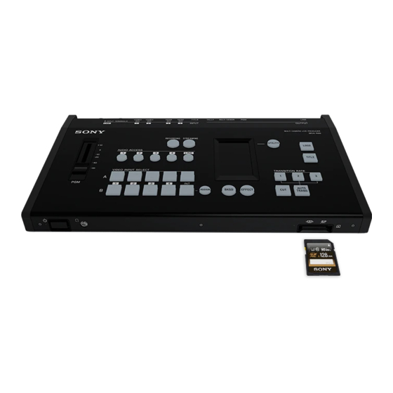
- Page 1 4-689-392-11 (1) Multi Camera Live Producer Operating Instructions MCX-500 Ver. 1.0 © 2016 Sony Corporation...
-
Page 2: Table Of Contents
Table of Contents Important Notes ..............3 Trademarks Chapter 5: Streaming NOTICE TO USERS © 2016 Sony Corporation. All rights reserved. Chapter 1: Introduction Streaming .................54 ˎ “AVCHD Progressive” and “AVCHD Progressive” ˎ This manual or the software described herein,... -
Page 3: Important Notes
Security Condensation The images used in this manual are created to aid SONY WILL NOT BE LIABLE FOR DAMAGES OF ANY in explaining operations. The actual images that If the unit is suddenly taken from a cold to a warm... -
Page 4: Chapter 1: Introduction
Features and Capabilities The MCX-500 Multi Camera Live Producer is a compact switcher that allows video switching and audio mixing via simple operations without expert knowledge. Live controls via a computer is also possible using the unit's live Internet distribution function. The unit can be used in a wide variety of venues for events, seminars, etc. - Page 5 “Customizing the Pattern Icons” (page 39) You can overlay text (i.e., images) created on a computer connected to the TITLE (RGB) input connector on the rear of the unit onto the PGM MCX-500 Computer used for text input output video. Overlay text with ease.
- Page 6 PGM output. The files recorded you can simultaneously control recording start/stop operations on the cameras via recording start/stop to the memory card can be played back or edited on a computer using Sony PlayMemories Home. controls performed on the unit.
-
Page 7: Parts Identification
Chapter 1: Introduction Parts Identification When an audio input is being used for Menu panel (touch panel) Control Panel PGM output, the corresponding button Displays a menu based on the operation or lights. function being performed. You can perform transition or composite Video switching, audio mixing, and other live controls are performed via the control panel. - Page 8 Chapter 1: Introduction: Parts Identification ASSIGN button UTILITY button Transition block Allows you to adjust the headphone volume, brightness of the menu panel and control buttons, etc. Allows you to perform transition (video Allows you to change the video input Pressing the button displays the [UTILITY] menu in the menu panel.
- Page 9 Chapter 1: Introduction: Parts Identification TRANSITION RATE buttons 1 to 3 Front Allows you to select from three presets for the PGM video transition rate by pressing the respective button. You can change the transition rate presets assigned to buttons 1 to 3. For details on settings, see “Changing the Transition Rates”...
- Page 10 Chapter 1: Introduction: Parts Identification Rear For details on connections, see “Connecting Devices” (page 18). PGM HDMI output connector (Type A) Video input block Outputs the finished video processed OPTION connector (RS-232C) internally on the unit (i.e., PGM video) as an Connect a Remote Commander here when HDMI signal.
- Page 11 Chapter 1: Introduction: Parts Identification HDMI input connectors 3 and 4 (Type A) STREAMING network connector (RJ-45 Right Side modular jack) Input HDMI signals. When displaying data from a computer When using the Ustream service to stream, connect to the network via this connector. during a presentation, for example, connect to the computer via this For details, see “Chapter 5: Streaming”...
- Page 12 Chapter 1: Introduction: Parts Identification [NEXT] viewer Multi-Viewer Displays the video selected from among the row B buttons as the NEXT output. The following items appear on the external monitor (i.e., the multi-viewer) connected to the MULTI VIEWER connector on the rear of the unit. [PGM] viewer The multi-viewer allows you to monitor the input materials, PGM output video, video selected as the NEXT output, key compositions, unit status, and other Displays the video currently being output as...
- Page 13 Chapter 1: Introduction: Parts Identification Input image Recording format Audio level meters [RECORDING] information Display the audio levels of the PGM output Displays the following information concerning Displays inputs 1 to 4 and the TITLE Displays the currently configured material input signal. within a range of 0 to -60 dB in 16 levels.
- Page 14 Chapter 1: Introduction: Parts Identification [Setup] tab PC UI Displays the [Setup] screen for configuring settings necessary for live control and other system settings for the unit. Preparations, such as unit setting configurations and composite adjustments, are performed using the PC UI.
- Page 15 Chapter 1: Introduction: Parts Identification [Pattern] tab Communication status Displays the [Pattern] screen for performing the following configurations and adjustments. Indicates the status of communication between ˎ Replacing the eight pattern icons used in BKGD mode and EFFECT mode the unit and the computer. ˎ...
-
Page 16: Basics Of Video Switching
Chapter 1: Introduction Basics of Video Switching “Video switching” refers to the process of switching between video images. You can use the unit to switch Key compositing between and mix videos (input signals) from multiple cameras, VTRs, and a computer. By applying video effects, inserting text, and compositing images, you can create diverse and dynamic This is an effect achieved by removing parts of an image and placing the cutout on another image that program outputs. -
Page 17: Bkgd Mode And Effect Mode
Chapter 1: Introduction BKGD Mode and EFFECT Mode Transitions are separated into two categories on the unit, BKGD mode and EFFECT mode. [Tips] If a B video is currently overlaid when you switch from EFFECT mode to BKGD mode, the B video will be disabled automatically. EFFECT mode BKGD mode Use this mode to insert image B onto image A (i.e., for compositing). -
Page 18: Chapter 2: Preparation
000 18 Chapter 2: Preparation Connecting Devices Connect each device to the unit. When linking with a Remote Commander If you have already connected the devices, proceed to “Chapter 3: Basic Operations” (page 29). Use the OPTION cable supplied with the unit to connect the Remote Commander to the unit. Connect the cameras to the Remote Commander and the unit as follows. - Page 19 Chapter 2: Preparation: Connecting Devices Connecting headphones Connecting the Video and Audio Output Devices Connect headphones for audio monitoring to the headphones jack on the front of the unit. Connect projectors, large displays, and other video output devices to the video output connectors on the rear of the unit, and connect PA systems and other audio output devices to the LINE output connectors.
- Page 20 Chapter 2: Preparation: Connecting Devices Connecting to a Network Connecting the Power Supply Use the PC UI network connector on the rear of the unit to connect the PC UI computer. Connect the DC output plug of the supplied AC adapter to the DC IN 12V connector on the rear of For details on connections, see “Connecting a Computer for Settings Configuration”...
-
Page 21: Startup And Shutdown
000 21 Chapter 2: Preparation Startup and Shutdown Configure the current time, and tap Configuring the Initial Settings (First- Second and Subsequent Startup Configure the initial settings. [DONE]. Select the time zone, and tap [DONE]. Time Startup) Press the power switch on the front of the unit to turn on the unit. -
Page 22: Connecting A Computer For Settings Configuration
000 22 Chapter 2: Preparation Connecting a Computer for Settings Configuration This section describes how to connect the unit Connecting in LAN mode Connecting the Computer to the Unit to a PC UI computer that can perform settings configurations and composite adjustments, and Set the computer's network settings to DHCP how to access the unit from a web browser to beforehand. - Page 23 When using Google Chrome, perform the following. Click the lock icon on the left side of the address bar, and click [Details] in the menu that appears. Click [View certificate]. The certificate viewer appears. Reference the [Issued to] item. Sony-MCX-500-<serial number>...
- Page 24 CA certificate issue location. ˎ Register to the hosts file. ˎ After finishing configurations, enter "https:// Sony-MCX-500-<serial number>" in the address bar to access the unit. When access is successful, the [Live] screen of the PC UI appears.
-
Page 25: Assigning Inputs
000 25 Chapter 2: Preparation Assigning Inputs To switch videos and mix audio, the signals from the devices connected to the input connectors on the Default conditions rear of the unit must be assigned to inputs 1 to 4. Under default conditions, the signals are assigned as follows. Video input Audio input Connector... - Page 26 Chapter 2: Preparation: Assigning Inputs For INT Button Option Description Press and light the ASSIGN button. Tap and select (light) the target connector. Tap and select (light) [BLACK] or [COLOR BAR]. 1 and 2 SDI Assigns the materials input to When a connector is selected (lit), it is immediately assigned and its video input the SDI input connectors.
- Page 27 Chapter 2: Preparation: Assigning Inputs Determining whether to use each channel Pre-Adjustments and Settings for Audio Inputs After finishing configurations, press and unlight the ASSIGN button. Specify whether to use or disable each channel. The [INPUT] menu disappears. Press an AUDIO ACCESS button to display the Determine whether to use each channel, adjust input levels, and configure settings for the audio inputs.
- Page 28 Chapter 2: Preparation: Assigning Inputs Adjusting the audio level of each channel Linking embedded audio to its video Adjust the audio level of each channel while To automatically enable or disable embedded viewing the audio level meters in the multi-viewer. audio in response to PGM output, link the Perform the adjustments while considering the embedded audio to its video.
-
Page 29: Chapter 3: Basic Operations
000 29 Chapter 3: Basic Operations Switching Videos This section describes how to switch PGM output videos using simple operations. Check the assigned videos in the [INPUT] viewer of the multi-viewer. Switching via Cuts (Basic Switching) First, let's try switching videos without applying any effects. For details on changing the assigned videos, see “Assigning Inputs”... - Page 30 Chapter 3: Basic Operations: Switching Videos Previewing videos before switching Press the button for the video you want to output next as the PGM output. Preview the video to be output next as the PGM output in the multi-viewer before switching to it. Use the buttons in rows A and B.
- Page 31 Chapter 3: Basic Operations: Switching Videos Applying Transition Effects Use the buttons in rows A and B. The buttons in row B are used to select the video to output next as the PGM output. Now, let's try switching using patterns that slowly transition the current PGM video into the next video. Select the transition pattern here.
- Page 32 Chapter 3: Basic Operations: Switching Videos Press the BKGD button to enable BKGD mode. Tap and select a pattern icon. The pattern icons selectable in BKGD mode are displayed in the menu panel. For details on the modes, see “BKGD Mode and EFFECT Mode” (page 17). Wipe Press the button for the video you want to output next as the PGM output.
- Page 33 Chapter 3: Basic Operations: Switching Videos Press the AUTO TRANS button. The transition starts, and the videos switch. When a link is configured between the video and its embedded audio, the enabling and disabling of the embedded audio is determined by whether the video is being output as the PGM video. For details on settings, see “Linking embedded audio to its video”...
-
Page 34: Compositing Videos
Chapter 3: Basic Operations Compositing Videos Switch to EFFECT mode when you want to use the picture-in-picture (PinP) function, insert a person onto The selected video appears in the [NEXT] Press the AUTO TRANS button. a background, or otherwise use composite effects on videos. viewer of the multi-viewer. -
Page 35: Inserting Text Onto Videos
Chapter 3: Basic Operations Inserting Text onto Videos The procedure will differ depending on the format Using HDMI Input Signals to Insert Text (EFFECT Mode) Select (light) the TITLE button. of the text signal being input from the computer. Perform the following to use EFFECT mode to overlay the text (signal) that is input from a computer connected to an HDMI input connector on the rear of the unit. - Page 36 Chapter 3: Basic Operations: Inserting Text onto Videos When a link is configured between the video Press the EFFECT button to enable EFFECT Tap and select a luminance key pattern icon. and its embedded audio, the enabling and mode. disabling of the embedded audio is determined by whether the video is being output as the PGM video.
-
Page 37: Live Adjustments
Chapter 3: Basic Operations Live Adjustments Switching between Two Devices Adjusting the Headphone Volume Adjusting the Overall Audio Level Adjusting Individual Audio Levels Connected to a Single Input Display the [UTILITY 1/3] menu, tap and select Use the PGM master fader to adjust the PGM When the voice of a speaker or the sound of (light) [HEAD PHONES], and adjust the volume output level. - Page 38 Chapter 3: Basic Operations: Live Adjustments Listening to the Current Audio Input Outputting the Audio Tone Signal Adjusting the Menu Panel Brightness Adjusting the Button Brightness with the PGM Output By tapping and holding [PFL], you can listen to Display the [UTILITY 1/3] menu, tap and select Display the [UTILITY 1/3] menu, tap and select and monitor only the currently selected audio via (light) [DISPLAY BRIGHT], and select the menu...
-
Page 39: Chapter 4: Advanced Operations
000 39 Chapter 4: Advanced Operations Customizing the Pattern Icons Up to eight transition pattern or composite pattern icons can be displayed in the [BKGD] and [EFFECT] Replacing the Pattern Icons in the [BKGD] Menu menus of the menu panel. Under default conditions, the following pattern icons are displayed. BKGD mode EFFECT mode Select the transition patterns you want to display from among the templates. - Page 40 Chapter 4: Advanced Operations: Customizing the Pattern Icons Select the composite pattern icon you Replacing the Pattern Icons in the [EFFECT] Menu Removing Pattern Icons want to replace. Select [Template] in the [Property] area menu. Select the composite patterns you want to display from among the PinP, chroma key, and luminance key You can remove pattern icons that you do not Pattern icons appear in the editing area on templates.
- Page 41 Chapter 4: Advanced Operations: Customizing the Pattern Icons Rearranging Pattern Icons Enable [Move] mode, and then drag and drop the pattern icon to the desired position. After finishing configurations, select [Done]. After finishing configurations, select [Done]. The arrangement of the pattern icons displayed in the menu is changed.
-
Page 42: Selecting Picture-In-Picture (Pinp) Patterns
Chapter 4: Advanced Operations Selecting Picture-in-Picture (PinP) Patterns This section describes preparations for video composites that use PinP. Overlay video selected in row B Background video selected in row A PinP is a composite effect that inserts an overlay video (B) onto a background video (A). A (background video) B (overlay video) Thirty-three PinP patterns are available on the unit. - Page 43 Chapter 4: Advanced Operations: Selecting Picture-in-Picture (PinP) Patterns Select the PinP pattern icon. Page 3 (3/3) There are three pages of PinP pattern Pattern icons for an SD angle of view. Useful tip icons. Selecting [Next] displays the next page, If you want to display the PinP insert image while selecting [Prev] returns to the (video B) in full screen, select the following...
-
Page 44: Adjustments For Inserting People Onto
Chapter 4: Advanced Operations Adjustments for Inserting People onto Backgrounds (Chroma Key) This section describes preparations for video composites that use chroma keying. Overlay video selected in row B Background video selected in row A Chroma keying is a compositing technique that involves removing a specified color in the overlay video (green in the following example) and overlaying the remaining parts of the video (a person in the following example) onto the background video. - Page 45 Chapter 4: Advanced Operations: Adjustments for Inserting People onto Backgrounds (Chroma Key) Select the chroma key pattern icon. [Bottom]: Specifies the bottom edge of Move the sample mark to select the color that Select [Crop] to crop unnecessary areas of the the used video as a value between [Tips] will be removed for the composite.
-
Page 46: Adjustments For Inserting Text Onto Videos
Chapter 4: Advanced Operations Adjustments for Inserting Text onto Videos Two methods are available for inserting text onto [Tips] Using RGB Input Signals to Insert Text Select (light) the TITLE button. Create text with sufficient space around the top and bottom videos. - Page 47 Chapter 4: Advanced Operations: Adjustments for Inserting Text onto Videos Using HDMI Input Signals to Insert Text (EFFECT Mode) Select [Title] in the [Setup] screen of the PC UI, and adjust the text composition. Perform adjustments while viewing the PGM output video in the multi-viewer. [Key Adjust] Luminance key patterns are used when inserting text with EFFECT mode.
- Page 48 Chapter 4: Advanced Operations: Adjustments for Inserting Text onto Videos Select the luminance key pattern icon. Key video selected in row B Video selected in row A Press the CUT or AUTO TRANS button. The transition starts, and the videos are composited.
-
Page 49: Changing The Transition Rates
Chapter 4: Advanced Operations Changing the Transition Rates Under default conditions, transition rates of 0.5, 1.0, and 1.5 seconds are assigned to TRANSITION RATE Select [Transition Rate] in the [Setup] screen of the PC UI. buttons 1 to 3, but you can change the rates if necessary. [Setup] tab Change the transition rates assigned to these buttons. -
Page 50: Linking To Cameras
Commander. Supported models Support for the following models has been verified as of January 2017. Remote Commander Sony RM-30BP For the latest information on supported models, contact your local Sony representative. Camera Model Function Camcorders supporting LANC connection Simultaneous recording start/stop control... - Page 51 Chapter 4: Advanced Operations: Linking to Cameras Assigning cameras Timecode settings must be configured to perform simultaneous recording controls. Make sure the following settings on the unit and each camera match. ˎ TC FORMAT (DF/NDF) ˎ To perform simultaneous recording controls and light PGM/NEXT tallies by linking with the Remote ˎ...
-
Page 52: Useful Functions (Utilities)
Chapter 4: Advanced Operations Useful Functions (Utilities) The unit's [UTILITY] menu allows you to adjust the unit's settings, format memory cards, and perform Formatting Memory Cards Display the [UTILITY 2/3] menu, and tap other operations. [FORMAT MEDIA]. Format the memory card that will be used for Displaying the [UTILITY] Menu recording the PGM output. - Page 53 Chapter 4: Advanced Operations: Useful Functions (Utilities) Restoring Factory Default Conditions Changing the Display Language Select the display language for the unit’s menus Display the [UTILITY 2/3] menu, and tap and messages with [LANGUAGE]. [INITIALIZE]. A confirmation message appears. For details on changing the display language for the PC UI, see “Display language”...
-
Page 54: Chapter 5: Streaming
000 54 Chapter 5: Streaming Streaming You can stream PGM videos using the Ustream Configuring the basic information on the unit Changing accounts service. Limitations and restrictions for streaming videos Use the PC UI to configure the basic information necessary for streaming transmissions via the unit. Select [Change], and change the user name in the also apply on the Ustream side. - Page 55 Chapter 5: Streaming : Streaming Stopping transmissions Starting and Stopping Streaming Check the channel to be transmitted. Transmissions Tap [STOP]. Transmission controls are performed on the control panel. Starting transmissions Press the STREAMING button. The channel specified as the default will be selected in the [STREAMING] menu.
-
Page 56: Chapter 6: Recording
000 56 Chapter 6: Recording Recording the PGM Output You can record PGM outputs to memory cards. Removing memory cards Preparation Inserting Memory Cards By linking with a Remote Commander, you can have recording start/stop controls on cameras Gently press the memory card inward once, and coincide with recording start/stop controls then remove it. - Page 57 Chapter 6: Recording: Recording the PGM Output You can select from the following formats depending on the system format. Estimated video recording times Configure the each item. When the system format is 1080/50i (Unit: minutes) Recording format Bit rate Picture size 16 GB 1080/50i FX...
- Page 58 Tap [STOP ]. Connect the unit to the computer via a USB connection, and operate the memory card Sony PlayMemories Home is required to play back inserted in the unit as a drive on the computer. Starting recording or edit files recorded with the unit.
- Page 59 Chapter 6: Recording: Recording the PGM Output When the connection is established, the Disconnect the computer that is connected following message appears in the menu panel via the USB cable. and USB connection mode is enabled. Operation of the memory card inserted in the unit as a drive is now possible.
-
Page 60: Transmission
000 60 Chapter 7: Settings Configuring the Network Settings for Streaming Transmission To perform streaming transmissions, configure the settings for connecting the unit to the external Resetting Network Settings and Select [Set]. network. [Tips] Streaming Settings PGM outputs from the HDMI output connector will stop during the few seconds before settings are applied after selecting [Set]. -
Page 61: Configuring The System Settings
Chapter 7: Settings Configuring the System Settings You can view input settings, configure output [SD Aspect]: Specifies the output method for [Output] Screen [System] Screen settings, and configure the unit's system settings SD signals. in the [Setup] screen of the PC UI. [Letter Box]: The [Output] screen allows you to configure The [System] screen allows you to configure the... -
Page 62: Chapter 8: Appendix
000 62 Chapter 8: Appendix Transition and Composite Patterns List Transition patterns Composite patterns (BKGD mode) (EFFECT mode) PinP Pattern icons for HD angle of view Chroma key Select these when you want to shift the row A material to the right or left. 1 pattern 33 patterns 5 patterns... -
Page 63: Troubleshooting
If a problem occurs during operation of the unit, a message will appear in the menu panel and the PC UI. Check the following before requesting repairs. If the problem persists, contact your local Sony Check the content of the message and respond accordingly. If the problem persists, write down the displayed representative. - Page 64 Chapter 8: Appendix: Troubleshooting Symptom Possible cause Solution Symptom Possible cause Solution Text cannot be inserted using The output resolution of the Use a computer with an output resolution of 1600×1200 (60p). Camera control from the The remote control settings have Configure the remote control settings.
-
Page 65: Maintenance And Usage Precautions
ˎ Video files can be damaged in the following ˎ The surface of the LCD has a coating that can peel Audio: LPCM 2ch cases. Sony will not be liable for damaged data Video compatibility Storage media: Memory card resulting from circumstances of any kind. - Page 66 Usage precautions ˎ Back up data frequently to prevent data loss. ˎ Sony will not be liable for loss of data resulting Supported Memory Sticks from circumstances of any kind. ˎ ˎ Under copyright law, you may not use recorded...
-
Page 67: Specifications
THE WARRANTY, OR FOR ANY OTHER REASON AC adapter (1) WHATSOEVER. Video output Codec Format / Protocol USB cable (1) ˎ SONY WILL NOT BE LIABLE FOR CLAIMS OF ˎ AVC/RTMP (Ustream) OPTION cable (1) ANY KIND MADE BY USERS OF THIS UNIT OR HD SDI BNC (1) (PGM) 75 Ω, 1.5 Gbps... - Page 68 Chapter 8: Appendix: Specifications HDMI input connectors 3 and 4 Supported Input Formats Video SDI input connectors 1 to 4 Resolution Frequency / ip When the system format is 1080 50i 720×576 (SD) Video 1280×720 (HD) HD/SD Resolution Frequency / ip 1920×1080 (HD) When the system format is 1080 50i 1920×1080 (HD)
- Page 69 Chapter 8: Appendix: Specifications Supported Output Formats Resolution Frequency / ip 1920×1080 (HD) 59.94i 1920×1080 (HD) 59.94p Edge Crop: PGM SDI output connector Audio Video 16-bit, 48 kHz, 2 ch (fixed) Resolution Frequency / ip MULTI VIEWER HDMI output connector When the system format is 1080 50i 1920×1080 When the system format is 1080 60i...
- Page 70 Chapter 8: Appendix: Specifications File Formats Streaming function Recording function Video Frame rate When the system format is 50i: 25 fps When the system format is 60i: 30 fps Recorded video format Bit rate When the streaming video size is 640×360: 1 Mbps Determined by the [FILE FORMAT] setting in the [RECORDING] menu.
- Page 71 Chapter 8: Appendix: Specifications Pin Assignments TALLY connector 1 2 3 4 5 6 7 8 9 Pin No. Description Function Target Specifications PGM OUT TALLY INPUT1 (SDI) On: SHORT, Off: OPEN PGM OUT TALLY INPUT2 (SDI) On: SHORT, Off: OPEN PGM OUT TALLY INPUT3 (SDI) On: SHORT, Off: OPEN...
-
Page 72: Notes On The Licenses
Source code is provided on the web. FOR ANY OTHER USE. Use the following URL to download it. ADDITIONAL INFORMATION MAY BE OBTAINED http://oss.sony.net/Products/Linux/ FROM MPEG LA, L.L.C. We would prefer you do not contact us about the SEE <HTTP://WWW.MPEGLA.COM>... -
Page 73: Glossary
Chapter 8: Appendix Glossary Chroma keying Encoding Monitor A method of compositing images that removes Data rate conversion that uses compression Viewing video or listening to audio. Alternatively, a A 3-pin connector, often called a Cannon components in the foreground image that contain technology and is performed based on the device for viewing and listening. -
Page 74: Index
Chapter 8: Appendix Index Aspect ratio ..................61 HDMI input connectors ............11 OPTION connector ..............10 SDI input connectors ..............10 ASSIGN button .................. 8 HDMI signal format ..............61 Output format support ............. 69 SD signals ..................61 AUDIO ACCESS buttons .............. - Page 75 Chapter 8: Appendix: Index VIDEO input connectors ............10 VIDEO INPUT SELECT ..............8 Video selection buttons .............. 8 Wipe ...................... 31...
Need help?
Do you have a question about the MCX-500 and is the answer not in the manual?
Questions and answers