Table of Contents
Advertisement
Quick Links
Advertisement
Table of Contents

Subscribe to Our Youtube Channel
Related Manuals for RS ISR-6051

Summary of Contents for RS ISR-6051
- Page 1 Instruction Manual ISR-6051 Dual Channel Oscilloscope...
- Page 2 This manual contains proprietary information, which is protected by copyrights. All rights are reserved. No part of this manual may be photocopied, reproduced or translated into another language without prior written consent of RS Components. The information in this manual was correct at the time of printing. Due to...
-
Page 3: Table Of Contents
ISR-6051 OSCILLOSCOPE USER MANUAL CONTENTS PAGE 1. PRODUCT INTRODUCTION ..............1 1-1. D ..................... 1 ESCRIPTION 1-2. F ....................2 EATURES 2. TECHNICAL SPECIFICATIONS ............4 3. PRECAUTIONS BEFORE OPERATION ..........7 3-1. U .............. 7 NPACKING THE OSCILLOSCOPE 3-2. C ............ -
Page 4: Safety Terms And Symbols
ISR-6051 OSCILLOSCOPE USER MANUAL SAFETY TERMS AND SYMBOLS These terms may appear in this manual or on the product: WARNING. Warning statements identify conditions or practices that could result in injury or loss of life. CAUTION. Caution statements identify conditions or practices that could result in damage to this product or other property. - Page 5 ISR-6051 OSCILLOSCOPE USER MANUAL FOR UNITED KINGDOM ONLY NOTE: This lead/appliance must only be wired by competent persons WARNING: THIS APPLIANCE MUST BE EARTHED IMPORTANT: The wires in this lead are coloured in accordance with the following code: Green/ Yellow:...
- Page 6 ISR-6051 OSCILLOSCOPE USER MANUAL This cable/appliance should be protected by a suitably rated and approved HBC mains fuse: refer to the rating information on the equipment and/or user instructions for details. As a guide, cable of 0.75mm should be protected by a 3A or 5A fuse. Larger conductors would normally require 13A types, depending on the connection method used.
-
Page 7: Product Introduction
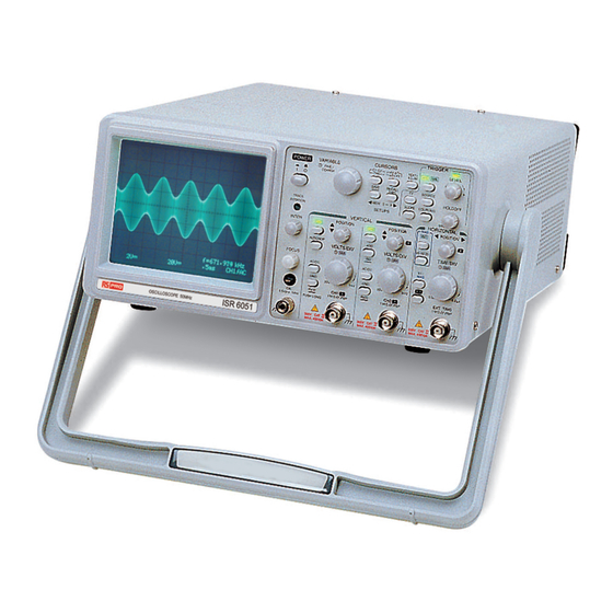
USER MANUAL 1. PRODUCT INTRODUCTION 1-1. Description The ISR-6051 oscilloscope is a 50 MHz, two-channel, portable oscilloscopes for general purpose use. A microprocessor-based operating system controls most of the functions of the instrument, including cursor readout and digitized panel setting. On-screen alphanumeric readout and cursor functions for voltage, time and frequency measurement provide operational convenience. -
Page 8: Features
ISR-6051 OSCILLOSCOPE USER MANUAL 1-2. Features The oscilloscope offers several additional features: High intensity and internal graticule CRT; The oscilloscope employs a high intensity 6-inch rectangular screen cathode-ray tube with red internal graticule. It displays clear readable traces even at high sweep speeds. Internal graticule lines eliminate parallax-viewing error between the trace and the graticule line. - Page 9 ISR-6051 OSCILLOSCOPE USER MANUAL CH1 Signal output: The CH1 signal output is obtained by splitting the input signal in the middle of the signal line. As the connector provides the input signal at a level of 50mV/div, connecting a frequency counter makes it possible to measure the frequency of a very low-level signal while observing its waveform.
-
Page 10: Technical Specifications
ISR-6051 OSCILLOSCOPE USER MANUAL 2. TECHNICAL SPECIFICATIONS 6-inch rectangular type with internal graticule; Type 0%, 10%, 90% and 100% markers. 8 x 10 DIV (1 DIV = 1 cm) Accelerating potential Approx. 10kV INTEN and FOCUS Front panel control. Illumination... - Page 11 ISR-6051 OSCILLOSCOPE USER MANUAL Trigger modes AUTO, NORM, TV Trigger source VERT-MODE, CH1, CH2, LINE, EXT. Trigger coupling AC, HFR, LFR, TV-V(-), TV-H(-). “+” or “- ” polarity. Trigger slope CH1, VERT- MODE 20Hz~5MHz 0.5 DIV 2.0 DIV 200mV 5MHz~40MHz 1.5 DIV 3.0 DIV...
- Page 12 ISR-6051 OSCILLOSCOPE USER MANUAL AC100V, 120V, 230V ±10% selectable. Voltage LINE POWER Frequency 50Hz or 60Hz. REQUIREMENT Power Consumption Approx. 60VA, 50W(max). MECHANICAL Dimensions 275(W)×130(H)×370(D) mm. SPEC. Weights 8 kg OPERATING Indoor use ENVIRONMENT Altitude up to 2000 m Ambient temperature : To satisfy specifications : 10℃...
-
Page 13: Precautions Before Operation
ISR-6051 OSCILLOSCOPE USER MANUAL 3. PRECAUTIONS BEFORE OPERATION 3-1. Unpacking the oscilloscope The product has been inspected and tested before shipment from the factory. Upon receiving the instrument, please unpack and inspect it to check for any damage caused during transportation. If any sign of damage is found, notify the bearer and/or the supplier immediately. -
Page 14: Environment
ISR-6051 OSCILLOSCOPE USER MANUAL 3-3. Environment The normal operating ambient temperature range of this instrument is from 0 to 40C (32 to 104F). Operation outside this temperature range may cause damage to the instrument. Do not use the instrument where strong magnetic or electric fields exist, as it may disturb the operation and measurement. -
Page 15: Front And Rear Panels
ISR-6051 OSCILLOSCOPE USER MANUAL 4. FRONT AND REAR PANELS When the instrument is switched on, all significant settings are displayed on the CRT screen. The LED’s located on the front panel assist operation and indicate additional information. Incorrect operation and the electrical end position of control knobs is indicated by a warning beep. - Page 16 ISR-6051 OSCILLOSCOPE USER MANUAL Front panel 10 ...
-
Page 17: Front Panel
ISR-6051 OSCILLOSCOPE USER MANUAL 4-1. Front panel Display controls The display controls adjust the on-screen appearance of the waveform and provide a probe compensation signal source. ... - Page 18 ISR-6051 OSCILLOSCOPE USER MANUAL (3) INTEN—Control knob This control knob is used for adjusting the intensity of the traces. Turn the knob clockwise to increase the intensity and turn it anti -clockwise to decrease the intensity. (4) FOCUS This control knob allows the trace and other information on the CRT to be focussed for best resolution.
- Page 19 ISR-6051 OSCILLOSCOPE USER MANUAL △V: Two horizontal cursors appear. The voltage between the two cursors is calculated according to the setting of VOLTS/DIV, and displayed with △V at the top of the CRT. △T: Two vertical cursors appear. The time difference between the two cursors is calculated according to the setting of TIME/DIV, and displayed with △T at the top of the CRT.
- Page 20 ISR-6051 OSCILLOSCOPE USER MANUAL (10) ◄MEMO- 9►—SAVE/RECALL The instrument contains 10 non-volatile memories which can be used to save instrument setting and to recall them. The memories will store all controls settings that are electronically selected. Press the ◄ or ► button to select the required memory location. The display then indicates the letter “M”...
-
Page 21: Vertical Controls
ISR-6051 OSCILLOSCOPE USER MANUAL Vertical controls The vertical controls select the displayed signals and control the amplitude characteristics. 12 14 ... - Page 22 ISR-6051 OSCILLOSCOPE USER MANUAL (15) ALT/CHOP This button has two functions, which are required and available only when both channels are active. ALT—Displays in the readout and indicates alternate channel switching. After each time base sweeps, the instrument internally switches over from channel 1 and channel 2 and vice versa.
- Page 23 ISR-6051 OSCILLOSCOPE USER MANUAL The deflection coefficients and additional information regarding t he active channels are displayed in the CRT readout. Press the VOLTS/DIV control knob to select the VOLTS/DIV function between attenuator and vernier (variable). The current setting is displayed by the “>”...
-
Page 24: Horizontal Controls
ISR-6051 OSCILLOSCOPE USER MANUAL (23) CH1-X—Input BNC socket This BNC socket is the signal input for channel 1. In X-Y mode, signals at this input are used for the X deflection. The outer (ground) connection is galvanically connected to the instrument ground and consequently to the safety earth contact of the mains plug. - Page 25 ISR-6051 OSCILLOSCOPE USER MANUAL (25) H POSITION This control knob enables a horizontal position shift of the signals. In combination with the MAG control, the function makes it possible to shift any part of the signal on to the screen.
- Page 26 ISR-6051 OSCILLOSCOPE USER MANUAL (28) ×1/MAG Press the button the select the sweep time between ×1 (normal) and MAG (magnify). If the MAG function is selected, the signal display will be expanded and consequently only a part of the signal trace is visible on the CRT.
-
Page 27: Trigger Controls
ISR-6051 OSCILLOSCOPE USER MANUAL Trigger controls The trigger controls determine the sweep start timing for both signals. Ω (30) ATO/NML – Button and indicator LEDs. - Page 28 ISR-6051 OSCILLOSCOPE USER MANUAL (31) SOURCE—Button Press the button to select the trigger signal source. The actual setting is indicated in the CRT readout (“SOURCE”, slope, coupling). Each time the button is pressed, the trigger source changes in the sequence: VERT—CH1—CH2—LINE—EXT—VERT...
- Page 29 ISR-6051 OSCILLOSCOPE USER MANUAL (32) TV—Button for video sync signal selection Separates the video sync signal from the composite waveform and directs it to the triggering circuit. The horizontal or vertical sync signals are selected by the TV button. The current setting is displayed in the CRT readout under item (source, video polarity, “TVV or TVH”).
- Page 30 ISR-6051 OSCILLOSCOPE USER MANUAL (34) COUPLING— Press the button to select the trigger coupling. The actual setting is indicated in the CRT readout (source, slope “COUPLING”). Each time the COUPLING button is pressed, the trigger coupling changes in the sequence: AC—HFR—LFR—AC...
- Page 31 ISR-6051 OSCILLOSCOPE USER MANUAL (35) TRIGGER LEVEL—Control knob with TRG LED Turn the control knob to change the trigger point (voltage) and set to a suitable position for the start of triggered sweep of the waveform. Rotate the control knob clockwise and the trigger point moves toward the positive peak of the trigger signal.
-
Page 32: Rear Panel
ISR-6051 OSCILLOSCOPE USER MANUAL 4-2. Rear Panel The rear panel provides input power and additional signal connections. 38 39 ENSURE THE POWER IS REMOVED FROM THE INSTRUMENT BEFORE REPLACING THE FUSE LINE VOLTAGE RANGE WARNING FUSE SELECTION (50/60Hz) 90~110V 100V T 1.0A... - Page 33 ISR-6051 OSCILLOSCOPE USER MANUAL (41) Z-Axis Input—BNC socket Connect external signals to the Z-axis amplifier for intensity modulating the CRT display. This terminal is DC-coupled. The intensity is reduced by a positive signal, while it is increased by a negative signal.
-
Page 34: Operation
ISR-6051 OSCILLOSCOPE USER MANUAL 5. OPERATION This section contains basic operation information and techniques that should be considered before proceeding with any measurements. For the location and function of instrument controls, connectors, and indicators, refer to the instructions for “Front Panel” and “Rear Panel” of this manual. - Page 35 ISR-6051 OSCILLOSCOPE USER MANUAL Figure 5-1 Readout Layout 29 ...
-
Page 36: Connecting Input Signals
ISR-6051 OSCILLOSCOPE USER MANUAL 5-2. Connecting input signals Grounding The most reliable signal measurements are made when the oscillosco pe and the unit under test are connected by a common reference (ground lead) in addition to the signal lead or probe. The ground lead of the probe provides the best grounding method for signal interconnection and ensures the maximum amount of signal-lead shielding in the probe cable. -
Page 37: 5-3.Adjustments And Checks
ISR-6051 OSCILLOSCOPE USER MANUAL 5-3.Adjustments and checks Trace rotation adjustment Normally, when the trace is in parallel with the centre horizontal graticule line, there will be no need to adjust the TRACE ROTATION. If necessary, adjust the TRACE ROTATION to make the baseline trace parallel to the centre horizontal graticule line by using a small straight-blade screwdriver or alignment tool. - Page 38 ISR-6051 OSCILLOSCOPE USER MANUAL 7) Observe the displayed waveform and compare it with the waveforms shown in figure 5-2. If the probe needs to be adjusted, proceed as detailed in step 8. If either probe does not need to be adjusted, proceed with “Function Check”.
-
Page 39: Function Check
ISR-6051 OSCILLOSCOPE USER MANUAL 5-4. Function check Before using the oscilloscope to make measurements, check the instrument operates correctly as follows: Connect the × 10 probes to CH1 and CH2 inputs. Connect the probe tips to the CAL test point of the oscilloscope. - Page 40 ISR-6051 OSCILLOSCOPE USER MANUAL Figure 5-3 Set both CH1 and CH2 COUPLING to GND. Use the CH1 and CH2 POSITION controls to align both traces on the centre graticule. Operate the CH2 INV by pressing and holding the button. Set to the ADD mode by pressing the ADD button briefly.
- Page 41 ISR-6051 OSCILLOSCOPE USER MANUAL Figure 5-4 ADD mode 10) Turn off the ADD mode by pressing the ADD button briefly. 11) Turn off the CH2 INV by pressing and holding the button. 35 ...
-
Page 42: Basic Operation
ISR-6051 OSCILLOSCOPE USER MANUAL 5-5. Basic operation Displaying CH1 or CH2 To display the signal from a signal channel, briefly press the CH1 or CH2 button to set the oscilloscope to channel 1 or channel 2 mode. Displaying CH1 and CH2 To display both signals at the same time, proceed as following: Set the CH1 and CH2 on. - Page 43 ISR-6051 OSCILLOSCOPE USER MANUAL Displaying the sum or difference of CH1 and CH2 To display the algebraic sum or difference of CH1 and CH2, proceed as follows: Set the ADD button to ADD mode. Figure 5-6 below shows the sum of the waveforms from figure 5-5.
- Page 44 ISR-6051 OSCILLOSCOPE USER MANUAL Comparing frequency and phase (X-Y Operation) Comparison of the frequency and phase of two signals can be made by using the X-Y mode. The X-Y waveform displays different amplitude, frequency, and phase. The figure 5-7 shows a typical waveform made up of two signals...
- Page 45 ISR-6051 OSCILLOSCOPE USER MANUAL Magnifying waveform events Use the MAG button to view small portions of a waveform which are too far from the starting point to view by using the TIME/DIV control. To use the MAG button, proceed as follows: Adjust the TIME/DIV to the fastest sweep that displays the event.
- Page 46 ISR-6051 OSCILLOSCOPE USER MANUAL MAG-ALT function input signal displayed pressing MAG(magnify) MAG-ALT(LED lit) buttons: Set the required portion of the waveform to the centre of the screen for magnification. The magnified waveform appears approximately 3 divisions below the normal (×1) waveform.
- Page 47 ISR-6051 OSCILLOSCOPE USER MANUAL Operating hold-off time control When the measured signal is a complex waveform with two or more repetition frequencies (period), triggering with the LEVEL control alone may not be sufficient to attain a stable waveform display. A stable sweep can be obtained if synchronized to the measured signal waveform by adjusting the hold-off time of the sweep waveform.
- Page 48 ISR-6051 OSCILLOSCOPE USER MANUAL Observing the synchronization of two waveforms When two signals of CH1 and CH2 have the same frequencies with an integral number, or a specific time difference, the SOURCE selects either CH1 or CH2 as a reference signal. Select CH1 signal from CH1 position and select CH2 signal from CH2 position as a reference.
- Page 49 ISR-6051 OSCILLOSCOPE USER MANUAL The VERT-MODE triggering is not possible when the signal is applied only to one channel as shown in Figure 5-12 below: Figure 5-12 Trig. Source on VERT. one channel ALTERNATE TRIGGER The jittering wave as shown in Figure 5-13 may appear on the screen when a gently-sloping signal displays approximately 10 cycles or less by setting VERT-MODE to SOURCE, and setting ALT/CHOP button to ALT.
- Page 50 ISR-6051 OSCILLOSCOPE USER MANUAL Triggering of video signal In television related applications, complex waveforms containing video signals, blanking, pedestal and synchronizing signal often require measurement Press the TV button to set to TV mode. The built -in active TV sync-separator separates the frame or line sync-pulses from the video signal.
-
Page 51: Measurement Applications
ISR-6051 OSCILLOSCOPE USER MANUAL 5-6. Measurement applications The oscilloscope has a cursor measurement system for making accurate, direct-readout voltage, time frequency measurements. measurements described in this section are examples of typical applications using this measurement system. After becoming familiar with the controls, indicators, and capabilities of the instrument, you can develop techniques to make measurement in specific applications. - Page 52 ISR-6051 OSCILLOSCOPE USER MANUAL Figure 5-16: Cursor Measurement (a).Typical △V (Voltage difference) for AC voltage. When both CH1 and CH2 are turned on, the measurement value is with reference to CH1(△V1). (b).Typical △T (Time difference) cursor measurement for rise time.
-
Page 53: Maintenence
To avoid electrical shock, do not perform any servicing other than that detailed in these instructions. For repair and maintenance other than as detailed in these instructions, contact the supplier or RS Components, the address is given at the end of these instructions. -
Page 54: Cleaning
ISR-6051 OSCILLOSCOPE USER MANUAL Reconnect the power cord, turn the instrument on and check for correct operation. 6-3. Cleaning To clean the oscilloscope, use a soft cloth dampened in a solution of mild detergent and water. Do not spray cleaner directly onto the oscill oscope, as it may leak into the cabinet and cause damage. -
Page 55: Block Diagram
ISR-6051 OSCILLOSCOPE USER MANUAL 7. Block diagram 49 ... - Page 56 RS Components shall not be liable for loss of use of the instrument or other incidental or consequential damages, expenses, or economic loss, or for any claim or claims for such damage, expense or economic loss.
- Page 57 Africa RS Components SA P.O. Box 12182, Vorna Valley,1686 20 Indianapolis Street, Kyalami Business Park, Kyalami, Midrand, South Africa Asia RS Components Pte Ltd. 21 Tech Park Crescent Singapore 638040 China RS Components Ltd. Suite 23 A-C East Sea Business Centre Phase 2 No.
Need help?
Do you have a question about the ISR-6051 and is the answer not in the manual?
Questions and answers