Table of Contents
Advertisement
Quick Links
WARNING
This symbol is intended to alert the user to the presence of unprotected
"Dangerous voltage" within the product's enclosure that may be strong
enough to cause a risk of electric shock.
WARNING
TO REDUCE THE RISK OF FIRE OR ELECTRIC SHOCK, DO NOT EXPOSE THIS
APPLIANCE TO RAIN OR MOISTURE.
NOTE: This equipment has been tested and found to comply with the limits for a class
digital device, pursuant to part 15 of the FCC Rules. These limits are designed to provide
reasonable protection against harmful interference when the equipment is operated in a
commercial environment. This equipment generates, uses, and can radiate radio frequency
energy and, if not installed and used in accordance with the instruction manual, may cause
harmful interference to radio communications. Operation of this equipment in a residential
area is likely to cause harmful interference in which case the user will be required to correct
the interference at his own expense.
Disposal of Old Electical & Electronic Equipment
(Applicable in the European Union and other European countries with separate
collection systems)
This symbol on the product or on its packaging indicates that this product shall not be treated as
household waste. Instead it shall be handed over to the applicable collection point for the recycling
of electrical and electronic equipment. By ensuring this product is disposed of correctly, you will
help prevent potential negative consequences for the environment and human health, which could
otherwise be caused by inappropriate waste handling of this product. The recycling of materials will
help to conserve natural resources. For more detailed information about recycling of this product,
please contact your local city office , your household waste disposal service or the shop where you
purchased the product.
This symbol is intended to alert the user to the presence of
important operating and maintenance (servicing)
instructions in the literature accompanying the appliance.
1
Advertisement
Chapters
Table of Contents

Related Manuals for Artnix ANX-16120

Summary of Contents for Artnix ANX-16120
- Page 1 WARNING This symbol is intended to alert the user to the presence of unprotected “Dangerous voltage" within the product's enclosure that may be strong enough to cause a risk of electric shock. This symbol is intended to alert the user to the presence of important operating and maintenance (servicing) instructions in the literature accompanying the appliance.
- Page 2 PRECAUTION All the safety and operating instructions must be read before the unit is operated. • Make sure to switch the power off before you install the DVR. • There is the danger of an electric shock if the DVR is opened by an unqualified service engineer or installer.
-
Page 3: Table Of Contents
CONTENTS 1. FEATURE LIST ---------------------------------------------------------------------------------- 2. PACKING DETAIL ------------------------------------------------------------------------------------------ 3. LOCATION AND CONTROL ----------------------------------------------------------------- 3.1 FRONT PANEL CONTROLS ------------------------------------------------------------------------------- 3.2 REAR PANEL CONNECTORS ----------------------------------------------------------------------------- 4. INSTALLATION --------------------------------------------------------------------------------------------- 4.1 TOTAL CONNECTION LAY-OUT ------------------------------------------------------------------------- 4.2 INDIVIDUAL CONNECTION -------------------------------------------------------------------------------- 4.2.1 RACK MOUNT ----------------------------------------------------------------------------------- 4.2.2 CAMERA ------------------------------------------------------------------------------------------ 4.2.3 AUDIO --------------------------------------------------------------------------------------------- 4.2.4 MONITOR -----------------------------------------------------------------------------------------------... - Page 4 CONTENTS 7. EXTERNAL TERMINAL INFORMATION ------------------------------------------------- 7.1~2 RS-422/485 / T.ADJ------------------------------------------------------------------------------------- 7.3~4 RELAYOUT / ALARM ------------------------------------------------------------------------------------ 7.5~6 VGA / SERIAL ----------------------------------------------------------------------------------------- 7.7~8 ETHERNET/USB / REMOTE ---------------------------------------------------------------------- 8. SPECIFICATIONS -------------------------------------------------------------------------- 9. 256 CAMERA INTEGRATION SYSTEM -------------------------------------------------- 10. HDD INSTALLATION ------------------------------------------------------------------------ 10.1 INTERNAL HDD INSTALLATION ------------------------------------------------------------------ 10.2 DVD±RW (or CD-RW)INSTALLATION -------------------------------------------------------------- JUMPER SETTING INFORMATION -------------------------------------------------------- 11.
-
Page 5: Feature List
FEATURES Features Chapter 1 Operation Playback, recording, backup and transmission simultaneously Real time single or multi-screen display 7Pan & Tilt, 2X/4X digital zoom and PIP display Easy operation by Jog shuttle, IR remote controller, external keypad controller and USB 2.0 Mouse Hidden camera option (covert) User-friendly setup menu and operation Playback... -
Page 6: External Storage
FEATURES External storage Automatic backup to selected backup HDD (Event backup/ Mirroring) Own external storage device to extend the HDD capacity You can install 10 HDDs in 1 external HDD Bay and connect up to 4 Bay with this DVR. (250GB X 40HDDs = 10TB, 500GB X 40HDD = 20TB, 1TB X 40HDD = 40TB) Audio 4 channels audio recording in real time... -
Page 7: Packing Detail
PACKING DETAIL Packing Detail Chapter 2 1. DVR 4. Remote controller (Option) 2. Network Viewer Program CD 3. User’s Manual 5. R-HDD Rack Key 6 Rack Mount 7. Power Cord 8. Battery 9. HDD Screw CONTENTS 1. DVR 2. Network Viewer Program CD 3. -
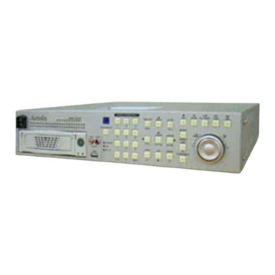
Page 8: Location And Control
LOCATION AND CONTROL Location and Control Chapter 3 3.1 FRONT PANEL CONTROLS ○ ○ ○ ○ ○ ○ ○ ○ ○ ○ ○ ○ ○ ○ ○ ○ ○ ○ ○ ○ ○ ○ ○ ○ ○ ○ ○ Control keys Description Switch to turn the power on / off ○... -
Page 9: Rear Panel Connectors
LOCATION AND CONTROL 3.2 REAR PANEL CONNECTORS ○ ○ ○ ○ ○ ○ ○ ○ ○ ○ ○ ○ ○ ○ ○ ○ ○ ○ ○ ○ ○ ○ Port Name Description BNC input ports for cameras ○ CAMERA IN BNC output(looping) ports for cameras ○... -
Page 10: Installation
INSTALLATION Installation Chapter 4 4.1 TOTAL CONNECTION LAY-OUT XDSL MODEM ETHERNET HUB... -
Page 11: Individual Connection
INSTALLATION 4.2 INDIVIDUAL CONNECTION 4.2.1 Rack mount Adapt the supplied rack mount to DVR Adapt the DVR rack (19 inch) 4.2.2 Camera * Connect a female BNC connector of each camera to a male BNC connector, “CAMERA IN” port. * Connect the looping BNC output to other inputs as required... -
Page 12: Audio
INSTALLATION 4.2.3 Audio (*Refer to the specification) Audio Input - AUDIO IN : Connect the RCA Line Jack of the relevant equipment (for example, a camera with a built-in microphone) to the AUDIO IN port Audio Output - AUDIO OUT : Connect the RCA Line output to a monitor with a built-in speaker NOTE This DVR can be connected only with a line audio and not support a microphone for audio input and output. -
Page 13: Monitor
INSTALLATION 4.2.4 Monitor - Connect the female BNC for monitor output. - Connect the male Y/C cable socket for S-VIDEO monitor output. 4.2.5 Power - Select the correct voltage of power (230=180~265 VAC / 115=90~135 VAC) - Connect the power cord. -
Page 14: External Hdd Bay
INSTALLATION 4.2.6 External HDD Bay (XHD-10U) (USB output) INSTALLATION PROCESS. 1) Turn off the power of DVR. 2) Connect the grounding conductor between DVR and external HDD bay. 3) Connect the USB cable between DVR and external HDD bay. 4) Connect the power cord of DVR and external HDD bay. 5) Plug the power cord of DVR and external HDD bay. -
Page 15: Usb 2.0 Port
INSTALLATION 4.2.7 USB 2.0 ports Three USB ports are provided to connect a USB memory stick, external storage devices and ○ CD-RW/DVD±RW for video clip copying. One USB port is on the front panel and the other two are on the rear panel. ○... -
Page 16: Operation
OPERATION Operation Chapter 5 5.1 FACTORY DEFAULT MENU Setup> QUICK SETUP> QUICK SETUP…………………………..………OFF IMAGE SIZE………………………………………720x240 RECORD FRAME…………………………………240 EVENT……………………….…..…………...ALL PRE RECORD TIME……….……………………..5 POST RECORD TIME………………………..…..10 IMAGE QUALITY.. ………………………………FINE AUDIO RECORD ………………………………….OFF SCREEN> POSITION HORIZONTAL POSITION………………….0 VERTICAL POSITION.……………………..0 AUTO SEQUENCE QUAD-A~E/ NINE-A~B/ SIXTEEN.……...3SEC ADD AUTO SINGLE….…………………...OFF AUTO-SINGLE CH1~16………………..…3SEC VIDEO LOSS SKIP..……………………….ON... - Page 17 AUDIO RECORD AUDIO 1………………..…………………….…..1 AUDIO 2………………..…………………….…..2 AUDIO 3………………..…………………….…..3 AUDIO 4……………..……………………….…..4 AUDIO 5………………..…………………….…..1 AUDIO 6………………..…………………….…..2 AUDIO 7………………..…………………….…..3 AUDIO 8……………..……………………….…..4 (ANX-16120 : 4CH audio) REPEAT RECORD REPEAT RECORD..………………………………..ON REPEAT RECORD ALARM.…………………..…..5% PLAY MODE.…………………………………….……..AUTO BACKUP MODE..……………………………….……..OFF HOLIDAY HOLIDAY RECORD…………………………….….OFF HOLIDAY SETUP(MM/DD) ………………………..00/00 EVENT MOTION DETECTION CHANNEL……………………………………..1...
- Page 18 OPERATION REMOTE CONTROL ID.…………….………..…………..ALL KEY ECHO…..………………….…………………………..ON LANGUAGE……………….………..………………….…….ENGLISH DVR INITIALIZE.………………….………..………………NO FIRMWARE UPGRADE………………….………………..NO LINK> NETWORK DHCP……..……………………………………………OFF RS232C BAUD RATE..………………….……………………..115200 DATA BIT……..……………………………………….8 PARITY BIT….……..…………………………………NONE STOP BIT……..……………………………………….1 RS422/485 SYSTEM ID……..…………………………………….1 OUTPUT MODE.…………………………………….RS-485 BAUD RATE..………………….……………………..115200 DATA BIT……..……………………………………….8 PARITY BIT….……..…………………………………NONE STOP BIT……..……………………………………….1 SEARCH> TIME SEARCH HDD ID………………………………………………..NORMAL CHANNEL…………………..………………….…….ALL EVENT SEARCH HDD ID………………………………………………..NORMAL...
-
Page 19: Front Panel Controls
OPERATION 5.2 FRONT PANEL CONTROLS 5.2.1 POWER ON /OFF After the connection of power cord and other devices with this DVR, turn the power on. a. The video signal system (NTSC or PAL) is automatically detected. b. Power Failure Recovery This DVR automatically reverts back to programmed record parameters upon power restoration. - Page 20 OPERATION Use the +10 Button when you select two digit camera numbers. EX) Camera Number 12 = Press the +10 Button, and then press the No. 2 Button. CAMERA/NUMBER INPUT buttons are used to input the password in the password lock function. 5.2.2.2 Auto Sequence Display <ADD AUTO SINGLE : ON>...
-
Page 21: Record
OPERATION 5.2.3 RECORD Press the REC button and the following message will be displayed as below; MANUAL MODE Press the REC button to begin recording. To stop recording, press the REC button again. The screen will be turned into real time display mode. - Page 22 OPERATION 5.2.4.1 SEARCH & COPY At the SEARCH menu; ① Move the cursor to TIME SEARCH using button. ② Press the ENTER button and TIME SEARCH screen appears. ③ Select the desired HDD ID using the (-) or (+) button. ④...
- Page 23 OPERATION 5.2.4.3 EVENT SEARCH At the SEARCH menu; ① Move the cursor to EVENT SEARCH using button. ② Press the ENTER button and the EVENT SEARCH menu screen appears. ③ Select the desired HDD ID using the (-) or (+) button. ④...
- Page 24 OPERATION ③ Select the desired HDD ID using the (-) or (+) button. ④ Move the cursor to the desired position of SEARCH TIME using the buttons, and then set up the desired time using the(-), (+) buttons. (Or turn the JOG DIAL to search the block list.) ⑤...
-
Page 25: Search Button Information
OPERATION <How to make Bookmark list> ① Press the “PB/PAUSE” button to playback. ② Find the desired image using shuttle ring. ③ Press the “PB/PAUSE” button to see the still picture of the desired image. ④ Press the “PTZ” button to add the BOOKMARK list. 5.2.4.7 LOG FILE SEARCH At the SEARCH menu;... - Page 26 OPERATION 5.2.5.2 PB / PAUSE ( Press this button to begin playback at normal speed (X1). Press this button again to pause the playback. NOTE If you press the “PB” button to playback, it will playback from the end of played final image. <How to playback a section repeatedly>...
-
Page 27: Jog Shuttle Information
OPERATION 5.2.6 JOG SHUTTLE INFORMATION SHUTTLE RING JOG DIAL 5.2.6.1 Normal Playback Mode ① Turn the SHUTTLE ring to the desired playback direction and speed level according to the above drawing during the playback. ② The DVR will go back to the normal playback mode when the SHUTTLE ring is returned to the center position. -
Page 28: Screen Select(Lv/Pb)
OPERATION ② Press the D-ZOOM button. The indication screen appears on the main screen. ③ Turn JOG DIAL or press the buttons to select the desired location. ④ Press the ENTER button to change the zoom x2 ~ x4. ⑤ Press the ESC button to exit this screen. 5.2.8 SCREEN SELECT(LV/PB) ►... -
Page 29: Copy
OPERATION 5.2.10 COPY Press the COPY button to copy the recorded images into other media and the COPY MENU screen appears. 5.2.10.1 COPY 5.2.10.1-1 COPY TO HDD At the COPY menu, ① Move the cursor to COPY using the buttons. ②... - Page 30 OPERATION ④ Move the cursor to HDD ID using the buttons and select the desired HDD to copy among HDD IDs using the (-), (+) buttons or jog dial. ⑤ Move the cursor to the desired position of COPY START TIME/ COPY END TIME using buttons and press the (-) or (+) button to set up the time to set up the COPY START TIME and COPY END TIME.
- Page 31 OPERATION ** Scroll bar: - Turn the shuttle ring to the right to move the cursor of COPY END TIME or to the left to move the cursor of COPY START TIME and the cursor will be yellow. And then turn the Jog dial to move the cursor to the desired time. - It can operate with just Mouse click.
- Page 32 OPERATION When the copy is in process, the copying status(ex. “COPY 30%”) will be displayed on the right side of the monitor. NOTE - CD-RW or DVD±RW is option and this DVR need the interface board to install a built-in CD-RW or DVD±RW.
-
Page 33: Dvr Status
OPERATION 5.2.10.3 MEDIA FORMAT At the COPY menu, ① Move the cursor to MEDIA FORMAT using the buttons. ② Press the ENTER button and the following screen appears. ③ Select formatting media using the (-), (+) button. ④ Move the cursor to MEDIA FORMAT and then press the “ENTER” button. ⑤... - Page 34 OPERATION channel, model name and ID will be displayed on the left side of the monitor as the following picture. ② Press the desired camera button to be displayed. ③ Use the button to pan left and right and the button to tilt up and down.
-
Page 35: Function Button
OPERATION 5.2.13 FUNCTION BUTTON (RESERVED) You need this button to control “USER” mode of RELAY 4 SELECT. Please refer to 6.4.8 RELAY OUTPUT, page 53. 5.2.14 PIP CONTROL ① Select a single camera in live view, and then press the PIP button and the following screen will be displayed. -
Page 36: Remote Controller
OPERATION 5.3 REMOTE CONTROLLER Button Name Description Use in USER mode of RELAY 4 SELECT ○ FUNCTION ○ ○ (PTZ) Select the PTZ mode ○ Zoom out of PTZ ○ ○ ○ IRIS - Iris close of PTZ ○ ○ ○... -
Page 37: Mouse Control
MENU SETUP 5.4 MOUSE CONTROL ○ ○ ○ Status display Double-click of the left button ○ Menu display One-click of the right button ○ Exit Double-click of the right button ○ Value change Turning the wheel scroll ○ Double-click on the item or icon Select ○... -
Page 38: Image Size
MENU SETUP Select the desired item using the buttons and set up the value using the (-), (+) buttons or jog dial. 6.1.1 QUICK SETUP Select “ON” or “OFF” using the (-), (+) buttons or jog dial to use the QUICK SETUP setting. 6.1.2 IMAGE SIZE Select the desired IMAGE SIZE for recording using the (-), (+) buttons or jog dial. -
Page 39: Screen
MENU SETUP 6.2 SCREEN To set up the SCREEN menu, ① Move the cursor to the SCREEN icon using the buttons in the MENU screen. Press the ENTER button when the cursor is on the SCREEN icon and the following items appear. ②... -
Page 40: Add Auto Single
MENU SETUP ② Move the cursor to each single or split channel using the buttons. ③ When the desired channel is selected, change the value of AUTO SEQUENCE duration using the (-), (+) buttons or jog dial to set the length of time for switching each channel in sequence. * The value is from 1SEC to 60SEC and the default is “3SEC”. -
Page 41: Display
MENU SETUP 6.2.3 DISPLAY At the SCREEN menu, ① Move the cursor to the DISPLAY using buttons. ② Press the ENTER button when the cursor is on the DISPLAY and the following items appear. ③ To exit this DISPLAY menu, press the ESC button. 6.2.3.1 HDD FREE SPACE At the DISPLAY menu, ①... -
Page 42: Date&Time Mode
MENU SETUP ON: The date and time will be displayed on the screen. 6.2.3.5 DATE&TIME MODE At the DISPLAY menu, ① Move the cursor using the buttons to select the DATE&TIME MODE. ② Use the (-), (+) buttons or jog dial to choose “NUMBER” or “INITIAL”. * The default is “NUMBER”. -
Page 43: Title
MENU SETUP 6.2.4 TITLE At the SCREEN menu, ① Move the cursor to the TITLE using buttons. ② Press the ENTER button when the cursor is on the TITLE and the following 2 pages screen appears. ③ Use the buttons to see the next page. ④... -
Page 44: Live 4E
MENU SETUP ② Press the ENTER button when the cursor is on the MULTI SCREEN and the following screen appears. ③ To exit this MULTI SCREEN menu, press the ESC button. 6.2.5.1 LIVE 4E / LIVE 9B ① Press the ENTER button after selecting “LIVE 4E” or “LIVE 9B” using the buttons. -
Page 45: Spot
MENU SETUP ③ Move the cursor and select the desired item using the buttons. ④ Use the (-), (+) buttons or jog dial to choose “ON” or “OFF”. ⑤ Use the buttons to see the next page. ON: Selected channel will be displayed in black screen (Hidden camera). SELECT: It is possible to select among “LIVE&PLAYBACK&NETWORK”, “PLAYBACK&NETWORK”, “LIVE&NETWORK”, “LIVE&PLAYBACK”, “NETWORK”, “PLAYBACK”... -
Page 46: Add Spot Multi
MENU SETUP The duration of spot sequence can be set from 1SEC to 60SEC. 6.2.7.3 ADD SPOT MULTI ① Use the (-), (+) buttons or jog dial to set the ADD SPOT MULTI. You can see the multi-channel screen on spot monitor if you set “ON”. It is possible to support OSD and not to roll off because of digital spot. -
Page 47: Record
MENU SETUP 6.3 RECORD To set up the RECORD menu, Move the cursor to the RECORD icon using the in the MENU screen. ① ② Press the ENTER button when the cursor is on the RECORD icon and the following items appear. 6.3.1 RECORD SETUP At the RECORD menu, ①... -
Page 48: Record Program
RECORD PROGRAM menu. 6.3.2 RECORD PROGRAM At the RECORD menu, ① Move the cursor to the RECORD PROGRAM using buttons. ② Press the ENTER button when the cursor is on the RECORD PROGRAM and the following screen appears. [ANX-16480, 8240, 4120D] [ANX-16120]... - Page 49 MENU SETUP [ANX-16480] [ANX-16120M]...
- Page 50 MENU SETUP ③ Use the buttons to move the cursor to the desired item. ④ Select the desired RECORD TYPE using the (-), (+) buttons or jog dial. - SINGLE : Only one event channel will be recorded by setting event recording frame rate and the other channels will be recorded by rest event recording fps/N(channel number) when an event happened.
- Page 51 MENU SETUP < PROGRAM DEFAULT> These are 10 kinds of program and you can change the program setting. PROGRAM RECORD SINGLE SINGLE SINGLE COMPLEX SINGLE SINGLE COMPLEX SINGLE SINGLE COMPLEX TYPE RECORDING INTERVAL A:720x480 IMAGE B:720x240 360x240 360x240 360x240 720x240 720x240 720x240 720x480...
-
Page 52: Image Quality
V-Loss V-Loss V-Loss EVENT ON/OFF [ANX-16120(M), 8120(M)] 6.3.3 IMAGE QUALITY At the RECORD menu, ① Move the cursor to the IMAGE QUALITY using buttons. ② Press the ENTER button when the cursor is on the IMAGE QUALITY and the following screen appears. -
Page 53: Audio Record
[ANX-16120(M), 8120(M), 4120D] ③ Select the recording channel for each audio channel using the (-), (+) buttons or jog dial. NOTE : ANX-16120 has 4CH Audio inputs and ANX-16480 has 8CH Audio inputs. 6.3.5 REPEAT RECORD At the RECORD menu, ①... -
Page 54: Play Mode
MENU SETUP 6.3.6 PLAY MODE At the RECORD menu, ① Move the cursor to the PLAY MODE using buttons. ② Select the PLAY MODE using the (-), (+) buttons or jog dial. AUTO : This DVR will automatically select playback in frame(two fields) or field to avoid moving artifact.(Recommended) FRAME : It will playback images in frame mode which is useful for recorded images in high frame rate. -
Page 55: Event
MENU SETUP 6.4 EVENT To set up the EVENT menu, ① Move the cursor to the EVENT icon using the in the MENU screen. Press t he ENTER button when the cursor is on the EVENT icon and the following items appear. ②... -
Page 56: Sensitivity
MENU SETUP 6.4.1.2 SENSITIVITY At the MOTION DETECTION menu, Move the cursor to SENSITIVITY using buttons. ○ ② Select the sensitivity level using the (-), (+) buttons or jog dial. SENSITIVITY: The higher the number is, the more sensitive. 1(lowest) ~ 5(highest) 6.4.1.3 AREA SETUP At the MOTION DETECTION menu, ①... -
Page 57: Event Message Reset
MENU SETUP 6.4.5 EVENT MESSAGE RESET At the EVENT menu, ① Move the cursor to the EVENT MESSAGE RESET using buttons. ② Set the time to reset the event message using the (-), (+) buttons or jog dial. 6.4.6 EVENT BUZZER At the EVENT menu, ①... -
Page 58: Relay Output
MENU SETUP 6.4.8 RELAY OUTPUT At the EVENT menu, ① Move the cursor to the “RELAY OUTPUT” using the buttons. ② Press the ENTER button when the cursor is on the “RELAY OUTPUT” and the following screen appears. ③ Move the cursor using the buttons and set up the value using the (-), (+) buttons or jog dial. -
Page 59: System
MENU SETUP 6.5 SYSTEM To set up the SYSTEM menu, Move the cursor to the SYSTEM icon using the in the MENU screen. ① Press the ENTER button when the cursor is on the SYSTEM icon and the following items appear. ②... - Page 60 MENU SETUP ③ Use the buttons to move the cursor and use the (-), (+) buttons or jog dial to change the value. HDD MODE - REC: Normal and Event recording - BACKUP: Only for backup 6.5.1.2 REC HDD INITIALIZE At the HDD menu, Move the cursor to REC HDD INITIALIZE using the buttons.
-
Page 61: Clock
MENU SETUP ③ If you want to initialize, move the cursor to “YES” and then press the ENTER button. If not, move the cursor to “NO” and then press the ENTER button. ④ To exit this screen, press the ESC button. ⑤... -
Page 62: Time Adjust
MENU SETUP ③ Use the buttons to move the cursor to the desired position of date or time. ④ Use the (-), (+) buttons or jog dial to modify the current date and time. - DATE: YYYY/MM/DD YEAR/MONTH/DAY - TIME : HH:MM:SS HOUR:MINUTE:SECOND ⑤... -
Page 63: Password
MENU SETUP 6.5.3 PASSWORD POWER OFF CHECK REC/PLAYBACK CHECK MENU DISPLAY CHECK At the SYSTEM menu, ① Move the cursor to the PASSWORD using the buttons. Press the ENTER button when the cursor is on the PASSWORD and the following screen ②... -
Page 64: Supervisor Password
MENU SETUP ③ Insert the current password in the eight digits marked ******** beside OLD PASSWORD using the CAMERA/ NUMBER INPUT buttons. ④ And then insert 8 numbers of NEW PASSWORD using the CAMERA/ NUMBER INPUT buttons. ⑤ And you have to insert the same numbers again to verify the password after entering the NEW PASSWORD. -
Page 65: Rec/Play Check
MENU SETUP 6.5.3.5 REC/PLAY CHECK At the PASSWORD menu, ① Move the cursor to the REC/PLAY CHECK using the buttons. ② Select “ON” or “OFF” to set up the REC/PLAY CHECK using the (-), (+) buttons or jog dial. If REC/PLAY CHECK is “ON”, the password will be required when you start to record or playback. The default is “OFF”. -
Page 66: Dvr Initialize
MENU SETUP 6.5.8 DVR INITIALIZE At the SYSTEM menu, ① Move the cursor to the DVR INITIALIZE using the buttons. Press the ENTER button when the cursor is on the DVR INITIALIZE and the following screen ② appears. ③ If you want to initialize, move the cursor to “YES” and then press the ENTER button. If not, move the cursor to “NO”... -
Page 67: Link
MENU SETUP 6.6 LINK To set up the LINK menu, ① Move the cursor to the LINK icon using the in the MENU screen. ② Press the ENTER button when the cursor is on the LINK icon and the following items appear. 6.6.1 NETWORK At the LINK menu, ①... -
Page 68: Rs232C
MENU SETUP 6.6.1.2 IP ADDRESS At the NETWORK menu, ① Move the cursor to the IP ADDRESS using the buttons. ② Select the desired position using the buttons and set the data value using the (-), (+) buttons or jog dial. 6.6.1.3 SUBNET MASK At the NETWORK menu, ①... -
Page 69: Baud Rate
MENU SETUP ③ Use the buttons to choose the item and use the (-), (+) buttons or jog dial to set the data value. ④ To exit this RS232 menu, press the ESC button. 6.6.3 RS422/485 At the LINK menu, Move the cursor to the RS422/485 using the buttons. -
Page 70: Search
MENU SETUP 6.7 SEARCH To set up the SEARCH menu, ① Move the cursor to the SEARCH icon using the in the MENU screen. Press the ENTER button when the cursor is on the SEARCH icon and the following items appear. ②... -
Page 71: Exit
MENU SETUP 6.9 EXIT At the MENU screen, Move the cursor to the EXIT icon using the buttons. ① Press the ENTER butto n when the cursor is on the EXIT icon and the following items appear. ② ③ Move the cursor to the desired item using the buttons and press the ENTER button. -
Page 72: External Terminal Information
EXTERNAL TERMINAL INFORMATION External Terminal Information Chapter 7 7.1 RS-422/485 This port can be used to connect the external controller DESCRIPTION TERM OFF TERM ON TX+(RS422:Transmit data+) RS485:Transmit data TX-(RS422:Transmit data-) RS485: Receive data RX+( RS422:Receive data+) RS485: Receive data RX-( RS422:Receive data-) RS485:Transmit data 7.2 T.ADJ... -
Page 73: Relay Out
EXTERNAL TERMINAL INFORMATION 7.3 RELAY OUT For controlling alarm output by relay DESCRIPTION DESCRIPTION NO(Normal Open) NO(Normal Open) CM(Common) CM(Common) ALARM NC(Normal Close) NC(Normal Close) POWER NO(Normal Open) NO(Normal Open) USER CM(Common) CM(Common) V-LOSS NOT USED HDD ERROR NC(Normal Close) NC(Normal Close) 7.4 ALARM DESCRIPTION... - Page 74 EXTERNAL TERMINAL INFORMATION 7.5 VGA This DVR is compatible with TFT LCD monitor in PAL mode. This DVR supports 1024 x 768 resolution & 70Hz refreshed rate in NTSC/PAL mode. DESCRIPTION RED(Red Video [75ohm, 0.7Vp-p] ) GREEN(Green Video [75ohm, 0.7Vp-p] ) BLUE(Blue Video [75ohm, 0.7Vp-p] ) 4~12 Reserved...
- Page 75 EXTERNAL TERMINAL INFORMATION 7.7 Ethernet / USB For both 10Base-T and 100 Base-TX. DESCRIPTION N/C (Not Connected) N/C (Not Connected) RX-(Receive Data-) N/C (Not Connected) N/C (Not Connected) RX+(Receive Data+) TX-(Transmit Data-) TX+(Transmit Data+) ETHERNET DESCRIPTION USB1 USB DATA - USB2 USB DATA + 7.8 REMOTE...
-
Page 76: Specifications
SPECIFICATIONS Specifications Chapter 8 1. VIDEO Input Level 1.0 Vp-p±10% Composite, 75Ω Balanced Video Standard NTSC(525 lines)/ PAL(625 lines)/ AUTO NTSC 480/ 240/ 120 fps (16/ 8/ 4 CH Real Time) Display Speed 400/ 200/ 100 fps (16/ 8/ 4 CH Real Time) NTSC 720(H) X 480(V) Display Resolution... - Page 77 SPECIFICATION Remote Reserved External control (RS-232C) / Serial For debugging : 9 pins male DSUB Terminal Block External control (RS-422/485) Alarm Input 16/ 8/ 4CH 4 Relay output : 3 pins terminal block Alarm Output (Normal-Open, Normal-Close, Common) x 4 Ethernet RJ45 connector, 10/100 Mbps 7.
-
Page 78: Recording Time Table
SPECIFICATION < Recording Speed Table > *Note 1, 2 Unit : fps Model 16480 16240 16120 8240 8120 4120D Recording NTSC 360 x 240 Speed 720 x 240 720 x 480 360 x 288 720 x 288 720 x 576 Compression Method MPEG4 MPEG4... -
Page 79: Camera Integration System
256 CAMERA INTEGRATION SYSTEM 256 Camera Integration system Chapter 9 Block Diagram... -
Page 80: Hdd Installation
HDD INSTALLATION PROCESS HDD Installation Process Chapter 10 10.1 Internal HDD installation 10.1.1 How to install the internal Hard Disk Drive(s). 1) Unscrew on the top, the side and the rear of this unit as indicated to remove the cover. Caution) Plug out the power cord before addition / removal / change of HDD 2) Remove the upper cover from the unit as... - Page 81 HDD INSTALLATION PROCESS 4) Fix the additional HDD to rack mount with the screws as indicated. 5) Place the HDD(s) on the HDD plate and screw as indicated. (Set the master or slave of HDD before fixing the HDD(s) into DVR. Refer to HDD jumper setting information.) 6) Connect the power and the flat cables as indicated.
- Page 82 HDD INSTALLATION PROCESS 10.1.2 How to install Hard Disk Drive(s) into the removable HDD rack. 1) Grip the strap of removable HDD rack and pull it out. 2) Remove the cover of removable HDD rack and connect the HDD with the cables as indicated. 3) Put the HDD into the rack and close the top cover.
-
Page 83: Dvd±Rw (Or Cd-Rw)Installation
HDD INSTALLATION PROCESS 10.2 DVD±RW(or CD-RW) installation 1) Unscrew to remove the HDD plate as indicated. * If you want to install DVD±RW (or CD-RW), you have to purchase the board for DVD±RW (or CD- RW) and install it into the DVR 2) Disconnect the cables of fixed HDDs to remove the HDD plate as indicated. - Page 84 HDD INSTALLATION PROCESS 4) Remove the removable HDD rack from DVR set as the picture. 5) Unscrew to remove the HDD rack mount as indicated. 6) Screw to fix the rack mount on DVD±RW (or CD-RW) as indicated. 7) Put the DVD±RW(or CD-RW) into the unit as indicated.
-
Page 85: Jumper Setting Information
HDD INSTALLATION PROCESS 9) Connect the cables as indicated. 10) Place the HDD plate and screw as indicated. And then close the upper cover of the unit. HDD Jumper Setting Information Before install the Hard Disk Drive(s), please read the jumper setting information on the label. -
Page 86: Network Client Viewer Manual
Start Windows 2000 or XP ○ ® Insert Artviewer Software CD into the CD-ROM drive or ○ download the software from our web-site, www.artnix.co.kr. ® Install Artviewer and locate the Artviewer.exe file on your ○ PC screen. Simply double-click the icon to start. -
Page 87: Add A New Site Information
NETWORK VIEWER INSTALLATION 11.2.1 Add a new site information Click the “Select a DVR” button to display the DVR List on the screen. ○ Fill out Type, DVR Name, IP address and Password to add the desired units into the DVR ○... -
Page 88: Dvr Search
NETWORK VIEWER INSTALLATION 11.3 DVR search : This menu allows you to detect all the units on the local network. Search DVR Click “Search DVR” button to display the “Search” menu window. ○ ○ Click the “Search” button, and then all the units on the local network will be detected and listed on the screen. -
Page 89: File Search
NETWORK VIEWER INSTALLATION 11.5 File Search At the above main menu controller, Click the “File Search” button and the “File list” window will appear on the PC screen. ○ ○ If you want to search images saved in CD-RW, DVD±RW or PC, insert the CD or DVD into your PC and click the “File Search”... -
Page 90: Option
NETWORK VIEWER INSTALLATION * 1 site windows * 2 ~ 4 site windows *5 ~ 9 site windows *10~16 site windows NOTE - You can connect up to 16 DVRs with your PC simultaneously. (16 users x 16 units: Master connection is only one.) - With the windows arranged in a grid, double-click the desired to make it the full screen 11.7 Option ®... -
Page 91: Control
NETWORK VIEWER INSTALLATION 11.8 Control 11.8.1 Screen Display : Images can be viewed in a full or multi format on each screen. a. Full screen display - Click the desired channel button and the full screen of the channel will be displayed. b. -
Page 92: Network Viewer Installation
NETWORK VIEWER INSTALLATION NOTE If you need some more information about the control keys, please refer to Chapter 5 Operation. 11.8.3 PTZ This menu allows you to control the PTZ camera through the network. Click the “PTZ” button to display the following PTZ controller. ○... - Page 93 NETWORK VIEWER INSTALLATION Click the “SETUP” button on the control menu bar to display the DVR setup screen after ○ connecting the view screen. (It is possible only for master connection.) ○ Click the “Save to file” button to store the current setup values. Click the “Read from file”...
-
Page 94: Audio Out
NETWORK VIEWER INSTALLATION After connecting the view screen, Click the “PRINT” button on the control menu bar to print the desired image. ○ ○ And the preview window will be displayed as the above picture. Set up the desired option and then click the Print button of the preview window. ○... -
Page 95: Time Search
NETWORK VIEWER INSTALLATION You can hear the DVR sound from the speaker of your PC. ○ 11.8.10 TIME SEARCH : You can search and playback the images by the time. After connecting the view screen, ○ Click the “TIME” button on the control menu bar to display the Time Search window. Select the desired HDD mode in the HDD dropdown list, and then click the “Search”... -
Page 96: Block Search
NETWORK VIEWER INSTALLATION 11.8.12 BLOCK SEARCH : You can search and playback the images by the block. After connecting the view screen, Click the “BLOCK” button on the control menu bar to display the Block Search window. ○ Select the desired HDD mode and set the Search Time, and then click the “Search” button. ○... -
Page 97: Key Information
NETWORK VIEWER INSTALLATION 11.9 Key Information 11.9.1 PAUSE Click this button to pause the images during the playback or live. ○ 11.9.2 PLAY (Reverse & Forward) Use these buttons to playback images at normal speed in either direction. ○ 11.9.3 FAST (Reverse & Forward) Use these buttons to playback images faster than normal speed in either direction.
Need help?
Do you have a question about the ANX-16120 and is the answer not in the manual?
Questions and answers