Table of Contents
Advertisement
Quick Links
WARNING: If the information in
this manual is not followed exactly, a
fire or explosion may result causing
property damage, personal injury or
loss of life.
— Do not store or use gasoline or other
flammable vapors and liquids in the
vicinity of this or any other appliance.
— WHAT TO DO IF YOU SMELL GAS
•
Do not try to light any appliance.
•
Do not touch any electrical switch;
do not use any phone in your
building.
•
Immediately call your gas supplier
from a neighbor's phone. Follow
the gas supplier's instructions.
•
If you cannot reach your gas
supplier, call the fire department.
— Installation and service must be
performed by a qualified installer,
service agency or the gas supplier.
R-5210
INSTALLATION INSTRUCTIONS
OWNER'S MANUAL
SR-30T SHOWN
AND
UNVENTED
ROOM HEATER
MODELS
SR-10T-2
SR-18T-2
SR-30T-2
EFFECTIVE DATE
MARCH, 2000
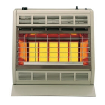
This is an unvented gas-fired heater. It
uses air (oxygen) from the room in which
it is installed. Provisions for adequate com-
bustion and ventilation air must be pro-
vided. Refer to page 4.
WARNING: If not installed, operated and
maintained in accordance with the manu-
facturer's instructions, this product could
expose you to substances in fuel or from
fuel combustion which can cause death or
serious illness.
WATER VAPOR: A BY-PRODUCT OF
UNVENTED ROOM HEATERS
Water vapor is a by-product of gas
combustion. An unvented room heater
produces approximately one (1) ounce
(30ml) of water for every 1,000 BTU's
(.3KW's) of gas input per hour. Refer to
page 4.
Page 1
Advertisement
Table of Contents

Related Manuals for Empire SR-10T-2


Summary of Contents for Empire SR-10T-2
-
Page 1: Installation Instructions
INSTALLATION INSTRUCTIONS OWNER'S MANUAL UNVENTED ROOM HEATER MODELS SR-10T-2 SR-18T-2 SR-30T-2 SR-30T SHOWN WARNING: If the information in EFFECTIVE DATE this manual is not followed exactly, a MARCH, 2000 fire or explosion may result causing property damage, personal injury or This is an unvented gas-fired heater. -
Page 2: Specifications
Specifications Model SR-10T SR-18T SR-30T Input BTU/HR (KW/H) Five Plaques — — 30,000 (8.8) BTU/HR (KW/H) Three Plaques — 18,000 (5.3) — BTU/HR (KW/H) One Plaque 10,000 (2.9) — — Height 22" (559mm) 22" (559mm) 22" (559mm) Width 11 7/8" (302mm) 18"... -
Page 3: Safety Information For Users Of Lp-Gas
SAFETY INFORMATION FOR USERS OF LP-GAS Propane (LP-Gas) is a flammable gas which can cause fires by point with the members of your household. Someday when there may not be a minute to lose, everyone's safety will and explosions. In its natural state, propane is odorless and colorless. - Page 4 Introduction Water Vapor: A By-Product of Unvented Room Heaters Always consult your local Building Department regarding regulations, Water vapor is a by-product of gas combustion. An unvented room codes or ordinances which apply to the installation of an unvented room heater produces approximately one (1) ounce (30ml) of water for every heater.
- Page 5 SR-10T Clearances (Figure 1 and Figure 2) SR-18T Clearances (Figure 3) When facing the front of the appliance the following minimum clearances When facing the front of the appliance the following minimum clearances to combustible construction must be maintained. to combustible construction must be maintained. Left side 6 inches (152mm).
- Page 6 SR-30T Clearances (Figure 4) 11 13/16" (300mm) When facing the front of the appliance the following minimum clearances to combustible construction must be maintained. 7 13/16" (198mm) 1 3/32" Left side 8 inches (203mm). Right side 8 inches (203mm). 2" 2"...
- Page 7 24 1/8" (613mm) 20 1/8" 2" 2" (511mm) (51) (51) 1 3/32" (28mm) 18 7/8" 22" (479mm) (559mm) 4 1/32 2 1/32" (52mm) (102mm) 2" (51mm) MIN SR-30T SHOWN Figure 8 Figure 7 (SR-30T) Installation on Rugs and Tile If this appliance is installed directly on carpeting, tile or other combus- On Solid Wall tible material, other than wood flooring, the appliance shall be installed 1.
- Page 8 Compounds used on threaded joints of gas piping shall be resistant to the A test gage connection is located downstream of the gas appliance action of liquefied petroleum gases. The gas lines must be checked for pressure regulator for measuring gas pressure. The connection is a 1/8 leaks by the installer.
- Page 9 9. Remove heater from wall. 10. Remove gas valve bracket from casing assembly (4 screws to be removed are located on casing assembly back). 11. Remove hydraulic thermostat bulb from thermostat bulb clip located at casing assembly bottom. 12. Remove gas valve from gas valve bracket. 13.
- Page 10 Warning: Service Notes Never use needles, wires, or similar cylindrical objects to clean the pilot to avoid damaging the calibrated ruby that controls the gas flow. Thermostat Operation To ignite main burner, turn gas control knob counterclockwise toward HI setting. To shut down main burner, turn gas control knob clockwise toward LO setting.
-
Page 11: For Your Safety Read Before Lighting
FOR YOUR SAFETY READ BEFORE LIGHTING WARNING: If you do not follow these instructions exactly, a fire or explosion may result causing property damage, personal injury or loss of life. A. This appliance has a pilot which must be lighted by •... - Page 12 R-5008 IGNITOR WIRE R-2314 ORIFICE HOLDER NOT SHOWN SR-216 HARDWARE PACKAGE USE ONLY MANUFACTURED REPLACEMENT PARTS. USE OF ANY OTHER PARTS COULD CAUSE INJURY OR DEATH. Empire Comfort Systems, Inc. Nine Eighteen Freeburg Ave. Belleville, IL 62222-0529 Page 12 R-5210...
- Page 13 SR-30T SR-18T PLEASE NOTE: When ordering parts, it is very important that part number and description of part coincide. INDEX PART INDEX PART NUMBER NUMBER DESCRIPTION NUMBER NUMBER DESCRIPTION 10811 CASING SIDE ASSEMBLY - LEFT 10811 CASING SIDE ASSEMBLY - LEFT SR-090 CASING BACK SR-041...
- Page 14 SR-10T Page 14 R-5210...
- Page 15 SR-18T R-5210 Page 15...
- Page 16 SR-30T Page 16 R-5210...
- Page 17 OPTIONAL BLOWERS SRB-18T and SRB-30T for Unvented Room Heaters SR-18T and SR-30T INSTALLING OPTIONAL BLOWER SRB-18T OR SRB-30T 12. With the heater standing upright, position the air discharge opening If heater is installed onto the wall, in order to install the optional of the blower housing downward.
- Page 18 Wiring The appliance, when installed, must be electrically grounded in accor- dance with local codes or, in the absence of local codes, with the National Electrical Code, ANSI/NFPA 70, if an external electrical source is utilized This appliance is equipped with a three-prong [grounding] plug for your protection against shock hazard and should be plugged directly into a properly grounded three-prong receptacle.
Need help?
Do you have a question about the SR-10T-2 and is the answer not in the manual?
Questions and answers