
Related Manuals for Varec 2500

Summary of Contents for Varec 2500
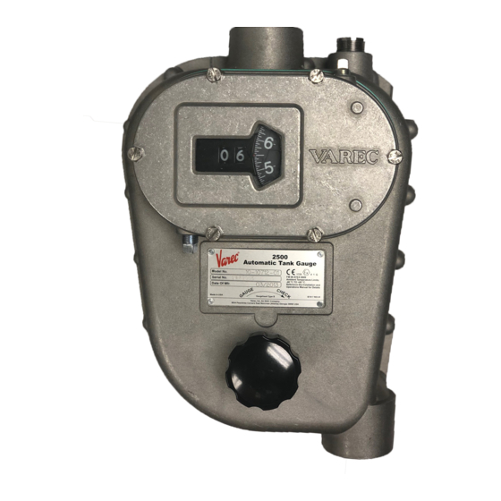
- Page 1 IOM001GVAE1117 2500 Automatic Tank Gauge Mechanically operated, float and tape gauges for continuous liquid-level measurement in bulk storage tanks Automation Solutions for oil & gas, defense and aviation applications...
- Page 3 Phone: (770) 447-9202 Fax: (770) 662-8939 Trademarks Acknowledged Varec, Inc. recognizes all other trademarks. Trademarks of other products mentioned in this manual are held by the companies producing them. FuelsManager®, TankView®, TacFuels®, Varec®, and FuelsManager IntoPlane® are registered trademarks of Varec, Inc.
- Page 4 In no event shall Varec, Inc. or its suppliers be liable for any damages whatsoever including direct, indirect, incidental, consequential, loss of business profits or special damages, even if Varec, Inc. or its suppliers have been advised of the possibility of such damages.
- Page 5 Read this manual carefully and make sure you understand its contents before using this product. Follow all instructions and safety guidelines presented in this manual when using this product. If the user does not follow these instructions properly, Varec cannot guarantee the safety of the system.
- Page 6 Installation and Operations Manual...
-
Page 7: Table Of Contents
Using this Manual ............1 Getting Acquainted with the 2500 Automatic Tank Gauge Systems ....2 Tank Gauge Operation . - Page 8 2500 Automatic Tank Gauge Connecting the Cable to a Float in a Floatwell ........31 Connecting the Cable to a Floating Pan .
- Page 9 2500 Cast Iron Gaugehead Spare Parts ........
- Page 10 2500 Automatic Tank Gauge Installation and Operation Manual...
-
Page 11: Introduction
This manual is designed to assist the user in the installation, operation, maintenance, and troubleshooting of low-pressure 2500 Automatic Tank Gauges. Former 2600 Series gauges with a hand crank are included. These gauges are for use at atmospheric pressure or at low pressure (2.5 psig). -
Page 12: Getting Acquainted With The 2500 Automatic Tank Gauge Systems
2500 Automatic Tank Gauge Getting Acquainted with the 2500 Automatic Tank Gauge Systems The 2500 series of Automatic Tank Gauges (ATG) are float and tape operated instruments designed to provide continuous liquid-level measurement in bulk storage applications. The gauge can be installed on the tank roof or at... -
Page 13: Tank Gauge Operation
Introduction Tank Gauge Operation The 2500 ATG uses a large, stainless steel float attached to a stainless steel perforated tape to Mechanical Counter Sprocket detect the liquid level. The float follows the liquid Wheel level as it rises and falls due to the tension provided by a powerful negator spring or cartridge motor. -
Page 14: System Integration
When a tank gauge transmitter is used, communications and power are required at the gaugehead. Varec transmitters do not require an adaptor flange. When connecting third-party equipment, a specific adaptor flange, depending on the transmitter, is often required. -
Page 15: Check Knob
Introduction Check Knob An operation checker, provided as a standard feature on both the 2500 and 2520 ATG, permits your technician to check the instrument for correct operation. Negator Cassette The negator cassette improves the performance of your mechanical tank gauge by self-aligning the tape and motor as it provides the constant pullback tension required for the float to follow the liquid level. - Page 16 2500 Automatic Tank Gauge Installation and Operations Manual...
-
Page 17: General Preparation
General Preparation Safety Precautions Before installing your 2500 ATG, read and review the see the “Safety Precautions” section of the preface to this document. Continuing with the installation according to the instructions in this manual presumes you have reviewed these safety precautions. -
Page 18: Guidelines, Recommendations, And Options When Preparing For Installation
Note An internal floating roof is often referred to as a “Pan”, e.g. a cone roof tank with a pan and floatwell. Varec offers a kit with a weight that sits on top of the floating roof rather than attaching directly to the roof. This protects the tape or cable from breaking. -
Page 19: Support Brackets
(Part #AA1025). A weight can be used as an alternative when the installation is performed while the tank is in service (Part #BA4481). Varec top guide wire anchors can be screwed or welded into the tank roof, maintenance hatch, or manhole cover. -
Page 20: Tank Roof Entry Via Manhole & Inspection Covers
2500 Automatic Tank Gauge Conduit Elbows Conduit elbows reduce friction and wear on the tape and provide various installation options, depending on the tank type. Varec can provide various angles, materials, and low/high pressure options. Conduit Oil Seals (Optional) Oil seals designed into the conduit pipework... -
Page 21: Floats
If agitators will cause excess float disturbances, contact Varec before proceeding with installation. The 2500 ATG is provided with a standard 14.5” (368 mm) float diameter (with 17” (432 mm) guides) Type 316 stainless steel hollow shell float. -
Page 22: Bolted Tank
2500 Automatic Tank Gauge Installation Steps Checklist When installing a 2500 ATG system on a cone roof tank, complete each installation step below. Check off a step when it is complete. Refer to “Installation Schematics” on page 21 for overall dimensions. -
Page 23: Cone Roof Tank With Internal (Floating Roof) Pan And Floatwell
Roof Pan and Floatwell Installation Checklist When installing a 2500 ATG system on a Cone Roof Tank with Internal (Floating Roof) Pan and Floatwell, complete each installation step below. Check off a step when it is complete. Refer to “Installation Schematics” on page 21 for overall dimensions. -
Page 24: Cone Roof Tank And Internal (Floating Roof) Pan: No Floatwell
Pan: No Floatwell Installation Installation Checklist When installing a 2500 ATG system on a Cone Roof Tank and Internal (Floating Roof) Pan without a Floatwell, complete each installation step below. Check off a step when it is complete. Refer to “Installation Schematics” on page 21 for overall dimensions. -
Page 25: Tank Top Mounting
Tank Top Mounting Installation Checklist When installing a 2500 ATG system on a cone roof tank, complete each installation step below. Check off a step when it is complete. Refer to Section “Installation Schematics” on page 21 for overall dimensions. -
Page 26: Stilling Well Service Cone Roof Tank 6" Diameter Float
Diameter Float Installation Checklist When installing a 2500 ATG system on a Stilling Well Service Cone Roof Tank 6" Diameter Float, complete each installation step below. Check off a step when it is complete. Refer to Section “Installation Schematics” on page 21 for overall dimensions. -
Page 27: External Floating Roof Tank And Floatwell
External Floating Roof Tank and Floatwell Installation Checklist When installing a 2500 ATG system on a External Floating Roof Tank and Floatwell, complete each installation step below. Check off a step when it is complete. Refer to Section “Installation Schematics” on page 21 for overall dimensions. -
Page 28: External Floating Roof Tank: No Floatwell
External Floating Roof Tank: No Floatwell Installation Checklist When installing a 2500 ATG system on a cone roof tank, complete each installation step below. Check off a step when it is complete. Refer to Section “Installation Schematics” on page 21 for overall dimensions. -
Page 29: Interface Service
Figure 13: Interface Service Installation Checklist When installing a 2500 ATG system on a cone roof tank, complete each installation step below. Check off a step when it is complete. Refer to Section “Installation Schematics” on page 21 for overall dimensions. - Page 30 2500 Automatic Tank Gauge Step Description Complete Section “Initial Lubrication” on page 42 Section “Install a Transmitter and Replace all Covers” on page 42 Section “Initial Operation” on page 43 Table 10: Interface Service — Installation Checklist Installation and Operations Manual...
-
Page 31: Installation
This chapter gives instructions for the various types of installations based on the order code options for the 2500 ATG. Note Before installing your 2500 ATG, read and review all see the “Safety Precautions” section of the preface to this document. Continuing with installation according to the instructions in this manual presumes you have reviewed these safety precautions. - Page 32 2500 Automatic Tank Gauge 1-1/2 Inch NPT union 1-1/2 Inch pipe and fittings Note Installation hatch not shown. recommended furnished by customer Varec recommends installing 4.50 a installation hatch. [114] 4.50 [114 ] 24.00 [610] 1-1/2 inch NPT coupling Suggested...
-
Page 33: Tank Roof Entry - Cone Roof Tank
Note Ensure you have completed all previous steps from your installation checklist before proceeding. Note Varec recommends the installation of a manhole cover as shown in Figure 1 on page 46 1. Determine the position on the tank roof beneath which the center of the float will rise and fall (Measuring Point). -
Page 34: Tank Roof Entry - Internal Pan (Floating Roof)
Use a covered floatwell for the best measurement accuracy. 2. Determine the center point of the float well. Varec recommends this position is located a minimum of 16.00 inches (406 mm) and a maximum of 36.00 inches (916 mm) from the wall of the tank. -
Page 35: Tank Roof Entry - Stilling Well
1. Determine the position of the center point at which the float will rise and fall (center point of the floatwell or point on the pan where the cable will attach). Varec recommends this position is located a minimum of 16 inches (406 mm) and a maximum of 36 inches (916 mm) from the wall of the tank. - Page 36 2500 Automatic Tank Gauge Cable locking nut Fixed nut Tension Adjusting nut Gasket BAG LOOSE PARTS FOR SHIPMENT 1-1/4 Inch NPT Back-up plate assembly T.O.E. nipple by Varec For Carbon Steel and Stainless Steel Installation For Alloy20 Installation Figure 5: Detail A - Top Anchors 3.
-
Page 37: Installing Support Brackets & Pipework
3. Install the other elbow on the horizontal pipe. 4. Mount the exterior vertical pipe into the support brackets and screw it into the upper elbow. 5. Tighten the support bracket nuts. 6. Remove the bolts, covers, and gaskets from the elbows. Varec, Inc. -
Page 38: Installing A Gauge Head At Grade Level
2500 Automatic Tank Gauge .25[6.4] X 1.5[38] Steel flat bar 4.50 [114] 4.50 72.00 [114] Tape / cable splice [1829] 1/2-13 Hardware at empty tank position 47.75 [1213] 2 Places 1-1/2 Inch pipe and fittings by customer 2[51] X 2[51] X .25[6.4]... -
Page 39: Installing A Roof Reading Gauge Head
If the negator motor spring is broken, the broken pieces may cause injury when the cover is removed. 1. Remove the back cover and gasket from the gauge head. 2. Apply pipe thread compound and attach the gauge head to the exterior vertical pipe. Position it for convenient reading. Varec, Inc. -
Page 40: Float Installation On An Out-Of-Service Tank
2500 Automatic Tank Gauge Float installation on an Out-of-Service Tank Note Be sure to read Chapter before proceeding with this installation. Ensure you have completed all previous steps from your installation checklist before proceeding. Cone Roof Tank From inside the tank, tilt the float on edge and slip the guide cables through the loops. -
Page 41: Connecting The Cable To A Float In A Floatwell
Connecting the Cable to a Float in a Floatwell Note Ensure you have completed all previous steps from your installation checklist before proceeding. Note On (internal or external) floating pan installations one end of the tape is connected to a cable. Varec, Inc. - Page 42 Consider Figure 12 and apply it to your par- ticular installation or call Varec Help desk with questions. At least 12”...
-
Page 43: Connecting The Cable To A Floating Pan
Tearing or snapping of the tape/cable could result in damage to the gauge head. 1. If there is no floatwell in the floating roof and no other alternative is available, Varec rec- ommends attaching the tape/cable to an object that is resting (unconnected) on the float- ing roof. -
Page 44: Feeding The Tape To A Gauge Head Located At Grade Level
6. To install the perforated tape in the gauge head, proceed to the section for your type of gauge head: For a Standard 2500 ATG with a Negator Spring Motor, go to “With a Negator • Spring Motor” on page 36. -
Page 45: Install Tape In The Gauge Head
8 Negator Spring Motor Screw 9 Tape Sheave Pinor Screw Tape entry for Top-Mounted Gauge Tape entry for Side-Mounted Gauge Standard Gaugehead Negator Cassette Gaugehead (with negator spring motor) (shown with negator cassette removed for tape installation) Figure 14: Tape Routing Varec, Inc. -
Page 46: With A Negator Spring Motor
With a Negator Spring Motor 1. If you have a Standard 2500 ATG with a Negator Spring Motor, follow the procedure in this section to install the gauge tape and load the negator motor on the gauge head. -
Page 47: With A Negator Cassette
With a Negator Cassette If you have a 2500 ATG with Negator Cassette, follow the procedure in this section to install the gauge tape and load the negator cassette on the gauge head. 1. Install the furnished crank assembly and lock it into the case keyhole slot using the spring- loaded screw. -
Page 48: With A Hand Crank Gauge Head
2500 Automatic Tank Gauge Innage Tank Innage Tank Level Outage Tank Outage Tank Level Number of Turns Level (ft) Level (ft) (Neg. Cassette) 12.2 12.8 13.4 14.0 14.6 15.2 15.8 16.5 17.1 17.7 18.3 18.9 19.5 20.1 Table 2: Innage and Outage Turns of the Negator Cassette (continued) 5. -
Page 49: Trimming The Cable At The Float In A Floatwell
Caution Splice must reside in vertical pipe throughout the total travel of the roof. If splice enters gauge head, gauge will hang up and damage will result. If splice passes over elbow sheave, the gauge may hang up or may cause the tape/tape cable to become dis- lodged from the sheave. Varec, Inc. -
Page 50: Reset The Counter
Assembly," in the Service Manual. Figure 15: 2500 ATG Counter Cover and Assembly Parts Note Reversible dials - English gauge heads are shipped with a dial indicating in feet, inches, and 1/16 inch. The backside of the dial is marked to indicate 1/10 ft. x 1/100 foot. -
Page 51: Calibrate The Counter
4. Observe the operation of the counter drums and dial, while slowly cranking the float to the top of the tank and then lowering it to the bottom. The counter drums and dial should rotate freely and return to the calibrated indication when the float touches the tank bot- tom. Varec, Inc. -
Page 52: Initial Lubrication
3. If the gauge head is to be filled with oil, reassemble the gauge head, then fill with oil. For most service, Varec recommends filling the gauge head with oil to reduce wear and pro- long the service life. -
Page 53: Initial Operation
2. When a transmitter or other auxiliary equipment is to be installed, ensure the equipment hole size and bolt pattern matches the 2500 ATG. Remove and discard the cap and red fiber washers from the back cover. Each transmitter’s slotted coupling should properly engage the sprocket sheave auxiliary drive pin. - Page 54 2500 Automatic Tank Gauge 1. Station an observer at the gauge head. 2. Begin filling the tank to raise the float several feet (about three feet or one meter) from the bottom. Caution Do not release the checker knob and allow the springs to return the mecha- nism.
-
Page 55: In-Service Installation Procedures
Chapter 4 In-Service Installation Procedures Note Before installing your 2500 ATG, read and review all safety precautions on page ii of the preface to this document. Continuing with installation according to the instructions in this manual presumes you have reviewed these safety precautions. -
Page 56: Negator Cassette Installation
Pipe Support Structure. Detail “A” shows in-service bottom anchor. Negator Cassette Installation Varec's negator cassette is a fully enclosed design to safely contain a damaged or failed negator motor. It will extend negator motor life by keeping pipe scale and debris off the negator motor. -
Page 57: Assembly
Note In the next step, the alignment of the sprocket sheave to the tape storage sheave is critical for proper operation of the gauge. 2. Adjust the number of shims to bring the sheaves into the specified alignment as shown on Figure 2. Varec, Inc. - Page 58 2500 Automatic Tank Gauge 0.005” to 0.010” Axial play 0.032” Figure 2: Sheave Alignment 3. Complete the installation of the storage sheave by installing shims , a Teflon washer if (45) needed , and a flat washer (44) 4. Test that the sheave turns freely with axial play within 0.005" to 0.010". Lateral offset between the two sheaves should not exceed 0.032".
-
Page 59: Oil Seal Installation
For tank configurations that include optional oil seal accessories, refer to these illustrations and perform the installation procedures included in this section. For most installation, use a low-pour-point, food grade, water-white, mineral oil. Examples are provided in section , Lubrication, on page 71. Varec, Inc. -
Page 60: 27-Inch Water Column Operating Pressure Oil Seal
2500 Automatic Tank Gauge 27-inch Water column operating pressure oil seal ITEM DESCRIPTION 180° Elbow Pipe, 1-1/2 inch NPT X 38 [965] long Pipe, 1-1/2 inch NPT X 32 [813] long 180° Elbow with drain 10.50 [267] 6.00 [152] 1-1/2 Inch NPT 90°... -
Page 61: 8.5-Inch Water Column Operating Pressure Oil Seal
7. Proceed with the remainder of the tank installation to the paragraph Initial Lubrication, then fill the oil seal as follows: a. Remove the cover from 90 degree elbow. b. Fill to halfway in the short pipe. Note To drain the oil, open the plug in 135 degree elbow Varec, Inc. -
Page 62: Inspection Hatch And Manhole Cover
2500 Automatic Tank Gauge Inspection Hatch and Manhole Cover Varec recommends the installation of a manhole or inspection hatch, if there is not already one located within arm’s reach of the tape pipe location. Inspection Hatch 1. Remove the cover to a safe welding location. -
Page 63: Guide Wire Bottom Anchors
Manhole Cover and Inspection Hatch Guide Wire Bottom Anchors Varec supplies an anchor bar for in-service installations (Part Number BA4481) that must be ordered separately. It is for normal service only. The guide cables fasten to the anchor bar with cable clamps (see Figure 6). - Page 64 2500 Automatic Tank Gauge 5. Tighten the adjustment nut until the guide cable is tensioned by the spring. Trim excess cable. 6. Use pipe thread compound and install top anchor nipples and cap. Warning Whenever the back cover of the gauge head is removed, stand to one side as the last bolt is removed.
- Page 65 Note To fill the counter assembly side of the gauge head with oil, it is necessary to change the bottom NPT condensate drain plug. Replace it with a solid 1/4”-NPT plug or reverse the top solid plug with the bottom plug. Fill the hole in the condensate drain plug with RTV 737 sealant. Varec, Inc.
- Page 66 2500 Automatic Tank Gauge Installation and Operations Manual...
-
Page 67: Operation
3. Turn the crank counter-clockwise to raise the float about 2 inches (51 mm) above the prod- uct, then lower it back to the surface. The float should not be left on the surface of prod- ucts that are agitated. Raise it to the tank top in this situation, and latch the ratchet pawl. Varec, Inc. - Page 68 2500 Automatic Tank Gauge Installation and Operations Manual...
-
Page 69: Gauge Head Disassembly And Re-Assembly
Figure 8 is key to understanding the disassembly/reassembly procedure. The small numbers in parentheses (for example, ), refer to the item numbers in this figure. References in the (12) following procedures are directed to this figure, unless otherwise indicated. Varec, Inc. - Page 70 2500 Automatic Tank Gauge for Cassette Figure 8: 2500 ATG (Type C) Gauge Head Spare Parts Perform these steps to disassemble the gauge head. Note Disassemble the gauge head only as far as needed to replace worn or defective parts.
- Page 71 If you remove the gauge head, secure the end of the tape so it cannot retract up into the conduit. Use care to not kink or bend the tape. 13. You can now remove the gauge head from the conduit and complete the rest of this disas- sembly at the workbench. Varec, Inc.
- Page 72 2500 Automatic Tank Gauge Caution Do not release crank handle (7) when negator spring motor is being loaded and thumbscrew lock is removed. Item Description 1 Sprocket Sheave 2 Tape Storage Sheave 3 ThumbScrew Lock 4 Tape Keeper 5 Motor Storage Sheave...
- Page 73 The gauge check knob shaft Teflon o-ring (26) on the inside of the gauge head is pressed into place with a special setting tool. If replacement is required, call Varec for mainte- nance. 30. Remove Teflon o-ring only if gauge head showed signs of leakage.
-
Page 74: Gauge Head Assembly
2500 Automatic Tank Gauge Gauge Head Assembly Unless otherwise labeled, numbers in parentheses, for example, refer to the item callout (12) numbers on Figure 8 or Figure 9. Perform the following steps to reassemble the gauge head. When white silicon grease is called for, use Dow Corning®... - Page 75 (45) 34. Test that the sheave turns freely with less than 0.005” axial play for the Standard 2500 ATG and no axial play for models with crank or cassette. 35. Secure the motor storage sheave assembly with retaining ring .
-
Page 76: Counter Wheel Assembly
2500 Automatic Tank Gauge Counter Wheel Assembly If you remove the screws and retainer from the counter wheel assembly and the pinion (43) (21) gear is disengaged, you must remove the dial and pinion gear in order to reset the counter... -
Page 77: Counter Bearing Adjustment Procedure
Loosen the Tape Storage Sheave on the inside of the gauge and drive the bearing outward using a punch and hammer approximately 1/16" and recheck the depth. This adjustment requires a full disassembly of the gauge. Varec, Inc. - Page 78 2500 Automatic Tank Gauge COUNTER SPROCKET SHEAVE If there is play between the Bearing Depth Gauge, the counter boss, and the dial plate hub, tap the dial plate hub with a hammer with the Bearing Depth Gauge in place. When the dial plate hub is flush against the Bearing Depth Gauge, the counter bearing is adjusted correctly.
-
Page 79: Maintenance Routines
Chapter 7 Maintenance Routines Varec recommends a regular schedule of maintenance for the 2500 Automatic Tank Gauge (ATG), outlined in the table below. Actual frequency of inspections and maintenance may vary depending on the specific environmental conditions and operation at your site—even from tank to tank. -
Page 80: Operation Check
2500 Automatic Tank Gauge Operation Check Check the operation of the gauge by rotating the gauge check knob on the front of the gauge. The dial should show the movement of the float when the check knob is rotated. Caution Do not release the gauge check knob and allow the springs to return the mechanism. -
Page 81: Lubrication
Fill the hole in the condensate drain plug with Dow Corning® RTV 737 sealant. The counter assembly will hold approximately 1.06 quarts (1.0 liter). The appropriate oil selected for lubrication may also be used in conduit oil seal units. Varec, Inc. -
Page 82: Corrosion Check
Subsequent inspections should be made every 90 days. The user may adjust the schedule for his own convenience and safety, depending upon the product. Varec maintenance service contracts are available. Please consult a sales or service representative for further details. Installation and Operations Manual... -
Page 83: Spare Parts And Maintenance Kits
Chapter 8 Spare Parts and Maintenance Kits Varec can supply individual spare parts for the 2500 ATG, maintenance kits, and installation accessories. The following kits are specifically designed to assist with a regular schedule of maintenance and to improve the quality and performance of your 2500 ATG. This chapter details the contents of each kit and provides an illustration to assist in locating the part within the assembly. - Page 84 2500 Automatic Tank Gauge Item Part Description BA7761 Tape Storage Sheave Assembly (Includes item57) BA9796 Crank Tape Storage Sheave 06-10364 Tape Storage Sheave Assembly - Cassette B8234-001 Dial Retainer B7693-005 Shaft (2) - Gauge Head Type B BA7763 Shaft Support Assembly - Gauge Head Type C and Cast Iron (2)
- Page 85 Pinion - Crank B9304-005 Pawl Spacer - Crank B9750-005 Spring Support Guide - Crank B9302-001 Crank Direction Label B9797-005 Crank Ratchet Spring B10938-011 Ratchet Gear - Crank B10939-011 Pawl, Ratchet - Crank D6360-011 Crank Handle B10147-005 Crank Shaft Varec, Inc.
- Page 86 Bolt for Crank Knob 02-013223 PTFE Shim for checker Table 3: 2500 ATG Gauge Head Spare Parts List Cartridge Crank Handles as provisioned as follows: Handle 06-10490 fits all gauges in which the tape storage sheave has ball bearings, which includes all cassette gauges, Type B with standard motors dated 2008 and later, and all Type C gauges.
- Page 87 Note Use washers 45 as required. Not shown:49, 51, 59 * 48 includes parts 55(x2) & 56. * 8 includes parts 55(x2), 57, & 58. Figure 11: 2500 ATG Gauge Head (Type B) with Negator Motor Spare Parts Diagram Varec, Inc.
- Page 88 2500 Automatic Tank Gauge Figure 12: 2500 ATG Gauge Head (Type B) with Negator Cassette Spare Parts Diagram Installation and Operations Manual...
- Page 89 Figure 13: 2500 ATG Gauge Head (Type C) with Negator Motor and Negator Cassette Spare Parts Dia- gram Varec, Inc.
- Page 90 2500 Automatic Tank Gauge Figure 14: 2500 ATG Gauge Head with Hand Crank Installation and Operations Manual...
-
Page 91: 2500 Cast Iron Gaugehead Spare Parts
2500 Cast Iron Gaugehead Spare Parts Figure 15: 2500 Cast Iron Gaugehead Item Part Description B4396-046 Back Cover Gasket (Type A Gaugeheads prior to 1983, and Low Pressure Iron Gaugeheads) Varec, Inc. - Page 92 2500 Automatic Tank Gauge Item Part Description B5059-046 Back Cover Cap Gasket (For a transmitter) B5059-146 Back Cover Cap Gasket - No center hole (if no transmitter) 03ci B5060-001-7 Back Cover Cap, Painted (Cast Iron Gaugehead) B7415-093 Teflon Washer (Not shown - used on older Gaugeheads)
- Page 93 B7790-005 Check Pawl B7795-005 Hair Pin Spring P10-54 Retaining Ring for Counter Gland (Cast Iron Gaugeheads) B14057-001-7 Gauge Check Seal Plate (Cast Iron Gaugeheads) P31-1113 Seal Plate Screws (Cast Iron Gaugeheads) BE18440 Counter Gland Assy (Cast Iron Gaugeheads) Varec, Inc.
-
Page 94: Basic Maintenance Kit
2500 Automatic Tank Gauge Basic Maintenance Kit The Basic Maintenance Kit provides all the parts required for basic maintenance on the 2500 ATG. Depending on your selection, you will receive the metric or imperial parts required. Part No. Description 13-08766... -
Page 95: Extended Maintenance Kit
Extended Maintenance Kit The Extended Maintenance Kit provides all the parts required for extended maintenance on the 2500 ATG Gauge Head. Depending on your selection, you will receive the metric or imperial parts required, listed in Table . Part No. - Page 96 2500 Automatic Tank Gauge Item Part No. Description Quantity in Kits B4396-046 Back Cover Gasket 2500A (Prior to 1983) 02-04490-071 Back Cover Gasket 2500B (1983 - 2012) 02-013127-046 Back Cover Gasket 2500C (2013 and later) B7415-093 Teflon Washer B8235-040 Imperial Dial Gear...
-
Page 97: Additional Items
Hex Head Cap Screw A370-006 Elbow Yoke Table 5: Extended Maintenance Kit Parts List Additional items When performing extended maintenance, Varec also recommends replacing the tape or the tape-and-cable combination as shown in the following table. Item Part No. Description... -
Page 98: Overhaul/Refurbishing Kit
2500 ATG (Type C Gauge Head Shown) Extended Maintenance Kit Parts Diagram Overhaul/Refurbishing Kit The Refurbish/Overhaul Kit provides all the parts required for overhaul maintenance on the 2500 ATG. Depending on your selection, you will receive the metric or imperial parts required, listed in Table 18 Installation and Operations Manual... - Page 99 Binding Head Mach. Screw P10-29 Grip ring P13-20 Bushing 02-08543 Washer B4847-005 Washer P031-05-1721 Hex Head Cap Screw P031-05-1871 Hex Head Cap Screw P031-01-1719 Binding Head Mach. Screw P31-612 Hex socket set screw, Cup Pt. P031-08-1720 Counter Screw Varec, Inc.
- Page 100 2500 Automatic Tank Gauge Item Part No. Description Quantity in Kits P31-1 Washer P31-13 Shim Washer BA7762 Negator Motor Assembly (includes items 55x2 & 56) 06-10490 Crank Handle (Not Shown) 02-09598 Shoulder Bushing B14872-101 Motor Top Plate P31-671 Screw P31-692...
- Page 101 EE or FF AA & CC Float Grounding Kit Sheave Elbow Cover, Top Guidewire Anchor Gasket and Bolt Tape Clamp Assembly Example Cone Roof Installation Figure 19: 2500 ATG (Type C Gauge Head Shown) Overhaul Maintenance Kit Parts Diagram Varec, Inc.
-
Page 102: Additional Items
2500 Automatic Tank Gauge Additional items When performing a complete overhaul or refurbish, Varec recommends replacement of the tape (or tape and cable combination), anchors, and guide wires as shown in the following table. Item Part No. Description BM5478-600 Tape Clamp Assembly... -
Page 103: Negator Cassette And Negator Cassette Kit
2500 ATG (Type C Gauge Head Shown) Shoulder Bushing Retrofit Kit Parts Diagram Negator Cassette and Negator Cassette Kit The Negator Cassette Kit (item 68) provides the parts required to convert a 2500 ATG fitted with a negator motor to a gauge head with a negator cassette. - Page 104 * from a standard gaugehead Note Use items 44 and 45 as required Negator Cassette Gaugehead Figure 21: 2500 ATG (Type B Gauge Head Shown) Negator Cassette Conversion Kit Parts Diagram (Item 68) Installation and Operations Manual...
-
Page 105: Float Grounding Kit
The calibrator is accessed by removing the counter assembly cover. By simply turning the calibrator, the counter and the transmitter can both be set to the proper level. The dual calibrator can be retrofitted to existing 2500 ATG installations (Part #13-08948). Figure 23: Gauge Calibrator Assembly... -
Page 106: Condensate Reservoir
Figure 24: Condensate Reservoir Shock Absorber The Shock Absorber reduces wear and maintenance on a 2500 ATG by minimizing the transfer of wave energy from the float to the perforated tape and gauge head components. It prevents the float from becoming... - Page 107 Alum-Metric w/Crank BM18910-110EXT Alum-Metric w/Crank, Extended Range 10-10712-01OUT Gauge Assembly, 2500 English w/Negator Cassette - Outage 10-10712-02OUT Gauge Assembly, 2500 Metric w/Negator Cassette - Outage Table 11: Part Numbers for Complete 2500 ATG Gauge Heads Spare Parts List Varec, Inc.
- Page 108 2500 Automatic Tank Gauge Installation and Operations Manual...
-
Page 109: Troubleshooting
Troubleshooting Friction is a common problem that affects gauge accuracy. Some liquids produce corrosion in the mechanism. Periodic inspection and maintenance provided by a Varec service contract can prevent problems from occurring. Periodic cleaning, lubrication, and replacement of worn parts stops trouble before it starts. -
Page 110: Calibration Repeatability Unstable
2500 Automatic Tank Gauge Possible Cause Action Dials stopped? Yes - • Check for frozen tape sprocket sheave shaft. Repair/ replace. • Check for frozen accessory shaft. Repair/replace. • Check dial gear engagement with pinion gear. Adjust/ replace. • Check gauge checker for broken spring and damaged ratchet pawl. - Page 111 • Tighten, repair or replace. No - • Go to 6. Worn Teflon bushings or bearings? Yes - • Refurbish gauge, replace Teflon bushings or bearings. • Special tools may be required. Table 13: Broken Negator Spring - Possible Cause/ Action Varec, Inc.
- Page 112 2500 Automatic Tank Gauge Installation and Operations Manual...
-
Page 113: Specifications And Reference Data
- Basic method and requirements”. The instrument described in this manual thus complies with the statutory requirements of the EC directives. Varec confirms the successful testing of the instrument by affixing to it the CE mark. -
Page 114: 2500 Atg Product Dimensions
2500 Automatic Tank Gauge 2500 ATG Product Dimensions 3.0" (76 mm) 4.0" 5.8" 0.6" 1/2" NPT 8.5" (101 mm) (147 mm) (15 mm) 5/16"-18x1 (216 mm) 3.5" 1.28" (89 mm) (32 mm) 5.4" 5/16"-18x1.125 (137 mm) 2.0" 13.6" (51 mm) (345 mm) 1-1/2"... -
Page 115: Floats
Figure 29: 2500 Cast Iron Gauge Head Product Dimensions Floats Part # Material Net Weight Size BM9074-000 316 S.S. 8.8 lb (4 kg) 17” (432 mm) Flat BM12339-000 Alloy 20 10.7 lb (4.9 kg) 17” (432 mm) Flat BM12338-000 Monel 10.5 lb (4.8 kg) -
Page 116: Standard Installation Kits
2500 Automatic Tank Gauge 06-08564 90° Elbow Atmospheric Aluminum Delrin 06-07726 90° Elbow Atmospheric Aluminum 316 SS BM4675 90° Elbow Atmospheric Cast iron 316 SS BM5074 90° Elbow Atmospheric 316 Stainless steel 316 SS BM3480 135° Elbow Atmospheric Aluminum Delrin BM3481 180°... -
Page 117: Approvals
N250003 – 2500 Automatic Tank Gauge, Metric, Negator Motor N250004 – 2500 Automatic Tank Gauge, Metric, Float Crank N250005 – 2500 Automatic Tank Gauge, English, Iron Gauge Head N250006 – 2500 Automatic Tank Gauge, Metric, Iron Gauge Head N250011 – 2500 Automatic Tank Gauge, English, Negator Cassette N250013 –... - Page 118 2500 Automatic Tank Gauge Installation and Operations Manual...
-
Page 119: Order Codes
T41 Moderate service cone roof tank T51 Interface service cone roof tank; 15 min. s.g. differential T52 Interface service cone roof tank; 25 min. s.g. differential T55 Stilling well service cone roof tank; 6" dia. float N250001- Complete product designation Varec, Inc. -
Page 120: Aluminum Gauge Head - Metric Configuration - Negator Motor
2500 Automatic Tank Gauge Aluminum Gauge Head – Metric Configuration – Negator Motor Tank Type T11 Standard service cone roof tank T12 Standard service cone roof tank with pan and floatwell T13 Standard service floating roof tank and floatwell T14 Standard service tank top mounting T15 Standard service bolted tank T16 Standard service floating roof tank;... -
Page 121: Iron Gauge Head - English Configuration
T05 Standard service bolted tank T06 Standard service floating roof tank; no floatwell T07 Standard service cone roof tank and pan; no floatwell T41 Moderate service cone roof tank T55 Stilling well service cone roof tank N250011- Complete product designation Varec, Inc. -
Page 122: Aluminum Gauge Head - Metric Configuration - Negator Cassette
2500 Automatic Tank Gauge Aluminum Gauge Head – Metric Configuration – Negator Cassette Tank Type T11 Standard service cone roof tank T12 Standard service cone roof tank with pan and floatwell T13 Standard service floating roof tank and floatwell T14 Standard service tank top mounting T15 Standard service bolted tank T16 Standard service floating roof tank;... - Page 124 © 2014 Varec, Inc. All Rights Reserved. This document is for information purposes only. Varec, Inc. makes no warranties, express or implied, in this summary. The names of actual companies and products mentioned herein may be the trademarks of their respective owners.
Need help?
Do you have a question about the 2500 and is the answer not in the manual?
Questions and answers