Table of Contents
Advertisement
Quick Links
Download this manual
See also:
Instruction Manual
SERVICE MANUAL
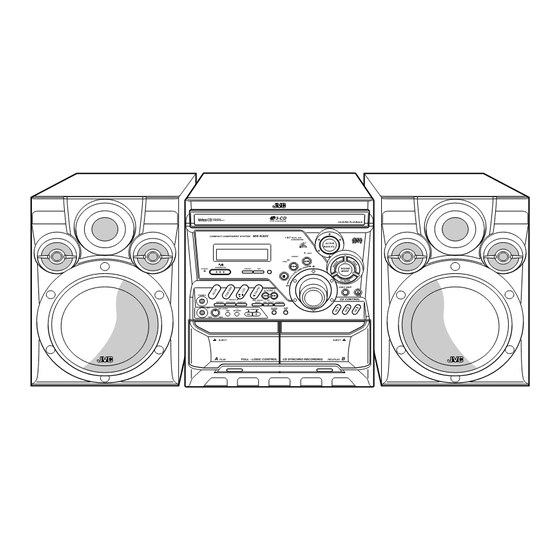
COMPACT COMPONENT SYSTEM
RM-SMXK35V REMOTE CONTROL
1
2
3
STANDBY/ON
4
5
6
SLEEP
7
8
9
AUX
10
+10
FM /AM
FM MODE
CD
1
CD
2
CD
3
CD
SELECT
PROGRAM
REPEAT
TAPE A/B
TAPE
/RANDOM
PREV.
NEXT V.INTRO HIGHLIGHT
RETURN
STILL
ON SCREEN
KARAOKE
KEY CONTROL
MPX
SOUND
MODE
ECHO
ACTIVE
VOLUME
FADE
BASS EX.
MUTING
SP-MXK35V
Contents
Safety precautions
Preventing static electricity
Important for laser products
Disassembly method
Adjustment method
Flow of functional operation
until TOC read
MX-K35V
3-CD
NTSC/PAL
COMPATIBILITY
PLAY & EXCHANGE
MX-K35V
COMPACT COMPONENT SYSTEM
1 BIT
DUAL D/A
CONVERTER
PRESET
PREV
STANDBY/ON
STANDBY
CANCEL
SET
VCD NUMBER
TUNING
PHONES
SELECT
REC START
CD
REPEAT
PROGRAM
RANDOM
/STOP
REC START DUBBING
CLOCK
TAPE
MIC
MIC LEVEL
KEY CONTROL
/TIMER
A/B
PBC
RETURN
MIN
MAX
EJECT
A
PLAY
FULL - LOGIC CONTROL
CD SYNCHRO RECORDING
CA-MXK35V
1-2
1-3
1-4
1-5
1-20
1-22
COPYRIGHT
2001 VICTOR COMPANY OF JAPAN, LTD.
CD-R/RW PLAYBACK
ACTIVE
BASS EX.
NEXT
SOUND
MODE
DISC SKIP
CD CONTROL
EJECT
B
REC/PLAY
SP-MXK35V
US ---------------------- Singapore
UX ------------------- Saudi Arabia
Maintenance of laser pickup
Replacement of laser pickup
Description of major ICs
Wiring connections
MX-K35V
Area suffix
1-23
1-23
1-24
1-35
No.21033
Nov. 2001
Advertisement
Table of Contents

Related Manuals for JVC MX-K35V


Summary of Contents for JVC MX-K35V
- Page 1 MX-K35V SERVICE MANUAL COMPACT COMPONENT SYSTEM MX-K35V 3-CD NTSC/PAL COMPATIBILITY PLAY & EXCHANGE CD-R/RW PLAYBACK RM-SMXK35V REMOTE CONTROL MX-K35V COMPACT COMPONENT SYSTEM 1 BIT DUAL D/A STANDBY/ON CONVERTER ACTIVE BASS EX. SLEEP NEXT PRESET PREV FM /AM FM MODE STANDBY/ON...
- Page 2 MX-K35V 1. This design of this product contains special hardware and many circuits and components specially for safety purposes. For continued protection, no changes should be made to the original design unless authorized in writing by the manufacturer. Replacement parts must be identical to those used in the original circuits. Services should be performed by qualified personnel only.
- Page 3 MX-K35V Preventing static electricity 1. Grounding to prevent damage by static electricity Electrostatic discharge (ESD), which occurs when static electricity stored in the body, fabric, etc. is discharged, can destroy the laser diode in the traverse unit (optical pickup). Take care to prevent this when performing repairs.
- Page 4 MX-K35V Important for laser products 5.CAUTION : If safety switches malfunction, the laser is able 1.CLASS 1 LASER PRODUCT to function. 2.DANGER : Invisible laser radiation when open and inter 6.CAUTION : Use of controls, adjustments or performance of lock failed or defeated. Avoid direct exposure to beam.
-
Page 5: Table Of Contents
MX-K35V Disassembly method Commence disassembly of this set by removing the main units and then proceed to the components and assemblies inside the units. Replacement of the fuses and the power IC Top cover CD changer unit Front panel assembly... -
Page 6: Replacement Of The Fuses And The Power Ic
MX-K35V <Disassembly of the main blocks of this set> Fuse (F953) Replacement of the fuses and the power IC 1.25A 250V Fuse (F951) Replacing the fuses (See Fig.1) 2.5A 250V Prior to performing the following procedure, remove Power transformer the top cover. -
Page 7: Top Cover
MX-K35V Removing the top cover (See Fig.5 and 6) Top cover Remove the two screws C and four screws D that retain the top cover from the rear of the body. Remove the four screws E retain the top cover from the two sides of the body. -
Page 8: Cd Changer Unit
MX-K35V CD tray panel Removing the CD changer unit (See Fig.7 to 10) Prior to performing the following procedures, remove the top cover. [Caution] Although the CD mechanism unit can be removed without removing the CD tray panel, it is still recommended to remove it in order to prevent damage. -
Page 9: Front Panel Assembly
MX-K35V Removing the front panel assembly (See Fig.11 and 12) Prior to performing the following procedures, remove the top cover. Also remove the CD changer unit. Disconnect the parallel wire and card wire from the connectors CN901 and CN903 on the power amplifier board. -
Page 10: Removing The Main Board
MX-K35V <Disassembly of units and assembly Main board inside this set> Removing the main board CN601 (See Fig.13 and 14) Prior to performing the following procedures, remove the top cover. Also remove the CD changer unit. Disconnect the wires from CN602 and CN603 on the main board, which is located on the backside of the CD changer unit. -
Page 11: Removing The Cd Changer Mechanism Assembly
MX-K35V Removing the CD changer mechanism assembly (See Fig.15 to 17) Prior to performing the following procedures, remove the top cover. Also remove the CD changer unit. Remove the spring d from the front surface of the [Note] CD changer mechanism unit. -
Page 12: Removing The Cd Pickup
MX-K35V Removing the CD pickup (See Fig.18) CD pickup Prior to performing the following procedures, remove the top cover. Also remove the CD changer unit. Also remove the CD changer mechanism assembly. Widen the section f. While keeping the section f wide open, push the section g in the direction of the arrow to remove the shaft, and then remove the CD pickup. -
Page 13: Removing The Cassette Deck Mechanism
MX-K35V Front panel Removing the cassette deck mechanism assembly (See Fig.22) Prior to performing the following procedure, remove the top cover. Also remove the CD changer unit. Also remove the front panel assembly. 1.Remove the five screws R retaining the cassette... -
Page 14: Removing The Microphone Amplifier Board
MX-K35V Removing the microphone amplifier board (See Fig.24 and 25) Front panel assembly Prior to performing the following procedure, remove the top cover Also remove the CD changer unit. Also remove the front panel assembly. Pull out the mic volume knob from the front of the front panel assembly. -
Page 15: Removing The Switch Board And Active Bass Ex. Switch Board
MX-K35V Removing the switch board and active bass ex. switch board Front panel assembly (See Fig.26 to 29) Prior to performing the following procedures, remove the top cover. Also remove the CD changer unit. Also remove the front panel assembly. -
Page 16: Removing The Cassette Deck Main Motor, And Replacing The Main Belts
MX-K35V Removing the cassette deck main motor, and replacing the main belts Cassette deck mechanism (Front side) (See Fig.22, 30 and 31) Prior to performing the following procedures, remove the top cover. Also remove the CD changer unit. Also remove the front panel assembly. -
Page 17: Removing The Cassette Deck Heads
MX-K35V Removing the cassette deck heads Cassette deck mechanism (See Fig.22 and 33) (Front side) Prior to performing the following procedures, remove the top cover. Also remove the CD changer unit. PB head REC/PB head Also remove the front panel assembly. -
Page 18: Removing The 3-Pin Regulator
MX-K35V Removing the 3-pin regulator Rear panel (See Fig.2, 37 and 38) Prior to performing the following procedures, remove the top cover. Remove the two screws A connecting the heat sink cover to the rear panel. Pull the heat sink cover foward you. -
Page 19: Removing The Power Amplifier Board, Voltage Selector Board And Power Transformer Board
MX-K35V Removing the power amplifier board, Rear panel voltage selector board and power transformer board (See Fig.2, 3, 37, 39 to 42) Speaker terminal Prior to performing the following procedures, remove the top cover. Also remove the CD changer unit. - Page 20 MX-K35V Adjustment method Measurement instruments required for adjustment Radio input signal 1. Low frequency oscillator, AM modulation frequency : 400Hz This oscillator should have a capacity to output 0dB Modulation factor : 30% to 600ohm at an oscillation frequency of 50Hz-20kHz.
- Page 21 MX-K35V Arrangement of adjusting positions Cassette deck mechanism (Front side) Main board CN308 PB Head REC/PB Head 8-Pin (Deck-A) (Deck-B) L301 FM VT voltage measurement point AM VT voltage Head azimuth screw Head azimuth screw measurement point (Forward side) (Forward side)
- Page 22 MX-K35V Flow of functional operation until TOC read Check Point Slider turns REST Play Key Power ON Confirm that the voltage at the pin1 SW ON. of CN602 is "H"\"L"\"H". Automatic tuning of TE offset Check that the voltage at the...
- Page 23 MX-K35V Replacement of laser pickup Maintenance of laser pickup (1) Cleaning the pick up lens Before you replace the pick up, please try to Turn off the power switch and,disconnect the clean the lens with a alcohol soaked cotton power cord from the AC OUTLET.
- Page 24 MX-K35V Description of major ICs TMP87CM78 (IC701) : System control microprocessor 1. Terminal layout 2. Pin function Pin No. Symbol Function Pin No. Symbol Function + 5 V b a c k u p s u p p l y...
- Page 25 MX-K35V ES3880FL (IC101) : MPEG decoder 1. Terminal layout 2. Block diagram 80 ~ 51 Processor RAS# Interface DA[9:0] LA[17:0] DRAM Interface DBUS[15:0] LD[7:0] DRAM Huffman DOE# LCS3#, LCS#[1:0] Decoder DWE# LWR# 2Kx32 ROM RISC CAS# LOE# Processor 512x32 SRAM...
- Page 26 MX-K35V ES3883F (IC102) : Companion chip 1. Terminal layout 80 ~ 51 1 ~ 30 2. Pin function Pin No. Symbol Function Pin No. Symbol Function Ground Analog VCC, 5V VCCAA No connect 45,46 Right channel output AOR+,AOR- Voltage supply, 5V...
- Page 27 MX-K35V BA15218 / BA15218F (IC102 / IC852) : Dual operational amplifier 1. Terminal layout & block diagram OUT1 1 8 Vcc -IN1 2 7 OUT2 +IN1 3 6 -IN2 5 +IN2 BA3837 (IC103) : MIC Mixer 1. Terminal layout & block diagram 2.
- Page 28 MX-K35V PST9119 (IC703) : Reset IC 1. Terminal layout 2. Block diagram 1 2 3 STK402-070 (IC151) : 2-ch audio power amplifier 1. Terminal layout 2. Block diagram PRE-VCC IN 1 NF 1 SUB G TA2092N (IC603) : Power driver IC for CD 1.
- Page 29 MX-K35V TA2153FN (IC601) : RF amplifier for digital servo 1. Terminal layout 2. Block diagram RFN2 RFAGC GMAD AGCIN GVSW RFGO RFRPIN RFCT RFRP 2VRO SBAD 3. Pin function PIN No. Symbol Function Power supply input terminal RFAGC RF amplitude adjustment control signal input terminal. Controlled by 3-PWM signals. (PWM carrier = 88.2kHz)
- Page 30 MX-K35V TA8189 (IC401) : REC/PB amplifier 1. Terminal layout 2. Block diagram CH1_A CH2_A CH1_B CH2_B CH2_B 14 REC_IN2 CH2_A PREOUT1 PREOUT2 13 ALC MIX_OUT A/B_SW GND1 EQSW 12 GND CH1_A REC_OUT1 REC_OUT2 REC_NF1 REC_NF2 11 REC_IN1 REC_IN1 REC_IN2 CH1_B 3.
- Page 31 MX-K35V TA2104N (IC1) : 1chip AM/FM, MPX tuner system 1. Terminal layout 2. Pin function No. Symbol Function Symbol I/O Function RFGND FM_RFOUT FM_RFIN RFVCC RFGND Ground terminal for RF LPF1/BAND FM/AM switch AM_FIL AM_RFIN FM_RFIN Input of FMRF signal...
- Page 32 MX-K35V TC9462F (IC602) : Digital servo single chip processor 1. Terminal layout 2. Pin function Pin No. Symbol Function Pin No. Symbol Function TEST0 Te s t m o d e t e r m i n a l . N o r m a l l y, k e e p a t o p e n D i g i t a l p o w e r s u p p l y v o l t a g e t e r m i n a l .
- Page 33 MX-K35V Pin No. Symbol Function Pin No. Symbol Function RFGC R F a m p l i t u d e a d j u s t m e n t c o n t r o l s i g n a l o u t p u t TESIN Te s t i n p u t t e r m i n a l .
- Page 34 MX-K35V TDA7440D (IC101) : Audio processor 1. Terminal layout 2. Block diagram MUXO-L IN(L) TRE(L) BIN(L) BOUT(L) LIN1 RIN3 RIN4 100K RIN2 LOUT RIN1 ROUT LIN2 LIN1 AGND 100K LIN2 SPKR ATT LOUT VOLUME TREBLE BASS LEFT LIN3 LIN3 CREF...
- Page 35 MX-K35V Wiring connections Cassette deck main motor Card wire Control/FL board Cassette mechanism Card wire Color codes are shown below. Brown Cassette board CN703 Orange Yellow Green Blue P.B. head bottom side REC/P.B. head bottom side Violet CN702 Gray White...
- Page 36 MX-K35V Block diagrams FM/AM Ant. To Headphone To Mic/Echo Main Power amplifier CN903 JA302 CN306 JA301 JA303 AUX In Line-Out Q151 Mute Deck-A IC151 IC401 IC103 PB-Head Speaker 2CH Power Amp Main output TA8189N TC9257P TA2104N BA3837 Q101 STK402-070 Tape PB/Rec V.Cancel...
- Page 37 MX-K35V MX-K35V Standard schematic diagrams <Main section> Head amplifier, tuner and audio section Head amplifer section Cassette mechanism section (To A-4 on page 2- 4) TO CTRL PWB R303 R370 R304 1000P C509 CN301 TO CD SCH.SECTION TO CD SCH.SECTION...
- Page 38 MX-K35V CD servo control and CD mechanism section CD servo control section CD mechanism section R658 100K C604 C601 0.01 CN606 R610 8.2K R612 FFC-25P C602 16V47 R634 R666 4.7K R609 8.2K V.GND BUS0 R608 8.2K R613 R633 R667 4.7K...
- Page 39 MX-K35V MX-K35V <Front section> Control/FL and switch section FL701 VACUUM FLUORESCENT DISPLAY R789 -35V SMUT SMUT PCNT PCNT SFTY SFTY D704 1SS133 R702 C717 150P R792 CNTT CNTT OPSW D705 1SS133 OPSW R704 R793 CLSW CLSW UPSW UPSW 2.2K R781...
- Page 40 MX-K35V VCD section R1102 Cancel EAUX13 R1101 4.7K C1101 L1106 C1137 10V470 2.7uH J1101 Q1101 V.OUT KTA1504 IC104 27C020 C1130 16V100 L1103 10uH R1124 100K Chassis GND L1104 X1101 C1126 16V47 27.00MHz R1123 4.7K C1127 C1111 R1133 R1135 2.2K DSC_D7...
- Page 41 MX-K35V MX-K35V Main amplifier section R922 2.2K SP-L + R921 470K SP-L - RY901 C924 50V1 SP-R - R926 C151 25V4.7 SP-R + R920 R928 Q918 DTC114YS R924 Q921 C923 25V10 D918 1SS133 R156 KTC3199 IN 2 R923 100K R930 2.2K...
- Page 42 MX-K35V ECHO section Power supply section U/UB/UR/US/UT Version 110/127/220/230-240V 50/60Hz VOL-SEL S999 C871 0.047 IC852 T951 BA15218F Q851 2SD2144 F953 C872 390P T1.25A F952 T1.6A Q852 D851 2SC2785 R866 1SS133 JA851 HTJ-064-07AG F951 T.2.5A AC-PLUG C877 +B 9V 50V4.7 R873...
- Page 43 MX-K35V MX-K35V Printed circuit boards Note : This is a printed circuit board on a silk screen print. Main board This method enables the patterns of both surfaces of the printed circuit board to be shown because of the transparency of the silk screen print.
- Page 44 MX-K35V Front board Note : This is a printed circuit board on a silk screen print. This method enables the patterns of both surfaces of the printed circuit board to be shown because of the transparency of the silk screen print.
- Page 45 MX-K35V MX-K35V Power amplifier board Note : This is a printed circuit board on a silk screen print. This method enables the patterns of both surfaces of the printed circuit board to be shown because of the transparency of the silk screen print.
- Page 46 MX-K35V Power supply board Note : This is a printed circuit board on a silk screen print. This method enables the patterns of both surfaces of the printed circuit board to be shown because of the transparency of the silk screen print.
- Page 47 MX-K35V VCD board Surface side view 2-12...
- Page 48 MX-K35V Bottom side view 2-13...
Need help?
Do you have a question about the MX-K35V and is the answer not in the manual?
Questions and answers