Table of Contents
Advertisement
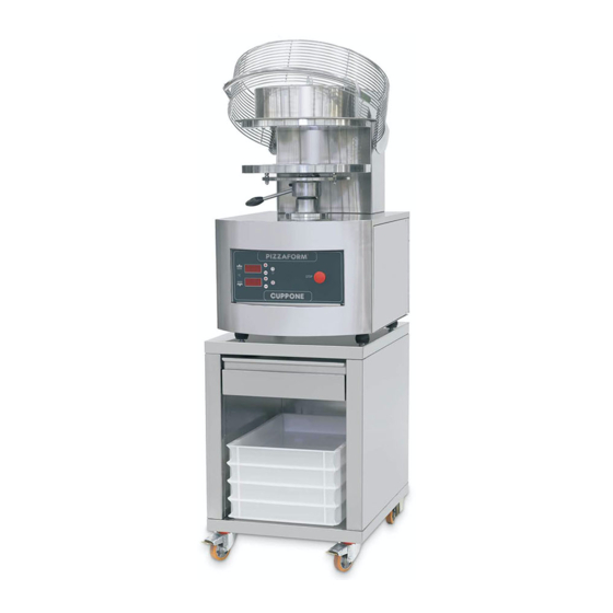
Cuppone Pizzaform
User and Installation Manual
Note: Pizza Equipment Professionals has provided this
manual as an English only copy of the Cuppone F. LLI SRL
Manual provided by the manufacturer. Words and
Descriptions may have been altered. If you have questions
please reference the Manufacturer's Manual you have
received with your purchase.
www.PizzaEquipmentPros.com 800.655.1831 17981 S. Ideal Parkway. Manteca, CA. 95336. U.S.A. info@PizzaEquipmentPros.com
1
Advertisement
Table of Contents

Subscribe to Our Youtube Channel
Related Manuals for Cuppone Pizzaform


Summary of Contents for Cuppone Pizzaform
- Page 1 Cuppone Pizzaform User and Installation Manual Note: Pizza Equipment Professionals has provided this manual as an English only copy of the Cuppone F. LLI SRL Manual provided by the manufacturer. Words and Descriptions may have been altered. If you have questions please reference the Manufacturer’s Manual you have...
- Page 2 INDEX Introduction Initial Instructions Explanation of Symbols Risk Analysis Technical Data (Pizzaform 30, 35) Technical Data (Pizzaform 40, 45, 50) General Specifications Installation Requirements Safety Distances Instructions for the Installer Uploading & Transport Preparations and Checks Positioning Electrical Connections Power Supply, Activation, Operation Verification...
-
Page 3: Initial Instructions
INTRODUCTION The present manual refers to various electronic control PIZZAFORM pizza hot forming machine models. The present manual was originally written in Italian. All other languages are translations. Congratulations on selecting a product that was designed and constructed with advanced technology. - Page 4 EXPLANATION OF SYMBOLS Warning Gear Risk of Crushing Fingers Risk of Blistering Equipotential Risk of Electric Wheels Surface Shock Warning: In case of Warning: Before using arrest of the plate, the equipment switch off and turn on carefully read the the machine.
-
Page 5: Risk Analysis
RISK ANALYSIS The machine was designed in compliance with the Machinery Directive 2006/42/EC and Legislative Decree no. 17 of the 27 January 2010. In compliance with these standards an assessment of the possible damage resulting from risks to health and the safety of operators of the machines in question, should a hazed come to light, was carried out. - Page 6 Ensure that you keep a distance of at least 500 mm (20 inches) between the equipment and other equipment of inflammable materials. We advise that you leave an unrestricted space of at least 500 mm to the right side to allow for easy access to the electrical system.
- Page 7 Ensure that you keep a distance of at least 500 mm (20 inches) between the equipment and other equipment of inflammable materials. We advise that you leave an unrestricted space of at least 500 mm to the right side to allow for easy access to the electrical system.
-
Page 8: General Specifications
GENERAL SPECIFICATIONS Iron supporting frame with thickness of 20 mm. Stainless steel body Self-braking motor (direct-current brake) with built-in thermal protection. Thick chromed plates with flared perimeter. Electronic control of temperature and plate contact time. EC certified safety devices. Lever to adjust the distance between plates. Protection grille. -
Page 9: Installation Requirements
INSTALLATION REQUIREMENTS Before starting the installation, check the following conditions that are necessary for proper equipment operation and maintenance: 1) Handling: Make sure that the floor is able to support the weight of the equipment. Handle the packaged equipment using a forklift or a pallet truck. 2) Electrical connection: Provide a box for the connection to the mains power supply in the immediate surroundings. -
Page 10: Instructions For The Installer
INSTRUCTIONS FOR THE INSTALLER The gas, water, electrical systems and the rooms where the equipment will be installed must comply with the safety, accident prevention and fire prevention standards applicable in the country of use; otherwise the Manufacturer shall not be liable for any direct or indirect damage to people or property. ATTENTION! Always shut off the main electric switch when installing, servicing or repairing the equipment. -
Page 11: Unloading And Transport
UNLOADING AND TRANSPORT PREPARATIONS AND CHECKS Unwrap the equipment and carefully remove the protective film. In the instance where glue residue remains on surfaces, remove then using soapy water; do not use corrosive products. ATTENTION! Check that all equipment parts are in good condition and that there are no defects or breakages;... - Page 12 POSITIONING The machine must be positioned on the appropriate support supplied by the company, which must be manufactured to satisfy the characteristics. In the case where it is placed above a different base, ensure that it is level and is able to support the weight (see the technical specifications table on pg.14).
-
Page 13: Electrical Connections
ELECTRICAL CONNECTIONS Only qualified personnel must carry out electrical connection. The technical data plate, located on the back of the equipment, contains all the necessary information for correct connection. The equipment must be connected to a power supply with a H05 RN-F type cable (supplied by the installer). To carry out this operation, remove the right side equipment panel, connect the cable to the terminal board and secure it with the relative cable gland located on the back of the equipment itself. -
Page 14: Operation Verification
POWER SUPPLY ACTIVATION OPERATION VERIFICATION Start up the equipment using the instructions provided below. Check the correct operation of all electrical components, whilst explaining how to best use the equipment and how to carry out routine maintenance and cleaning operations to the user. - Page 15 PRE-TEST Prior to delivery to the customer, the equipment is tested at the manufacturer’s workshops both with regard to functionality as well as to safety. When the unit is turned on for the first time is recommended that the temperature is set at 150°C and left on for at least 1 hour.
-
Page 17: Instructions For The User
INSTRUCTIONS FOR THE USER This equipment was designed exclusively for flattening dough balls to make pizza or similar food products as per the methods indicated in this booklet. Any use other than what is indicated is considered improper, potentially dangerous for people and animals and could cause irreparable damage to the equipment. - Page 18 TURNING ON Unblock the machine by turning the STOP key (12) clockwise. Switch the machine on by pressing the ON/OFF key (11). After a few sec the display (1) will present the top plate temperature and the display (3) the bottom plate temperature.
-
Page 19: Shutting Off
Wait until the plates have reached the set temperature; attempt to flatten a few balls by varying the plate distance using the lever (13) up until the desired depth has been achieved. Flattening is achieved by positioning the dough ball at the center of the bottom plate and keeping the protection grille (14) lowered. -
Page 20: Countdown Function
COUNTDOWN FUNCTION The board is equipped with a countdown function which automatically turns on the equipment. To activate this function, press Timer key (10) with the equipment turned off. The time remaining before the oven is due to turn itself on will appear on display (1);... -
Page 21: Troubleshooting
TROUBLE SHOOTING In case of a fault and or malfunctions, the following error messages will appear on the board display: “Err” on display (1): thermocouple upper heating element fault. “Err” on display (3): thermocouple lower heating element fault. “Err” on display (1) and “rot” on display (3) : motor error - cycle not completed in the time set with the “tUP”... - Page 22 Problem Cause Solution The dough sticks to the plates The plate temperature is too Low Check the set temperature on the thermostat and where necessary, raise it to 150 ° - 160° C The shape of the Dough Disc is The ball has not been placed at Place the ball at the centre of the bottom plate.
-
Page 23: Maintenance Instructions
MAINTENANCE INSTRUCTIONS The data plate, located on the back of the equipment, provides important technical information: this information is essential when making a request for maintenance or a repair for the equipment: therefore is it recommended not to remove, damage or modify it. ATTENTION: Prior to any routine or extraordinary maintenance operation, disconnect the equipment from the power supply;... - Page 24 POSITIONING OF MAIN CONTROLS All electrical components can be found inside the control box to the left of the equipment. You are able to access these components by removing the right side. Disconnect the electrical power supply before carrying out any of the following operations.
-
Page 25: Wiring Diagram
WIRING DIAGRAM Cable must be purchased at the expense of the client. Available to purchase from Pizza Equipment Professionals Protection at the Expense of the Client. -
Page 26: Warranty Conditions
The liability of “Cuppone F.lli s.r.l.” is limited to the supply of the device, which must be installed in a workmanlike manner by qualified... - Page 27 This is the only valid warranty and no one else is authorized to provide others in the name of or on behalf of “Cuppone F.lli s.r.l.”. WARRANTY SERVICES If during the warranty period defects appear or breakage is verified, the user must contact his reseller within 2 months of the date in which the defect was discovered with a tax document.
Need help?
Do you have a question about the Pizzaform and is the answer not in the manual?
Questions and answers