Table of Contents

Related Manuals for Beck IPC@CHIP - SC12

Summary of Contents for Beck IPC@CHIP - SC12
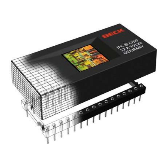
- Page 1 IPC@CHIP - SC12 Hardware Manual v1.1 [05.11.2002] Preliminary Hardware Manual High Performance, 80186- and 80188-Compatible, 16-Bit Embedded Microcontroller Single Chip PC with Ethernet 10Base-T, Flash, RAM, Watchdog ©BECK IPC GmbH page 1 of 28...
-
Page 2: Table Of Contents
IPC@CHIP - SC12 Hardware Manual v1.1 [05.11.2002] Table of Contents Page BASIC SPECIFICATIONS ......................3 PHYSICAL DIMENSIONS......................5 PIN CONFIGURATION ......................6 PIN FUNCTIONS ........................7 Address / Data bus.......................7 Programmable I/O Pins ....................8 Programmable Chip Selects ..................9 Interrupts ........................9 Timer ..........................10 10Base-T Interface.....................10 Asynchronous Serial Ports..................10... -
Page 3: Basic Specifications
Available in the following packages: 32-pin, plastic pack (DIL32) The @CHIP SC12 microcontrollers are part of the Beck IPC@CHIP® family of System on Chip microcontrollers and microprocessors based on the x86 architecture. The IPC@CHIP family microcontroller is the ideal solution for new designs requiring Ethernet TCP/IP communication over twisted pair and/or through the serial port. - Page 4 IPC@CHIP - SC12 Hardware Manual v1.1 [05.11.2002] The IPC@CHIP family microcontrollers also integrates the functions of the CPU, multiplexed address bus, three timers, watchdog timer, chip selects, interrupt controller, two DMA controllers, two asynchronous serial ports, and programmable I/O (PIO) pins on one chip.
-
Page 5: Physical Dimensions
IPC@CHIP - SC12 Hardware Manual v1.1 [05.11.2002] 2. PHYSICAL DIMENSIONS 44,0 43,0 2,54 15,24 IPC@CHIP 12A9912b GERMANY ©BECK IPC GmbH page 5 of 28... -
Page 6: Pin Configuration
IPC@CHIP - SC12 Hardware Manual v1.1 [05.11.2002] 3. PIN CONFIGURATION PIO7 / RXD0 PIO8 / TXD0 (I2C_SCL)* / DRQ1 / INT6 / PIO0 PIO9 / CTS0 (I2C_SDA)* / DRQ0 / INT5 / PIO1 PIO10 / RTS0 A2 / PCS6# / PIO2... -
Page 7: Pin Functions
IPC@CHIP - SC12 Hardware Manual v1.1 [05.11.2002] 4. PIN FUNCTIONS Pin Terminology The following terms are used to describe the pins: Input (I) - An input-only pin. Input (IS) - An input-only pin with Schmitt Trigger. Output (O) - An output-only pin. -
Page 8: Programmable I/O Pins
IPC@CHIP - SC12 Hardware Manual v1.1 [05.11.2002] Programmable I/O Pins Pin Name Type Function PIO[0..13] Programmable I/O Pins (input/output, open-drain) The IPC@CHIP family microcontroller provides 14 individually programmable I/O pins. Each PIO can be programmed with the following attributes: PIO function (enabled/disabled), direction (input/output), and weak pullup or pulldown. -
Page 9: Programmable Chip Selects
IPC@CHIP - SC12 Hardware Manual v1.1 [05.11.2002] Programmable Chip Selects Pin Name Type Function PCS[0..3] Peripheral Chip Selects (output) These pins indicate to the system that an I/O memory access is in progress to the corresponding region of the peripheral memory. -
Page 10: Timer
IPC@CHIP - SC12 Hardware Manual v1.1 [05.11.2002] Timer Timer can be clocked internally or externally. Maximum frequency is 5MHz. If timer will be clocked internally timer out pin (TMROUT) may be used. External clock at Input and output at the same time with same timer is not possible. -
Page 11: Dma
IPC@CHIP - SC12 Hardware Manual v1.1 [05.11.2002] Pin Name Type Function TxD[0..1] Transmit Data (output) These pins supply asynchronous serial transmit data to the system from serial port 0 and 1. RxD[0..1] Receive Data (input) These pins supply asynchronous serial receive data from the system to asynchronous serial ports 0 and 1. -
Page 12: I 2 C-Bus
IPC@CHIP - SC12 Hardware Manual v1.1 [05.11.2002] C-Bus The IPC@CHIP family microcontroller handles up to 127 external slaves. It is always master. Slave mode is not implemented. I²C is implemented by software emulation. Maximum Frequency is about 30 kHz without longer breaks by interrupt. - Page 13 IPC@CHIP - SC12 Hardware Manual v1.1 [05.11.2002] Pin Name Type Function The NMI is for detecting low supply power and the following data backup only. A reset has to follow after the NMI. At turn-on the IPC@Chip I/O pins are configured as follows:...
- Page 14 IPC@CHIP - SC12 Hardware Manual v1.1 [05.11.2002] Power up & power down sequence 4,65 V 4,7 V =Time to save the retentive data Power OK e. g. 1 kByte = 120 ms 2 kByte = 200 ms = max. 200 ms Power OK Note: Retentive data must be one block.
-
Page 15: Mutual Exclusive Functions
IPC@CHIP - SC12 Hardware Manual v1.1 [05.11.2002] 5. MUTUAL EXCLUSIVE FUNCTIONS The IPC@CHIP family microcontroller provides a lot of different functions by several multi-function pins. Choosing one function will result in disabling other functions. The following table shows, which functions are mutual exclusive. - Page 16 IPC@CHIP - SC12 Hardware Manual v1.1 [05.11.2002] Pin Name Function Exclusion PI11 Programmable I/O Serial Port 1 PI12 Programmable I/O Serial Port 1, INT3 PI13 Programmable I/O INT0, cascaded Interrupt Controller *, TMROUT0 RxD0, TxD0 Serial Port 0 w/o hw flow PIO[7..8]...
-
Page 17: Ethernet 10Base-T
IPC@CHIP - SC12 Hardware Manual v1.1 [05.11.2002] 6. ETHERNET 10BASE-T 10Base-T Media Filter Placement and Termination Placement of the termination components TPTX+ and TPTX- should be located as physically close to the media filter as possible. The media filter should also placed as physically close to the RJ-45 connector as possible to minimize stray EMI transfer to the media. -
Page 18: System Overview
IPC@CHIP - SC12 Hardware Manual v1.1 [05.11.2002] 7. SYSTEM OVERVIEW IPC@CHIP family microcontroller has a system configuration based on the ISA architecture with some changes: No ISA-Bus, no Video-Interface, no Keyboard Interface, programming of Serial Ports, DMA, PIC and Timer is different from standard IBM PC. -
Page 19: System Interrupts
IPC@CHIP - SC12 Hardware Manual v1.1 [05.11.2002] System interrupts Source Sensitivity Number of Interrupt 0 = INT0 (external) Edge / Level 1 = Network controller (internal) 2 = INT2 (external) Edge / Level 3 = INT3 (external) Edge / Level... -
Page 20: Characteristics
IPC@CHIP - SC12 Hardware Manual v1.1 [05.11.2002] 8. CHARACTERISTICS ABSOLUTE MAXIMUM RATINGS Storage temperature : -55°C to +125°C see IEC 68-2-1/2 Supply voltage (Vcc) : -0.3V to +6.0V Supply current (Vcc = 5,25V) : 300 mA Voltage on any pin with respect to ground : -0.3V to Vcc + 0.3V... -
Page 21: Ac-Characteristics
IPC@CHIP - SC12 Hardware Manual v1.1 [05.11.2002] AC-CHARACTERISTICS 8.4.1 Read Cycle Symbol Description Unit General Timing Requirements Read Valid to Data Valid – PCS0#..PCS3# Active 820 RLDV Read Valid to Data Valid – PCS5#, PCS6# Active 220 RLDV General Timing Responses... -
Page 22: Write Cycle
IPC@CHIP - SC12 Hardware Manual v1.1 [05.11.2002] 8.4.2 Write Cycle Symbol Description Unit General Timing Responses ALE Width LHLL AD Address Valid to ALE Low AVLL PCSx# Hold from Read Inactive CXCSX ALE High to Address Valid LHAV PCSx# Active to ALE Inactive... -
Page 23: Environmental Test
IPC@CHIP - SC12 Hardware Manual v1.1 [05.11.2002] 9. ENVIRONMENTAL TEST Following stability tests in conjunction with FEC standard are carried out (device under test inoperative): Dry heat and cold resistance DIN EN60068- 2-2 Bb / 2-1 Ab +70°C, 96h / –25°C, 96h... -
Page 24: Application Examples
IPC@CHIP - SC12 Hardware Manual v1.1 [05.11.2002] APPLICATION EXAMPLES The following pages contain schematics showing the IPC@CHIP family microcontroller gives you suggestions, how to handle the multi-function pin 17 RESET# / NMI / LINK-LED and how to expand the SC12. -
Page 25: Link-Led / Reset
IPC@CHIP - SC12 Hardware Manual v1.1 [05.11.2002] 10.2 Link-LED / Reset SC12 3,5..4V <0,8V RESET = 1..5mA (static) 10.3 256x 8bit I/O-Extension using 74HCT573/245 74HC573 TPTX+ TPTX- TPRX+ TPRX- RX D0 PIO7 TXD0 PIO8 CTS0 PIO9 ENRX 0 RTS0 PIO10 RTR0... -
Page 26: Connect 10Base-T Ethernet To The Sc12
IPC@CHIP - SC12 Hardware Manual v1.1 [05.11.2002] 10.4 Connect 10Base-T Ethernet to the SC12 IPC@CHIP SC12 TPTX+ TPTX- TPRX+ TPRX- RJ45 SF1012 VALORSMD 10nF 10nF IPC@CHIP SC12 TPTX+ TPTX- TPRX+ TPRX- VALOR RJ45 FL1066 10nF 10nF IPC@CHIP SC12 FS22-101Y 4... -
Page 27: Errata List
IPC@CHIP - SC12 Hardware Manual v1.1 [05.11.2002] ERRATA LIST (Changes since last document Hardware Manual v1.0) Page 6, Chapter 3: PIN CONFIGURATION: Wrong pin names at pin18 and pin 19 Page 10, Chapter 4.6: LINK LED The traffic hi-pulse width and the sink output voltage were not right. -
Page 28: Contact
The information in this document is subject to change without Right to make changes — BECK IPC GmbH reserves the right notice. Devices sold by BECK IPC GmbH. Are covered by to make changes, without notice, in the products, including...
Need help?
Do you have a question about the IPC@CHIP - SC12 and is the answer not in the manual?
Questions and answers