Table of Contents
Advertisement
Advertisement
Table of Contents

Subscribe to Our Youtube Channel
Related Manuals for Milltronics airanger XPL plus


Summary of Contents for Milltronics airanger XPL plus
- Page 1 Instruction Manual March 2005 airanger XPL PLUS...
- Page 2 The user is responsible for all changes and repairs made to the device by the user or the user’s agent. • All new components are to be provided by Siemens Milltronics Process Instruments Inc. • Restrict repair to faulty components only.
-
Page 3: Table Of Contents
Table of Contents ..............................1 Introduction About This Manual ..........................1 About the AiRanger XPL Plus ......................2 Important AiRanger XPL Plus Features .....................4 ..............................7 Installation AiRanger XPL Plus ..........................7 Optional Cards ............................9 Interconnection ............................10 ...............................15 Programming Display ..............................15 Keypad ..............................16 Program Mode Entry ..........................17 Parameter Value Alteration ........................17... - Page 4 Measurement Parameters (P920 to P923) ..................74 Master Reset (P999) ..........................77 ..........................79 Technical Reference Transmit Pulse ............................79 Echo Processing ............................79 Distance Calculation ..........................80 Sound Velocity ............................80 Scanning ..............................81 Volume Calculation ..........................81 Measurement Response ........................82 Application Examples ...........................83 BIC-II Support ............................93 Maintenance ............................96 ..........................97 Troubleshooting Guide Measurement Difficulties ........................98...
-
Page 5: Introduction
After reading this introduction and completing the physical installation, first time system installers may wish to use the AiRanger XPL Plus Quick Start Guide for step-by-step start up instructions. introduces installers and operators to the XPL Plus, with brief Introduction descriptions of key features. -
Page 6: About The Airanger Xpl Plus
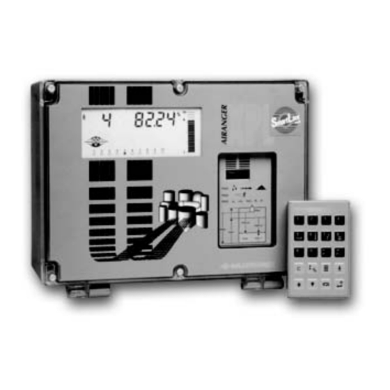
About the AiRanger XPL Plus The AiRanger XPL Plus is to be used only in the manner outlined in this instruction manual. The XPL Plus is a microprocessor based level monitor designed specifically for bulk solids and liquid level measurement applications. An XPL Plus level monitor, utilizing a single Siemens Milltronics ultrasonic transducer, accurately monitors vessel material level without material contact. - Page 7 Readings. The Reading chosen (and operating data) for each vessel is displayed on the Liquid Crystal Display (LCD). Up to three Siemens Milltronics Peripherals may be connected to the XPL Plus. The AO- 10, SAM-20 and/or BIC-II, respectively provide analog output , relays, and RS-232 or RS- 422 communication interface, as programmed by the XPL Plus.
-
Page 8: Important Airanger Xpl Plus Features
Sonic Intelligence® ensures all measurements are accurate and reliable. Immune to power interruptions, all programming is stored indefinitely. Dynamic operating data is retained for one hour and updated immediately on power resumption. Page 4 AiRanger XPL Plus – INSTRUCTION MANUAL 7ML19981AN02... - Page 9 Fixed or independent on/off setpoints. (SAM-20 required) Based on level, space, distance, or volume. mA Outputs 4 range selections, 0-20, 4-20, 20-0, or 20-4 mA. (AO-10 required) Adjustable range and over-range limits. 7ML19981AN02 AiRanger XPL Plus – INSTRUCTION MANUAL Page 5...
- Page 10 Page 6 AiRanger XPL Plus – INSTRUCTION MANUAL 7ML19981AN02...
-
Page 11: Installation
AO-10 (if used) • Synchronization (see Interconnection-Level System Synchronization) • Power Transducer cables must be run in a grounded metal conduit, separate Note: from other wiring, (except TS-3 temperature sensor wiring, if applicable). 7ML19981AN02 AiRanger XPL Plus – INSTRUCTION MANUAL Page 7... - Page 12 ST-100, LR-21, XLT-30, XLS-30 1.32 m (4.33 ft) LR-13, XLT-60, XLS-60 This is the recommended minimum distance. However, it can be reduced under certain circum- stances. Please check the appropriate transducer manual for details. Page 8 AiRanger XPL Plus – INSTRUCTION MANUAL 7ML19981AN02...
-
Page 13: Optional Cards
Optional Cards Communications Module The XPL Plus is software / hardware ready to accept an optional Siemens Milltronics SmartLinx communications module that provides an interface to one of several popular industrial communications systems. Your XPL Plus may be shipped to you without a SmartLinx module, for installation at later date. -
Page 14: Interconnection
XPL PLUS __________ board B optional terminal block EPROM TIB-9 voltage selection All field wiring must have insulation suitable for at least 250 V. Hazardous voltage is present on transducer terminals during operation. Page 10 AiRanger XPL Plus – INSTRUCTION MANUAL 7ML19981AN02... - Page 15 Milltronics SAM-20, relay output device Milltronics BIC-2, buffered interface converter industry bus industry control system Maximum system capability. Not all components or their maximum quantity may be required. 7ML19981AN02 AiRanger XPL Plus – INSTRUCTION MANUAL Page 11...
- Page 16 Use Belden 8760 (or equivalent ) 18 AWG, 2 wire shielded / twisted, 365 m (1200 ft) per TS-3 max. Use TS-3 temperature sensors only. Don’t jumper the terminals if TS-3’s are not used. Peripherals The XPL Plus is compatible with the following Siemens Milltronics peripherals (3 max.): • SAM-20: 20 relay satellite alarm module (2 max.) •...
- Page 17 2. Ensure the level monitors share a common power (mains) supply, and ground (earth). 3. Interconnect the SYNC terminals of the level monitors to be synchronized. To synchronize the XPL Plus with other Siemens Milltronics ultrasonic level monitors (not listed) contact Siemens Milltronics or your local distributor. 7ML19981AN02 AiRanger XPL Plus –...
- Page 18 A circuit breaker or switch in the building installation, marked as the disconnect switch, shall be in close proximity to the equipment and within easy reach of the operator. Page 14 AiRanger XPL Plus – INSTRUCTION MANUAL 7ML19981AN02...
-
Page 19: Programming
Parameter Value may be scroll accessed. PROGRAM mode indicates the PROGRAM mode is accessed. Point in Service indicates the Point Numbers which will be scanned in the RUN mode. 7ML19981AN02 AiRanger XPL Plus – INSTRUCTION MANUAL Page 15... -
Page 20: Keypad
Parameter Value in memory (complete a parameter reset). switch the Parameter Value to % or Units (access Auxiliary Parameter Function). increase the accessed display value. decrease the accessed display value. take an ultrasonic measurement. enter the RUN mode. Page 16 AiRanger XPL Plus – INSTRUCTION MANUAL 7ML19981AN02... -
Page 21: Program Mode Entry
With the desired Parameter Number and Point Number displayed, key in the desired Parameter Value and press If Parameter Value alteration is not permitted, access the Lock parameter (P000) and enter the security code (See Programming Security). 7ML19981AN02 AiRanger XPL Plus – INSTRUCTION MANUAL Page 17... -
Page 22: Programming Security
To unLock, direct access this parameter and enter the value "1954". This parameter cannot be reset by pressing values: 1954 = off (Parameter Value alteration permitted) other = activated (programming secured) Page 18 AiRanger XPL Plus – INSTRUCTION MANUAL 7ML19981AN02... -
Page 23: Quick Start Parameters
Enter the type of material to be monitored. If the material presents a flat surface perpendicular to the transducer beam, select liquid. values: 1 = liquid or flat surface (preset) 2 = solid 7ML1998AN02. 1 AiRanger XPL Plus – INSTRUCTION MANUAL Page 19... - Page 24 Enter the units of measure desired for programming Empty (P006) and Span (P007). values: 1 = meters (m) (preset) 2 = centimeters (cm) 3 = millimeters (mm) 4 = feet (ft) 5 = inches (in) Page 20 AiRanger XPL Plus – INSTRUCTION MANUAL 7ML19981AN02...
- Page 25 Installation. Always prevent the monitored surface from entering the blanking zone. values: 0.000 to 9999 With the Quick Start Parameters altered as required, proceed to Operation to identify / verify basic system performance. 7ML1998AN02. 1 AiRanger XPL Plus – INSTRUCTION MANUAL Page 21...
- Page 26 Page 22 AiRanger XPL Plus – INSTRUCTION MANUAL 7ML19981AN02...
-
Page 27: Operation
Point scanned (independent from the Point Number display). Normal Operation indicates operating conditions are good and the Reading is reliable. Failsafe Operation indicates operating conditions are poor and the Reading may be incorrect. 7ML19981AN02 AiRanger XPL Plus – INSTRUCTION MANUAL Page 23... -
Page 28: Keypad
/ starts the Point Number auto display scroll. selects the next Point Number (and stops the auto display scroll). selects the previous Point Number (and stops the auto display scroll). places a Point Number on priority (See P720). Page 24 AiRanger XPL Plus – INSTRUCTION MANUAL 7ML19981AN02... -
Page 29: System Performance Evaluation
All associated data is supplied to the Peripheral Communications terminals (42 Note: Technical Reference and 43). If a BIC-II is connected, refer to BIC-II Support for message format and protocol information. 7ML19981AN02 AiRanger XPL Plus – INSTRUCTION MANUAL Page 25... -
Page 30: Performance Test Results
Connect (or enable) process control / alarm equipment to the XPL Plus only after satisfactory performance is verified for all possible operating conditions. For normal operation, return to the RUN mode. The XPL Plus will perform reliably, with little or no maintenance. Page 26 AiRanger XPL Plus – INSTRUCTION MANUAL 7ML19981AN02... -
Page 31: Application Parameters
(P052) Universal Linear (P054 / P055) cone / pyramid bottom (P052) flat ends parabola bottom (P052) Universal Curved (P054 / P055) 10 = parabola ends (P052 / P052) 7ML19981AN02 AiRanger XPL Plus – INSTRUCTION MANUAL Page 27... - Page 32 2. Scroll ( ) or direct access the desired Breakpoint. 3. Key in the desired level or volume value. 4. Press Technical Reference Refer to Volume Calculation for breakpoint value selection. Page 28 AiRanger XPL Plus – INSTRUCTION MANUAL 7ML19981AN02...
-
Page 33: Reading Parameters (P060 To P062)
If the Reading is currently displayed in feet, to display in yards, enter 3. Avoid entering a value that, when multiplied by the maximum current reading, could exceed 5 digits before the Decimal Position values: -999 to 9999 7ML19981AN02 AiRanger XPL Plus – INSTRUCTION MANUAL Page 29... -
Page 34: Failsafe Parameters (P070 To P072)
Reading, Bar Graph, SAM-20 relays (if used) and AO-10 mA outputs (if used), at their last known values. To operate process control equipment under these conditions, alter the following parameters as required. If alternate Failsafe Operation is not required, proceed to RELAY PARAMETERS. Page 30 AiRanger XPL Plus – INSTRUCTION MANUAL 7ML19981AN02... - Page 35 (when process control equipment is used) avoid entering a value so short as to cause nuisance activation. This feature is automatically altered when Measurement Response (P003) is altered. values: 0.000 to 9999 7ML19981AN02 AiRanger XPL Plus – INSTRUCTION MANUAL Page 31...
- Page 36 Otherwise, when "fastback" is selected, the Failsafe Level Advance is restricted, however the advance to the new material level (when a valid measurement is made) is immediate. values: 1 = restricted 2 = immediate 3 = fastback Page 32 AiRanger XPL Plus – INSTRUCTION MANUAL 7ML19981AN02...
-
Page 37: Relay Parameters (P100 To P104, P110 To P113, P129)
Relay Function (P111) and Relay A / B Setpoints (P112/P113) are automatically reset when a Relay Set Up value is altered. values: 1 = Set Up 1 2 = Set Up 2 3 = Set Up 3 7ML19981AN02 AiRanger XPL Plus – INSTRUCTION MANUAL Page 33... - Page 38 Use Relay A / B Setpoints (P112 / P113) instead. If Custom Relay operation is not required, proceed to Relay Failsafe (P129). "OFF" is displayed if the Relay Set Up (P100) selected does not use the Alarm parameter accessed. Page 34 AiRanger XPL Plus – INSTRUCTION MANUAL 7ML19981AN02...
- Page 39 Failsafe Timer (P700) expiry Cable Fault no designation relay de-energizes under transducer short or opened condition. The Relay Designation is included in the BIC-II (if used) data message (not displayed). 7ML19981AN02 AiRanger XPL Plus – INSTRUCTION MANUAL Page 35...
- Page 40 Celsius (°C). Rate alarms are entered in Units/minute or percent of Span per minute. A positive value is entered for a filling rate alarm, negative for emptying. Page 36 AiRanger XPL Plus – INSTRUCTION MANUAL 7ML19981AN02...
- Page 41 Enter the critical point for the desired action to occur (based on the Relay Function selected). values: -999 to 9999 P113 RELAY B SETPOINT Enter the critical point for the desired action to occur (based on the Relay Function selected). values: -999 to 9999 7ML19981AN02 AiRanger XPL Plus – INSTRUCTION MANUAL Page 37...
- Page 42 To select an independent Relay Failsafe option value: to display to the Auxiliary Function symbol, 1. Press to scroll access the failsafe options. 2. Press with the desired option displayed. 3. Press values: "OFF" "HOLd" "dE" "En" Page 38 AiRanger XPL Plus – INSTRUCTION MANUAL 7ML19981AN02...
-
Page 43: Ma Output Parameters (P200 To P203, P210 To P215, P219)
Operation (P001). If a Tank Shape (P050) is programmed, the mA Function automatically corresponds to volume (unless the mA Allocation has been altered). values: 1 = level 2 = space 3 = distance 4 = volume 7ML19981AN02 AiRanger XPL Plus – INSTRUCTION MANUAL Page 39... - Page 44 Allocation (P202) range. If more than one mA output is allocated to the same Point Number, the value of the lowest mA Output Number is displayed. values: 0.000 to 22.00 Page 40 AiRanger XPL Plus – INSTRUCTION MANUAL 7ML19981AN02...
- Page 45 MAX LIMIT Use this feature to prevent the mA output from exceeding the maximum acceptable mA input value (preset to 20.20 mA) of the device connected. values: 0.000 to 22.00 7ML19981AN02 AiRanger XPL Plus – INSTRUCTION MANUAL Page 41...
- Page 46 "HI" to produce the "Span" mA output immediately on Failsafe Timer (P070) expiry. Alternatively, to produce an immediate mA output at a specific value, enter the value required. values: 0.000 to 22.00 Page 42 AiRanger XPL Plus – INSTRUCTION MANUAL 7ML19981AN02...
-
Page 47: Enhancement Parameters
Page Data Logging to view previous maximum Temperature records Profile Records intended for use by Siemens Milltronics Service personnel Installation Records to identify length of service and power failure occurrence Range Calibration to compensate for measurement offset and/or sound velocity... -
Page 48: Profile Records (P330 To P337)
Number field. values: -50 to 150 Profile Records (P330 to P337) The following parameters are for authorized Siemens Milltronics service personnel or Instrumentation Technicians familiar with Siemens Milltronics echo processing techniques. Use these features to record and save a total of up to 10 Echo profiles, initiated manually (P330), or automatically (P331 et al). - Page 49 Parameter value e.g.record deleted, address 3 returns to ‘ - - - - ’ clear * Access the Scope Displays (P810) parameter to select the Transducer. 7ML19981AN02 AiRanger XPL Plus – INSTRUCTION MANUAL Page 45...
- Page 50 P334 (G) AUTO RECORD A SETPOINT Enter the critical level which, in conjunction with Auto Record B Setpoint, defines the boundaries for Auto Profile Records to be saved. values: -999 to 9999 Page 46 AiRanger XPL Plus – INSTRUCTION MANUAL 7ML19981AN02...
-
Page 51: Installation Records (P340 To P342)
Installation Records (P340 to P342) Use these features to view data relating to this specific XPL Plus installation. P340 (V) DATE OF MANUFACTURE View the date of manufacture of this XPL Plus. values: YY:MM:DD format 7ML19981AN02 AiRanger XPL Plus – INSTRUCTION MANUAL Page 47... -
Page 52: Range Calibration Parameters (P650 To P654)
2. Repeat step 1 at least 5 times to overcome Echo Lock (P721) and verify repeatability. 3. Measure the actual distance* (e.g. with a tape measure). 4. Enter the actual value. (The Offset Correction amount is stored in P652). values: -999 to 9999 Page 48 AiRanger XPL Plus – INSTRUCTION MANUAL 7ML19981AN02... - Page 53 Alternatively, if the amount of Offset Correction required is known (and performing an Offset Calibration is not desired), enter the amount to be added to the Reading before display. values: -999 to 9999 7ML19981AN02 AiRanger XPL Plus – INSTRUCTION MANUAL Page 49...
- Page 54 The units used are m/s if P005 = 1, 2, or 3 (or ft/s if P005 = 4 or 5). values: 50.01 to 2001 m/s (164.1 to 6563 ft/s) Page 50 AiRanger XPL Plus – INSTRUCTION MANUAL 7ML19981AN02...
-
Page 55: Temperature Compensation Parameters (P660 To P664)
Enter the temperature (in °C) of the vessel atmosphere within the transducer beam. If the temperature varies with distance from the transducer, enter the average temperature. This value is preset to 20.00 °C. values: -50 to 150 7ML19981AN02 AiRanger XPL Plus – INSTRUCTION MANUAL Page 51... - Page 56 If Temp Source (P660) is set to any value other than Fixed Temp, the value displayed is the temperature measured. If Temp Source is set to Fixed Temp, the P661 value is displayed. values: -50 to 150 Page 52 AiRanger XPL Plus – INSTRUCTION MANUAL 7ML19981AN02...
-
Page 57: Rate Parameters (P700 To P707)
Enter the empty rate to activate the LCD Material Emptying indicator and Smart Scan (P720). This value (in Units (P005) or % of Span (P007) per minute) is automatically set to 10% of the Max Empty Rate (P701). values: -999 to 9999 7ML19981AN02 AiRanger XPL Plus – INSTRUCTION MANUAL Page 53... - Page 58 View the rate of material level change (in Units (P005) or % of Span (P007) per minute). (A negative rate indicates the vessel is emptying). This is the value displayed when is pressed in the RUN mode. values: 0.000 to 9999 Page 54 AiRanger XPL Plus – INSTRUCTION MANUAL 7ML19981AN02...
-
Page 59: Measurement Verification Parameters (P710 To P713)
Max Fill / Empty Rate (P700 / P701); however, measurement reliability is affected. values: 0 = off 1 = maximum verification 2 = material agitator 3 = total lock 7ML19981AN02 AiRanger XPL Plus – INSTRUCTION MANUAL Page 55... - Page 60 For slower Measurement Response (P003) values the calculated Echo Lock Window is narrow. For faster values the window becomes increasingly wider, (When "TURBO" is selected the window is normally wide open). values: 0.000 to 9999 Page 56 AiRanger XPL Plus – INSTRUCTION MANUAL 7ML19981AN02...
-
Page 61: Scanning Parameters (P720, P725 To P729)
LEVEL SYSTEM SYNC Use this feature if another level measurement system is mounted near the XPL Plus. Installation Interconnection-Level System Synchronization. values: 0 = not required 1 = synchronize level monitors (preset) 7ML19981AN02 AiRanger XPL Plus – INSTRUCTION MANUAL Page 57... - Page 62 View the time elapsed (in seconds) since the point displayed was last scanned. This value may be viewed as an Auxilliary Reading in the Run mode (especially Operation useful when setting up Smart Scan, P720). See Keypad. values: 0.000 to 9999 Page 58 AiRanger XPL Plus – INSTRUCTION MANUAL 7ML19981AN02...
-
Page 63: Display Parameters (P730 To P734, P740)
Enter the delay (in seconds) before the display advances to the next Point Number. (Point Number display scrolling is independent from transducer scanning.) values: 0.5 to 10 (preset to 1.5 seconds) 7ML19981AN02 AiRanger XPL Plus – INSTRUCTION MANUAL Page 59... - Page 64 Refer to Technical Reference BIC-II Support if a BIC-II is used. values: 0 = off 1 = normal (preset) 2 = formatted messages Page 60 AiRanger XPL Plus – INSTRUCTION MANUAL 7ML19981AN02...
-
Page 65: Smartlinx Parameters
This register increments by 1 each time a bus error (P752) is reported. The register is factory set at 0 and can be preset to any value. The register is reset to 0 by master reset (P999). 7ML19981AN02 AiRanger XPL Plus – INSTRUCTION MANUAL Page 61... -
Page 66: Echo Processing Parameters (P800 To P807)
If Empty is substantially higher than the actual vessel bottom, increase Range Extension such that Empty plus Range Extension is greater than the transducer to vessel bottom distance. This value is automatically preset to 20% of Span (P007). values: 0.000 to 9999 Page 62 AiRanger XPL Plus – INSTRUCTION MANUAL 7ML19981AN02... - Page 67 Echo Confidence (P805) of a particular echo exceeds the Confidence Threshold, that echo is considered for evaluation by Sonic Intelligence®. values: x.y x = short (0 to 99), y = long (0 to 99) 7ML19981AN02 AiRanger XPL Plus – INSTRUCTION MANUAL Page 63...
- Page 68 The noise level is a combination of transient acoustic noise and electrical noise (induced into the transducer cable or receiving circuitry itself). values: x:y x = average (-99 to 99), y = peak (-99 to 99) Page 64 AiRanger XPL Plus – INSTRUCTION MANUAL 7ML19981AN02...
-
Page 69: Advanced Echo Processing (P810,P816-P825,P830-P835,P840-P845,P850-P852)
Advanced Echo Processing (P810,P816-P825,P830- P835,P840-P845,P850-P852) The following Echo Processing parameters are intended for use by authorized Siemens Milltronics Service personnel or Industrial Instrumentation Technicians familiar with Siemens Milltronics ultrasonic echo processing techniques. P810 SCOPE DISPLAYS Use this feature to monitor the results of Echo Processing parameter alterations. - Page 70 Profile Pointer. values: 0.000 to 9999 P819 (V) PROFILE POINTER AMPLITUDE Observe the amplitude (in dB above 1µV) of the Echo Profile at the Profile Pointer position. values: 0 to 99 Page 66 AiRanger XPL Plus – INSTRUCTION MANUAL 7ML19981AN02...
- Page 71 Enter the width of false echoes (in ms) to be removed from the long shot Echo Profile. When a value is keyed in, the nearest acceptable value is entered. values: 0 = off (preset), greater = wider 7ML19981AN02 AiRanger XPL Plus – INSTRUCTION MANUAL Page 67...
- Page 72 Adjust has been used to modify the TVT Curve (to avoid a false echo or pick up the true echo), this feature allows the TVT Shaper to be turned "on" and "off" while monitoring the effect. values: 0 = off 1 = on Page 68 AiRanger XPL Plus – INSTRUCTION MANUAL 7ML19981AN02...
- Page 73 To select another transducer Press to set the point number to transducer. Select desired transducer point. e.g. return to transducer 1 P831, TVT shaper, must be ‘ on ’ . 7ML19981AN02 AiRanger XPL Plus – INSTRUCTION MANUAL Page 69...
- Page 74 Enter the number of long shots to be fired (and results averaged) per transmit pulse. This value is automatically altered when Measurement Response (P003) is Technical Reference altered. (See Measurement Response). values: 0 to 200 Page 70 AiRanger XPL Plus – INSTRUCTION MANUAL 7ML19981AN02...
- Page 75 SHORT SHOT RANGE Enter the maximum distance in Units (P005) to be measured using short shot echoes. This feature is automatically altered when Transducer (P004) is altered. values: 0.000 to 9999 7ML19981AN02 AiRanger XPL Plus – INSTRUCTION MANUAL Page 71...
-
Page 76: Test Parameters (P900 To P913)
Test Parameters (P900 to P913) Test Parameters are intended for use by Siemens Milltronics Service personnel. P900 (V) SOFTWARE REV. # Access this parameter to determine the EPROM Rev. # without removing the enclosure lid. values: 00.00 to 99.99 P901 (V) MEMORY Press to activate the XPL Plus memory test. - Page 77 10.00 to 60.00 P906 COMMUNICATIONS to test the Siemens Milltronics proprietary communications circuit. Press Before activating this feature, connect terminal block contacts 42 to 45 and 43 to 46. On successful test completion, "PASS" is displayed. If "FAIL" is displayed, repeat the test.
-
Page 78: Measurement Parameters (P920 To P923)
BIC-II (if used). If measurements or simulation are desired but the XPL Plus operation has not been verified, disable all associated process control equipment before accessing the following parameters. Page 74 AiRanger XPL Plus – INSTRUCTION MANUAL 7ML19981AN02... - Page 79 The Reading corresponds to the volume calculation in percent of Max Volume (P051). to display in Max Volume units. Press P927 DISTANCE PERCENT same as P923, plus alternate reading in % press 7ML19981AN02 AiRanger XPL Plus – INSTRUCTION MANUAL Page 75...
- Page 80 Enter the point number to copy from. To copy a parameter set with the desired transducer point selected: e.g. point 4 Enter the point to copy from. Press e.g. copy from point 1 Press copying copy complete Page 76 AiRanger XPL Plus – INSTRUCTION MANUAL 7ML19981AN02...
-
Page 81: Master Reset (P999)
2. With the Point Number field accessed, key in the Point Number to be reset (1 - 10). 3. Press , "C.ALL" is displayed until the reset is complete. P999 is not accessible via SmartLinx Interface. 7ML19981AN02 AiRanger XPL Plus – INSTRUCTION MANUAL Page 77... - Page 82 Page 78 AiRanger XPL Plus – INSTRUCTION MANUAL 7ML19981AN02...
-
Page 83: Technical Reference
Fuzz Filter ( P710 ) and Rate Parameters ( P700 to P703 ). If the new echo is outside of the Echo Lock Echo Lock Window, the new echo is not accepted until ( measurement repeatability, P711 ) requirements are satisfied. 7ML19981AN02 AiRanger XPL Plus – INSTRUCTION MANUAL Page 79... -
Page 84: Distance Calculation
20°C (68°F). Unless altered, the sound velocity used for the distance calculation is 344.1 m/s (1129 ft/s). Variable air temperature is automatically compensated when a Siemens Milltronics ultrasonic / temperature transducer is used. If the transducer(s) are exposed to direct sunlight, TS-3 temperature sensor(s) should be used. -
Page 85: Scanning
From this graph, determine which Universal Volume calculation will provide the best results, and select the level vs volume breakpoints to be entered (32 max.). Generally, the more breakpoints entered, the greater the volume calculation accuracy. 7ML19981AN02 AiRanger XPL Plus – INSTRUCTION MANUAL Page 81... -
Page 86: Measurement Response
(as well as one breakpoint exactly at the angle) on the curve. Measurement Response The XPL Plus Measurement Response (P003) to material level change is designed to exceed the most demanding installation requirements. Page 82 AiRanger XPL Plus – INSTRUCTION MANUAL 7ML19981AN02... -
Page 87: Application Examples
EXAMPLE 1. Level (or Material Volume) Measurement for a single vessel. EXAMPLE 2. Space (or Remaining Vessel Capacity) Measurement for a single vessel. EXAMPLE 3. Multi-point Average EXAMPLE 4. Distance Measurement (less than 60 m). 7ML19981AN02 AiRanger XPL Plus – INSTRUCTION MANUAL Page 83... - Page 88 • a SAM-20 is connected as BANK 1 to the Peripheral Communications terminals. transducer 30.00 m (P006) 25.00 (P101) 29.01 m (P007) 27.00 m (P103) 10.00 m (P102) 5.00 m (P104) Page 84 AiRanger XPL Plus – INSTRUCTION MANUAL 7ML19981AN02...
- Page 89 When the reported level reaches 25.55 m (5% of Span less than the high high alarm trip point), the high high alarm goes off, restarting the infeed and filling the vessel to 27.00 m. 7ML19981AN02 AiRanger XPL Plus – INSTRUCTION MANUAL Page 85...
- Page 90 P050 Tank shape Enter "1" for vertical cylinder with flat bottom. P051 Max Volume Enter "1457" for 1457 m Now in the RUN mode the Reading represents material volume in m Page 86 AiRanger XPL Plus – INSTRUCTION MANUAL 7ML19981AN02...
- Page 91 Enter "4.5" for 4.50 ft (3 feet diameter plus 1.5 ft in standpipe). P007 Span Enter "3" for 3 ft (vessel diameter). P070 Failsafe Timer Enter ".1" for 6 seconds. P071 Failsafe Material Level Enter "Lo" for advance to Empty on "LOE". 7ML19981AN02 AiRanger XPL Plus – INSTRUCTION MANUAL Page 87...
- Page 92 Now in the RUN mode, the Reading Value and AO-10 mA output represents remaining vessel capacity in cubic feet. If the mA output is still to be scaled to "space" (distance from material to Full in feet) set the mA Function (P201) to "2". Page 88 AiRanger XPL Plus – INSTRUCTION MANUAL 7ML19981AN02...
- Page 93 P006 Empty Enter "65" for transducer face to Empty equals 65 ft. P007 Span Enter "60" for max material level equals 60 ft. P070 Failsafe Timer Enter "2" for 2 minutes 7ML19981AN02 AiRanger XPL Plus – INSTRUCTION MANUAL Page 89...
- Page 94 1 hour minimum. If power is interrupted beyond 1 hour, on power resumption, the mA output immediately assumes the "new value". If a Tripper Car is used to fill each section of the bunker, see Example 4 as well. Note: Page 90 AiRanger XPL Plus – INSTRUCTION MANUAL 7ML19981AN02...
- Page 95 *When an XLS or XLT series transducer is mounted horizontally, install a support plate under the transducer to prevent possible mounting/conduit connection damage. 175 ft 5 ft XLS-60 transducer support plate to XPL 7ML19981AN02 AiRanger XPL Plus – INSTRUCTION MANUAL Page 91...
- Page 96 "park" the Tripper Car. Application Assistance The preceding examples describe only a few ways in which the XPL Plus can be applied to process measurement requirements. Page 92 AiRanger XPL Plus – INSTRUCTION MANUAL 7ML19981AN02...
-
Page 97: Bic-Ii Support
Siemens Milltronics or your local distributor. BIC-II Support Peripheral Communications As preset, the XPL Plus provides a digital output via the mA bipolar serial current loop) terminals, capable of supporting the Siemens Milltronics BIC-II. simplex convention The XPL Plus utilizes communication protocol. - Page 98 2 characters, $32 to $FA (convert to decimal and subtract 100, e.g. temperature = 20 °C) Percent 5 characters, 00.00 to 9999. (e.g. current level = 85.00% of span, EEEE. = field overflow) $0D (End Of Message) Page 94 AiRanger XPL Plus – INSTRUCTION MANUAL 7ML19981AN02...
- Page 99 $02 (Start Of Message) Message Type 2 characters, 13 (take point off pri- ority). Point # 3 characters, 001 to 010 (e.g. Point Number 9) Message Type End of Message $0D (End Of Message) 7ML19981AN02 AiRanger XPL Plus – INSTRUCTION MANUAL Page 95...
-
Page 100: Maintenance
Transducer inspection, to verify the effectiveness of the self cleaning design, is recommended. If material build-up on the transducer face is observed, to maintain maximum system performance, a schedule of regular cleaning should be adopted. Page 96 AiRanger XPL Plus – INSTRUCTION MANUAL 7ML19981AN02... -
Page 101: Troubleshooting Guide
True echo too weak or wrong Relocate and / or reaim trans- no relation to material level echo being processed ducer at material level or object. Proceed to Measurement Difficul- ties. 7ML19981AN02 AiRanger XPL Plus – INSTRUCTION MANUAL Page 97... -
Page 102: Measurement Difficulties
Enhancement Parameters Scope Displays, P810). If a discernible echo is observed (representative of the material / object surface), reduce the Confidence Threshold (P804) while taking new measurements (in the RUN or PROGRAM mode). Page 98 AiRanger XPL Plus – INSTRUCTION MANUAL 7ML19981AN02... - Page 103 Extend Near Blanking (P800) to a distance (from the transducer face) to just beyond the distance represented by the Reading. This also increases the nearest distance the material level / object may come within the transducer face and still be detected. 7ML19981AN02 AiRanger XPL Plus – INSTRUCTION MANUAL Page 99...
- Page 104 If the material monitored is a liquid, check for splashing in the vessel. Increase Measurement Response as required to stabilize the Reading, or install a stilling well (contact Siemens Milltronics or your local distributor). Access the Noise (P807) parameter. If the peak value jumps wildly, verify the transducer cables are run in grounded metal conduit;...
- Page 105 (P852) to stabilize the "shot" mode used for the echo evaluation. Also, adjust the Short Shot Bias to increase (or decrease) the amount of preference given to short shot echoes over long shot echoes. Should a stable measurement still not be attainable, contact Siemens Milltronics or your local distributor. 7ML19981AN02 AiRanger XPL Plus –...
- Page 106 Page 102 AiRanger XPL Plus – INSTRUCTION MANUAL 7ML19981AN02...
-
Page 107: Specifications
• Custom Graphics LCD • 51 mm (2 in) x 127 mm (5 in) viewing area Synchronization • up to 16 AiRanger XPL Plus units can by synchronized together Temperature • – 50 to 150 °C (– 50 to 302 °F) Compensation: •... - Page 108 • protocol specific modules for interface with popular industrial Modules communications systems. Refer to associated product documentation. Dolphin: • Siemens Milltronics’ Windows® based, software interface and infrared ComVerter link. Refer to associated product documentation. Cable Transducer: • RG-62 A/U (or equivalent), 365m (1,200 ft) max.
-
Page 109: Programming Chart
Lo Alarm P103 Hi Hi Alarm P104 Lo Lo Alarm P110 Relay Allocation P111 Relay Function P112 Relay A Setpoint P113 Relay B Setpoint P116 Bound Alarm Hysterisis P129 Relay Failsafe 7ML19981AN02 AiRanger XPL Plus – INSTRUCTION MANUAL Page 105... -
Page 110: Programming Chart
Sound Velocity Calibration P652 Offset Correction P653 Velocity P654 Velocity @ 20 °C TEMPERATURE COMPENSATION P660 Temp Source P661 Temp Fixed P662 Temp Sensor Allocation P663 Temp Transducer Allocation P664 Temperature (V) Page 106 AiRanger XPL Plus – INSTRUCTION MANUAL 7ML19981AN02... -
Page 111: Programming Chart
Peripheral Communications (G) ECHO PROCESSING P800 Near Blanking P801 Range Extension P802 Submergence Transducer P803 Shot / Pulse Mode P804 Confidence Threshold P805 Echo Confidence (V) P806 Echo Strength (V) P807 Noise (V) 7ML19981AN02 AiRanger XPL Plus – INSTRUCTION MANUAL Page 107... -
Page 112: Programming Chart
Long Shot Number P842 Short Shot Frequency P843 Long Shot Frequency P844 Short Shot Width P845 Long Shot Width P850 Short Shot Bias P851 Short Shot Floor P852 Short Shot Range Page 108 AiRanger XPL Plus – INSTRUCTION MANUAL 7ML19981AN02... - Page 114 Siemens Milltronics Process Instruments Inc. Siemens Milltronics Process Instruments Inc. 2005 1954Technology Drive, P .O. Box 4225 Subject to change without prior notice Peterborough, ON, Canada K9J 7B1 Rev. 2.4 Tel: (705) 745-2431 Fax: (705) 741-0466 *7ml19981AN02* Email: techpubs.smpi@siemens.com...
Need help?
Do you have a question about the airanger XPL plus and is the answer not in the manual?
Questions and answers