Table of Contents
Advertisement
Quick Links
Download this manual
See also:
Instruction Manual
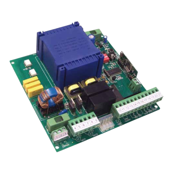
Q71A
CONTROL PANEL FOR
SWING GATES
Q71B
Control panel for swing gate automation 230Vac powered – double or single leaf
•
Streamlined programming procedure
•
Automatic setting of the obstacle detection level
•
Automatic setting of the deceleration time
•
Automatic delay setting between leafs
•
Deceleration speed adjustment
•
Pause-time adjustment
•
Outputs for safety photocells in opening and in closing
•
Outputs for START, PARTIAL OPENING and STOP push-buttons
•
Output for safety flashing light (Blinker)
•
Output for electrical lock interface (optional)
TECHNICAL FEATURES
Control Panel Dimensions
Control Panel Weight
Transformer
Blinker Power Supply
Accessories Power Supply
Working time
Pause-time
Obstacle Detection Level
Instructions Manual
135 x 140 x 60 mm
1,00 Kg
30VA 230/0 - 12 - 24Vac
24Vdc max 20W
12Vdc – 24Vdc, max 3W
ADJUSTABLE
ADJUSTABLE
AUTOMATIC
230V ac
Advertisement
Table of Contents

Related Manuals for MyGate Q71B


Summary of Contents for MyGate Q71B
- Page 1 Q71A CONTROL PANEL FOR 230V ac SWING GATES Q71B Instructions Manual Control panel for swing gate automation 230Vac powered – double or single leaf • Streamlined programming procedure • Automatic setting of the obstacle detection level • Automatic setting of the deceleration time • ...
- Page 2 WARNINGS This manual contains important information regarding personal safety. An incorrect installation or an improper use may cause serious damages to person(s) or object(s). Read carefully and pay particular attention to the safety sections marked by the symbol : Store this manual safely for future use. All wirings or operations on the control panel must be performed with the control panel disconnected from the power supply.
- Page 3 WIRING Diagram for 230V ac motor Q71 - A GIALLO - VERDE 230V ac MAINS 230V START Flashing Light 24Vac max 20W STOP Motor Electro-lock 230V 12V max 15W 12V dc /24V ac Q71B_1_2011...
- Page 4 ELECTRIC WIRINGS Please refer to the diagram in chapter 2 for a correct wiring. MOTOR wiring motor 1 → first closing and last opening leaf. motor 2 → last closing and first opening leaf. Wire motor 1 M1 to plugs 4-5-6 and motor 2 M2 to plugs 7-8-9 on J4. In case of single leaf gate, please follow motor 2 M2 instructions.
- Page 5 FLASHING LIGHT wiring You can wire a flashing light (max 20W) to plugs nr 10-11 on J1. QUICK flashing → gate OPENING • • SLOW flashing → gate CLOSING • Flashing light OFF → gate in PAUSE time PHOTOCELLS wiring Before connecting the photocells, make sure that the input voltage of the photocells is the same as the output on the control panel.
- Page 6 ELECTRICAL MAINS wiring Once all other wirings have been carried out, plug 2 (line) and plug 3 (neutral) on J5 of the control panel can be wired to the electrical mains. Selecting the OPERATING MODE Three different operating modes can be selected trough DS1 dip-switches as follows: STEP by STEP Mode A first START command makes the gate OPEN.
- Page 7 Programming of RADIO TRANSMITTERS DELETING all Radio Transmitters For your security we recommend you to delete all factory radio code memorized on the control panel: Keep P1 button on the control panel pressed until DL1 goes off (about 10 seconds). All radio codes have been deleted.
- Page 8 PAUSE-TIME setting Keep P3 button on the control panel pressed until LED DL1 lit and stays on, then release the button. • Wait for the time you want to set as pause-time and then press again P3. • • DL1 light goes off: the pause-time has been saved in the control board’s memory. •...
Need help?
Do you have a question about the Q71B and is the answer not in the manual?
Questions and answers