Advertisement
Advertisement
Table of Contents

Related Manuals for M2I XTOP15 SERIES

Summary of Contents for M2I XTOP15 SERIES
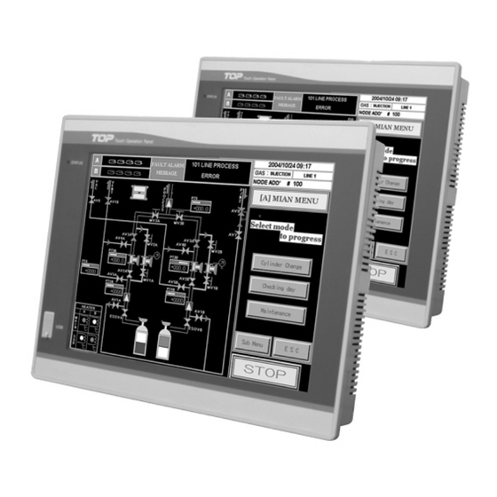
- Page 1 Main Module Users Manual XTOP15/12/10 SERIES...
-
Page 2: Installation Precautions
► Safety precautions are for using the product safely and correctly in order to prevent the accidents and danger, so make sure to follow all directions in safety precautions. ► The precautions are divided into 2 sections, ‘Warning’ and ‘Caution’. Each of the meaning is represented as follows Indicates that... -
Page 3: Design Precautions
Design Precautions Warning Install a safety circuit external to the TOP that keeps the entire system safe even when there are problems with the external power supply or the TOP module. Otherwise, serious trouble could result from erroneous output or erroneous operation. Outside the TOP, construct mechanical damage preventing interlock circuits such as emergency stop, protective circuits, positioning upper and lower limits switches and interlocking forward/reverse operation. -
Page 4: Installation
Installation 1. Caution - Please keep 100mm distance between main module and enclosure structure for maintenance and well-ventilation. - Please avoid installation on the area as follows. . Locations where the temperature changes drastically and condensation occurs . Locations where the main unit is exposed to direct sunlight, vibration or impact. . -
Page 5: Main Module Menu Summary
Main Module Menu Summary 1. Main Menu - Functions : Controller Type, Communication Protocol, Version Info., Language Setting and Time Setting * Time Data is retained minimum 1year by battery without input power voltage. 2. Communication Setting - Functions : Baud Rate, Data Bit, Parity Bit, Stop Bit, Communication Level, Station Num, Serial Timeout, Send Wait, 2Port Communication Setting, N:1 Setting and Ethernet setting. -
Page 6: Wiring Precautions
Installation Precautions Caution Use the TOP in an environment that meets the general specification contained in this manual or datasheet. Using the TOP in an environment outside the range of the general specifications could result in electric shock, fire, erroneous operation, and damage to or deterioration of the product. -
Page 7: Disposal Precaution
Trial Running Repair Precautions Warning Do not touch the terminals while power is on. Doing so could cause electric shock or erroneous operation. Switch all phases of the external power supply off when cleaning the module or retightening the terminal or module mounting screws. Not doing so could result in electric shock or erroneous operation. - Page 8 Project File Up/Download Meaning of ‘Download’ is transferring projection file data from computer to TOP main module. And ‘Upload’ is transferring data from TOP Main module to computer. Main module data will be saved up forever on flash memory of TOP main module unless overwriting.
- Page 9 Outer Dimension (Front, Rear, Side, Upper, Bottom) [Fig. 1] [Fig. 1] XTOP15 series Front Outer and Rear Outer Dimension] * XTOP15 series panel cut size : 357(W) X 286.5(H) mm [Fig. 2] [Fig. 2] XTOP12/10 series Front Outer and Rear Outer Dimension]...
- Page 10 [Fig. 3] [Fig. 3] XTOP15T Up/Down/Left/Right Outer Dimension [Fig. 4] [Fig. 4] XTOP12/10 series Up/Down/Left/Right Outer Dimension]...
-
Page 11: Serial Interface (Rs-232C)
Serial Interface (RS-232C) Feature Item Contents Protocol Half Duplex Synch. Asynchronous Communication About 15M Distance Type of Connection Control Code ASCII Code or HEXA Code Baud Rate 9600, 19200, 38400, 57600, 76800, 115200bps Data Bit 7,8bit Data Type Parity Bit None, Odd, Even Parity COM2 RS-232 Connector Pins and Signals Type... - Page 12 Serial Interface (RS-422/485) Connect main module to controller by RS-422/485 for communication. Feature Item Contents Protocol Half Duplex, 5wires Synch. Asynchronous Communication About 500M Distance Type of Connection 1:N(N≤31) Control Code ASCII Code or HEXA Code Baud Rate 9600, 19200, 38400, 57600, 76800, 115200bps Data Bit 7,8bit Data Type...
- Page 13 Title of Parts [Front View] [Rear View] [Front View] Feature Title XTOP15TX XTOP12TS XTOP10TS XTOP10TV TFT LCD 256 Color Display Resolution 1024 X 768 800 X 600 640 X 480 Screen Size 15 inch 12 inch 10.4 inch Brightness 250cd/㎡ 350cd/㎡...
-
Page 14: General Specification
USB Interface OHCI Specification Version 1.0 Communication Control/Bulk method Transfer Speed 500Kb/s –10Mb/s USB Storage (Only M2I OPTION Product, Only used FAT file Format.) Support Device USB Printer (HP PCL Level 3 ) Cable length 1.5m USB Device (Fig. 2) Item... - Page 15 Download Interface (RS232C) Download Connection RS232C In case of connecting Main Module COM1 (6P) Connector and PC 9P Connector Main Module(6P Male) PC(9P Female) (Male) < TOP232C DOWNLOAD CABLE > In case of connecting Main Module COM2 (9P) Connector and PC 9P Connector Main Module(9P Male) PC (9P Female)
- Page 16 Not used 10BaseT Blue/White Not used 10BaseT Green Brown/White Not used 10BaseT Brown Not used 10BaseT Head Office Kyonggi Venture Anyang Technical Center, Floor, 572-5, Anyang 8-Dong, Manan–Gu, Anyang–Shi, Kyonggi–Do, Korea, 430–731 TEL : (82)31-465-3366 FAX : (82)31-465-3355 http://www.m2i.co.kr M2I Corporation...
Need help?
Do you have a question about the XTOP15 SERIES and is the answer not in the manual?
Questions and answers