Table of Contents
Advertisement
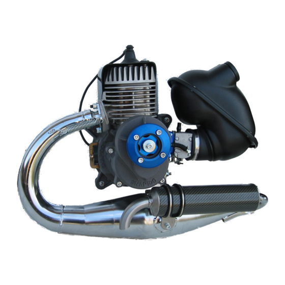
SNAP 100
Rel.3/2007
Maintenance MANUAL
All information in this publication is based the latest product information available at the time of
approval for printing.
CISCOMOTORS reserves the right to make changes at any time without notice and without
incurring any obligation.
No part of this publication may be reproduced without written permission.
Ciscomotors 2004
Advertisement
Table of Contents

Related Manuals for Ciscomotors SNAP 100


Summary of Contents for Ciscomotors SNAP 100
- Page 1 All information in this publication is based the latest product information available at the time of approval for printing. CISCOMOTORS reserves the right to make changes at any time without notice and without incurring any obligation. No part of this publication may be reproduced without written permission.
- Page 2 INDEX Pag.2 1. OPERATING INSTRUCTIONS Pag. 3 • 1.1 Basic operation Pag. 4 2. SPECIFICATIONS Pag. 6 • 2.1 Engine installation on chassis Pag. 6 • 2.2 Tecnicals characteristics Pag. 7 3. MAINTENANCE Pag. 8 • 3.1 General service information Pag.
- Page 3 1. OPERATING INSTRUCTIONS FUEL • • Vegetable oils separate from gasoline Snap 100 has a two-stroke engine that requires a gasoline-oil mixture. more easily than mineral oils, especially • Use gasoline with a pump octane in cold weather. It is advisable to use synthetic oil.
- Page 4 Pag. 4 1.1 BASIC OPERATION • In the 2-stroke motors like the Snap100, is of absolute importance the corrected carburation to avoid seizure to the piston (not covered from guarantee). Start the Engine WARNING Warm Engine Starting: • Never run the engine in an enclosed area.
- Page 5 Pag. 5 Fig.2...
- Page 6 Pag. 6 2. SPECIFICATIONS 2.1 ENGINE INSTALLATION ON CHASSIS Fig.3 1. Engine stop connector 2. Throttle cable 3. Propeller 4. Support engine 5. Manual starter CAUTION: To use antivibrating of optimal quality not superior 70s...
- Page 7 Variable Advance Spark plug standard Ngk BR9HS / B9HS Winter spark plug Ngk BR8HS / B8HS Starter Manual Carburettor Type Walbro WB32(Ciscomotors) / Dell’orto Walbro* Setting screw min Walbro* Setting screw max Trasmission Clutch Type Centrifuge 3 shoe Reduction Gears helicoidal...
- Page 8 • When tightening bolts, nuts or screw, start with the larger diameter or inner fasteners, and tighten them to the specified torque using a criss-cross pattern; • Use genuine Ciscomotors parts when maintenance your Snap100 • Clean parts in non-flammable cleaning solvent when disassembling. Lubricate any sliding surface, O-rings and seals before reassembling.
- Page 9 Pag. 9 3.3 MAINTENANCE SCHEDULE FREQUENCY INSPECT REPLACE Before and after each use All screw nuts, bolts correctly tigthen, silent-block in, and check carburation. Every 100 hours Cylinder head decarbonizing Complete piston and cleaning sponge filter Reducer’s lubricant Every 200 hours Diameter clutch, usury of the Crankshaft bearing ,bearing bell clutch, and glass wool of...
- Page 10 Pag. 10 4. STORAGE Extended storage such as for winter, requires that you take certain steps to reduce the effects of deterioration from nonuse of your Snap100. In addition necessary repairs should be made BEFORE storing your Snap100: otherwise these repairs and clean may be forgotten by the time your Snap100 is removed from storage.
- Page 11 Pag. 11 5. SPARE PARTS & EQUIPMENT 5.1 SPARE PARTS COD. DESCRIZIONE COD. DESCRIZIONE SPARK PLUG CUP SCREW GRAFT STARTER 000001.0 000040.0 SPARK PLUG CUP COOLING FAN 000001.1 000041.0 SHAFT SPARK PLUG NUT GRAFT 000002.0 000042.0 CARBON FIBER COOLING AIR DUCT CAP SCREW COOLING FAN 000003.0 000043.0...
- Page 12 Pag.12 5.2 EQUIPMENTS DESCRIPTION FLYWHEEL CLUTCH 100.200 FLYWHEEL BELL CLUTCH 100.201 SOCKETS HEX 17 m/m 100.300 SOCKETS HEX 11 m/m 100.301 SOCKETS HEX 10 m/m 100.302 MALE HEXAGON KEY 3m/m 100.310 MALE HEXAGON KEY 4m/m 100.311 MALE HEXAGON KEY 5m/m 100.312 SCREWDRIVERS-BLADE 1XL 100.315...
- Page 13 Pag.13 6. DISASSEMBLY/ASSEMBLY WARNING Modification of the motor, or removall of original equipment may make the motor unsafe. 6.1 DISASSEMBLY CARBURETTOR This section covers maintenance of the carburettor. • Repalce diaphragm fuel pump 1. Remove the 4 screw (Fig.4) 2. Remove the diaphragm 3.
- Page 14 Pag.14 6.2 DISASSEMBLY TERMICAL GROUP This section covers maintenance of the cylinder and piston.These service can be done with the engine installed in the frame. The cylinder has a nicasil coating and cannot be rebored. If it is demaged, it must be replaced. Before disassembling, clean the engine througly to keep dirt from entering the engine.Remove any gasket material from the mating surfaces.
- Page 15 Pag.15 7. Pull the exhaust with resolution (Fig.8) * Apply silicon gasket higt temperature. Fig.8 8. Remove the 4 cylinder head nuts (Fig.9) Fig.9 9. Remove the cylinder head o-ring gasket (Fig10) Fig.10 NOTE To avoid warping the cylinder head, use a criss-cross pattern to loosen each nut about ¼ turn, then remove the nuts.
- Page 16 Pag.16 DISASSEMBLY PISTON 10. Remove the piston pin clips using a pair of needle-nose pliers (Fig.11) Fig.11 11. Press the piston pin out of the piston and remove the piston.(Fig.12) Fig.12 12. Spread each piston ring end remove by lifting it up a point just oppisite the gap (Fig.13) Fig.13 CAUTION: do not damage the piston ring by spreading the ends too far.
- Page 17 Pag.17 Decarbonizing COMBUSTION CHAMBER Remove the carbon deposits from the combustion chamber. Clean the head gasket surface of any gasket material CAUTION: Use care not to scratch the combustion chamber or the head gasket surface. CYLINDER Clean carbon deposits from the exhaust. CAUTION: Do not damage the cylinder bore.
- Page 18 Pag18 INSTALLATION CYLINDER 6. Install the new cylinder gasket 7. Align each ring and gap with the piston ring pins in the ring groves (Fig.16) Fig. 16 8. Lubricate the piston with 2-stroke oil 9. Slip the cylinder over the top of the piston while compressing the rings.
- Page 19 Pag. 19 INSTALLATION CYLINDER HEAD 1. Install the new cylinder head gasket o-ring (Fig.10) 2. Install the cylinder head and nuts (Fig.9 ), tighten the nuts to the specifed torque. TORQUE : 12Nm( 1,2 kgf/m) NOTE: Tighten the cylinder head nuts in a criss-cross pattern in 2 or 3 steps INSTALLATION EXHAUST 1.
- Page 20 Pag. 20 6.3 DISASSEMBLY/ASSEMBLY STARTER 1. Remove the air duct see the chapter 6.2 2. Remove 4 screw (Fig.18) 3. Remove the nut (Fig.19) 4. Remove the pulley 5. Replace chord 3 m/m diameter CAUTION Fig.18 NOT REMOVE THE SPRING (fig.21) 1.
- Page 21 Pag. 21 6.4 DISASSEMBLY/ ASSEMBLY SILENCER 1. Remove the exhaust like chapter 6.2 2. Remove the 3 bolts and cap screw fixing silencer (Fig,.22) 3. Remove the glass wool 4. Remove the carbon deposite from the inner pipe using the wire brush 1.
- Page 22 Pag.22 6.5 DISASSEMBLY/ASSEMBLY SPONGE FILTER 1. Unscrew the filter band (fig.23) 2. Remove the airbox from the motor 3. Remove 4 screw (Fig.24) 4. Remove the sponge filter (Fig.25) Fig.23 5. Cleaning with biodegradable detergents (don’t use gasoline)and dry the sponge filter. 6.
- Page 23 Pag.23 6.6 ASSEMBLY/ DISASSEMBLY THE PROP HUB 1. Unscrew the cap screw (fig.26) 2. Unthread the hub from the reducer (Fig.27) Fig.26 1. Replace the hub on rapid graft DIN 5482 15x12 Z9 (Fig.27) 2. Tighten the cap screw with the washer in the equipment at the specified torque.
- Page 24 Pag.24 6.7 DISASSEMBLY / DISASSEMBLY THE INGNITION DISASSEMBLY 1. Disassembly the engine from the chassis 2. Remove the 4 cap screw on the ignition crankcase( Fig.18) 3. Remove the 3 cap screw of the ignition fan ( Fig.28) 4.Remove the 2 cap screw of the coil (Fig.29) Fig.28 Fig.29...
- Page 25 Pag.25 IGNITION COIL ASSEMBLY 1. Insert the coil into seat 2. Screw the 2 cap screw 3. Insert between the ignition magneto and the iron coil, some that distances them in plastic material like 0,25/0,3 mm (Fig. 30 ) 4. Tighten the cap screws at the specified torque TORQUE : 12Nm( 1,2 kgf/m) Fig.30 5.
- Page 26 Pag.26 6.8 REDUCER 1. Disassemble the prop hub like chapter 6.6 2. Disassemble the reducer from the engine and remove the 4 fixing cap screw 3. Remove the bolt from clutch bell (Fig.32) with impact tool. 4. Take off the clutch bell with the exstactor indicated (art.
- Page 27 Pag. 27 7. CARBURATION REGULATION 1. Regulation throttle cable 2. Regulation Min. gasoline 3. Regulation Max gasoline Fig.35 Standard regulation In case of problems of wrong carburetion , replace the originals levels. Screw regulation of min. 1/4 turns from all closing. (Fig.28 point 2) Screw regulation max.
- Page 28 Pag.28 8. TROUBLESHOOTING 1. THE ENGENE DOES NOT START OR IS HARD TO START CHECK POSSIBLE CAUSES SOLUTION No fuel in tank Fill tank per fueling Check if fuel is jetting to the carburettor Clogged fuel line or fuel filter Replace and clean Diaphragm fuel pump broken Replace the diaphragm (fig .27)
- Page 29 Pag.29 3. THE ENGINE VIBRATES EXCESSIVE CHECK POSSIBLE CAUSES SOLUTION Excessive wear, holder rubber Repalce (Max 70 Sh) Silent-block engine Prop out of balance Balance or replace 9. TORQUE VALUES ENGINE Thread diam x Torque ITEM pitch gf*m Cap screw propeller hub M 6 x 1,0 Spark plug M14 x 1,25...
Need help?
Do you have a question about the SNAP 100 and is the answer not in the manual?
Questions and answers