Table of Contents
Advertisement
Quick Links
Advertisement
Table of Contents

Related Manuals for FLIR VS70

Summary of Contents for FLIR VS70
- Page 1 User’s manual FLIR VS70 High definition videoscope inspection camera...
- Page 3 User’s manual FLIR VS70 #T559827; r. AE/36943/36943; en-US...
-
Page 5: Table Of Contents
Table of contents Disclaimers............. . 1 Copyright. - Page 6 Technical support for external meters ......27 FLIR Test and Measurement Limited 2 Year Warranty ... . .28...
-
Page 7: Disclaimers
1 Disclaimers 1.1 Copyright © 2016, FLIR Systems, Inc. All rights reserved worldwide. No parts of the soft- ware including source code may be reproduced, transmitted, transcribed or translated into any language or computer language in any form or by any means, electronic, magnetic, optical, manual or otherwise, without the prior written per- mission of FLIR Systems. -
Page 8: Disposal Of Electronic Waste
Please contact your FLIR Systems representative for more details. 1.5 FCC Compliance This device complies with part 15 of the FCC Rules. Operation is subject to the following two conditions: This device may not cause harmful interference. -
Page 9: Industry Canada Compliance
1 Disclaimers CAUTION Exposure to Radio Frequency Radiation. To comply with FCC/IC RF exposure compliance requirements, a separation distance of at least 20 cm must be maintained between the antenna of this de- vice and all persons. This device must not be co-located or operating in con- junction with any other antenna or transmitter. -
Page 10: Safety Information
Note Before operating the device, you must read, understand, and follow all in- structions, dangers, warnings, cautions, and notes. Note FLIR Systems reserves the right to discontinue models, parts or accesso- ries, and other items, or to change specifications at any time without prior notice. -
Page 11: Introduction
3 Introduction Congratulations on your purchase of this FLIR VS70 video borescope. This instrument is designed for use as a remote inspection device. It can be used to peer into tight spots, and record and playback real-time video and images. -
Page 12: Description
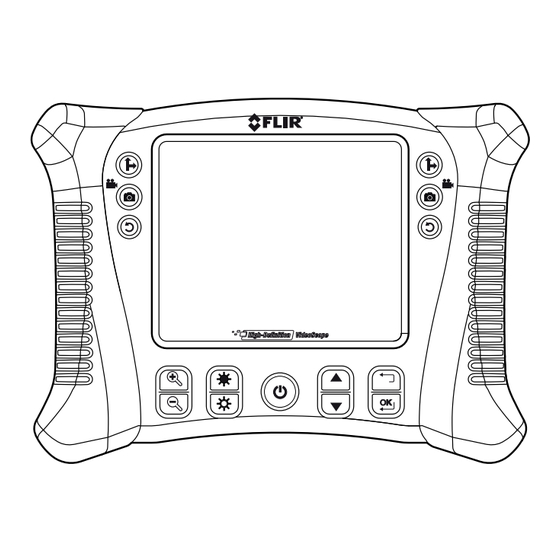
4 Description 4.1 Monitor Figure 4.1 Monitor front view Function buttons, see section 4.1.1 Function buttons, page 8. Display. #T559827; r. AE/36943/36943; en-US... - Page 13 4 Description Figure 4.2 Monitor rear view Probe connector. Rear stand. Figure 4.3 Monitor bottom view, with access cover removed USB connector. Reset button. SD card slot. Video output jack. Headset jack (audio and mic). AC adapter connector. #T559827; r. AE/36943/36943; en-US...
-
Page 14: Function Buttons
4 Description 4.1.1 Function buttons For two-camera probe, press the button to toggle between the side view and the front view camera lens. • Press the button to take a picture. • Press and hold down the button for 3 seconds to start/stop re- cording a video. -
Page 15: Articulating Probe
4 Description Indicates that a stored picture is being displayed. Indicates that a stored video is being displayed. Indicates playback of a stored video. Indicates paused playback of a stored video. 4.2 Articulating probe Figure 4.4 Articulating probe Articulation knob (up/down). Articulation knob (left/right). -
Page 16: Wireless Transmitter
4 Description 4.3 Wireless transmitter Figure 4.5 Wireless transmitter Probe connector. Light intensity buttons. Power button. AC adaptor and extension cable sockets. 4.4 Probe accessories Figure 4.6 Probe accessories Anti-snag tip. Magnet. 45° mirror. #T559827; r. AE/36943/36943; en-US... -
Page 17: Probe
4 Description 4.5 Probe Figure 4.7 Probe Camera. Shaft. Monitor connector. #T559827; r. AE/36943/36943; en-US... -
Page 18: Operation
For TWO-CAMERA PROBE, press the button to toggle between the side view and the front view camera lens. Two-camera operation requires a direct connection of the dual channel cable (VSC2-58-1FM) to the VS70 monitor. Use the buttons to zoom in and out. -
Page 19: Setup Menu
5 Operation Press and hold down the button for 3 seconds (long press) to start the video recording. The icons are displayed. While recording, you can take a picture by pressing the button (short press). Press and hold down the button for 3 seconds (long press) to stop the video recording. -
Page 20: Factory Default Profiles Menu
5.3 Factory Default Profiles menu The FLIR VS70 has two factory default profiles (Default1 and Default2) and one user profile for brightness, contrast, hue, and saturation camera settings. To ac- cess the Factory Default menu, follow this procedure: Navigate to the the VIDEO FORMAT screen in the setup menu as explained in Section 5.2. -
Page 21: Articulating Probe
5 Operation Figure 5.1 Installing probe accessories Unscrew the probe ring. Screw on the accessory. 5.5 Articulating probe The articulating probe, with an adjustable tip angle, is used for improved viewing angles and optimum inspection when the probe is inserted into the area to be ex- amined. -
Page 22: Articulating Probe-Direct Version
Note The articulating probe battery must be fully charged for wireless opera- tion. A weak battery may result in shut down of data transmission. Note The FLIR VS70 wireless operation transmits on 2.4 GHz which may inter- fere with other equipment operating on this same frequency. -
Page 23: Wireless Transmitter
Note The wireless transmitter battery must be fully charged for wireless opera- tion. A weak battery may result in shut down of the transmitter. Note The FLIR VS70 wireless operation transmits on 2.4 GHz which may inter- fere with other equipment operating on this same frequency. -
Page 24: Wireless Transmitter-Direct Version
5 Operation On the monitor, press and hold down the button for 5 seconds to switch on the monitor. In the setup menu under INPUT SOURCE, select WIRELESS. Refer to sec- tion 5.2 Setup menu, page 13. On the wireless transmitter, press and hold down the button for 5 sec- onds to switch on the transmitter. -
Page 25: Managing Stored Pictures And Videos
5 Operation 5.7 Managing stored pictures and videos 5.7.1 Viewing pictures and videos on the monitor display Press the button to access the pictures and videos in the memory. Thumbnails of the pictures and videos are displayed. The icon is dis- played on video thumbnails. -
Page 26: Deleting The Picture/Video Memory
5 Operation 5.7.3 Deleting the picture/video memory In the setup menu, select DELETE ALL. Refer to section 5.2 Setup menu, page 13. The ERASE YES/NO box appears. Press the button to select YES. Press the button to delete all files in the memory. -
Page 27: Maintenance
Note The battery will not charge properly if the monitor is switched on during the charging cycle. Note If the battery fails to charge, please contact FLIR Systems for battery re- placement service. In order to maintain IP rating, the battery must be replaced by authorized FLIR service personnel. -
Page 28: Technical Specifications
7 Technical specifications 7.1 Monitor LCD screen 145 mm (5.7″); viewable: 135 mm (5.3″) Active matrix, 640 × 480 pixels Interface Mini USB 1.1 and AV out Recording medium SD card SD memory 4 GB standard (32 GB maximum) Compression format MPEG4 Still image format JPEG (640 ×... -
Page 29: Transmitter
7 Technical specifications Dimensions (W × D × H) 241 mm × 178 mm × 70 mm (9.5″ × 7″ × 2.75″) Weight 1.57 kg (3.46 lb.), including batteries 7.2 Transmitter Frequency 2.4 GHz Data Video/audio Video system NTSC/PAL Battery 3.7 V rechargeable lithium polymer Power adaptor 100–240 V input/9 V DC output... -
Page 30: Probes And Cameras
Black Wire length 1.2 m (3.9′) 7.6 Part numbers Part number Field of view Description Wireless 2.4 GHz VS70 transmitter 56° VSA2-1-w Wireless 2-way 6 mm (0.24″) articu- lating camera with 1 m (3.3′) probe 56° Wireless 2-way articulating camera VSA2-2-w with 2 m (6.6′) probe... - Page 31 7 Technical specifications Part number Field of view Description 53° 3.9 mm (0.15″) camera with 1 m VSC3.9-1FM (3.3′) flexible probe – QVGA via SF VSC4.1-2RM 53° 4.1 mm (0.16″) camera with 2 m (6.6′) SR probe – QVGA via SF VSC5.8-1RM 56°...
- Page 32 7 Technical specifications Part number Field of view Description 72° VSC25 25 mm (0.98″) camera with FG de- tachable probe – VGA via LF 110° VSC28 28 mm (1.1″) camera with FG de- tachable probe – VGA via LF #T559827; r. AE/36943/36943; en-US...
-
Page 33: Technical Support For External Meters
8 Technical support for external meters Website http://www.flir.com/test Technical support TMSupport@flir.com Repairs Repair@flir.com Phone number +1 855-499-3662 (toll-free) #T559827; r. AE/36943/36943; en-US... -
Page 34: Flir Test And Measurement Limited 2 Year Warranty
“Product”) purchased either directly from FLIR Commer- PAIR OR REPLACEMENT OF DEFECTIVE PRODUCTS cial Systems Inc and affiliates (FLIR) or from an author- IN A MANNER, AND BY A SERVICE CENTER, AUTHOR- ized FLIR distributor or reseller that Purchaser registers IZED BY FLIR. - Page 35 7. NON-WARRANTY RETURN. Purchaser may request Any non-warranty repair of a Product is warranted for one that FLIR evaluate and service or repair a Product not cov- hundred eighty days (180) days from the date of return ered under warranty, which FLIR may agree to do in its shipment by FLIR to be free from defects in materials and sole discretion.
- Page 36 A note on the technical production of this publication This publication was produced using XML — the eXtensible Markup Language. For more information about XML, please visit http://www.w3.org/XML/ A note on the typeface used in this publication This publication was typeset using Linotype Helvetica™ World. Helvetica™ was designed by Max Miedinger (1910–1980) LOEF (List Of Effective Files) T501026.xml;...
- Page 38 Customer support http://support.flir.com Copyright © 2016, FLIR Systems, Inc. All rights reserved worldwide. Disclaimer Specifications subject to change without further notice. Models and accessories subject to regional market considerations. License procedures may apply. Products described herein may be subject to US Export Regulations. Please refer to exportquestions@flir.com with any questions.
Need help?
Do you have a question about the VS70 and is the answer not in the manual?
Questions and answers