Table of Contents
Advertisement
2716001301
The specifications of the machine and the contents of this operation manual are subject to change without prior notice due to product improvements.
Part No:
735-101
Second Edition Published in April 2014
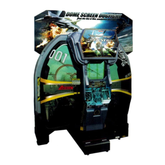
MACH STORM
Operation Manual
The actual product may differ slightly from the illustrations in this manual.
z To ensure safe operation of the machine, be sure to read this Operation Manual before use.
z
z Keep this Operation Manual in a safe place for quick access whenever needed.
z
NAMCO BANDAI Games Inc.
Advertisement
Table of Contents

Subscribe to Our Youtube Channel
Related Manuals for Bandai Namco MACH STORM


Summary of Contents for Bandai Namco MACH STORM
- Page 1 MACH STORM Operation Manual The actual product may differ slightly from the illustrations in this manual. Part No: 735-101 Second Edition Published in April 2014 z To ensure safe operation of the machine, be sure to read this Operation Manual before use.
- Page 2 Introduction Thank you very much for purchasing MACH STORM (referred to as “this machine” in this Operation Manual). This Operation Manual describes: • How to safely install, operate, move, transport, maintain and dispose of the machine. • How to make full use of the machine’s functions and operate it correctly.
-
Page 3: Safety Precautions - Be Sure To Read To Ensure Safe Operation
1. Safety Precautions – Be sure to read to ensure safe operation – Instructions to the Owner If you delegate the work for installing, operating, moving, transporting, maintaining or disposing the machine to other people, ensure that these people read the relevant sections of this operation manual carefully before starting work, and observe the corresponding precautions. -
Page 4: Critical Safety Precautions
1. Safety Precautions – Be sure to read to ensure safe operation – 1-3 Critical Safety Precautions z Should an abnormality occur, turn off the power switch immediately to stop operations. Then, be sure to disconnect the power cord plug from the outlet. Operating the machine while the abnormality persists may result in fire or accident. - Page 5 1. Safety Precautions – Be sure to read to ensure safe operation – „ The projector of this machine uses a mercury lamp as the light source. The internal pressure of this lamp increases when lit. This lamp has the characteristics shown below. Be sure to fully understand these points, and handle the lamp with sufficient care.
-
Page 6: Machine Warning Labels
1. Safety Precautions – Be sure to read to ensure safe operation – 1-4 Machine Warning Labels z The warning labels attached to the machine contain important information for ensuring safety. Be sure to observe the following. • In order to ensure that the warning labels attached to the machine are always clearly visible, install the machine in an appropriate location with ample illumination and keep the labels clean at all times. - Page 7 1. Safety Precautions – Be sure to read to ensure safe operation – • Caution sticker Projector (EXP) Part No.: 461-621 • Warning sticker Service B (EXP) Part No.: 461-539 • Danger sticker Watch your head POD (EXP) Part No.: 461-539 •...
- Page 8 1. Safety Precautions – Be sure to read to ensure safe operation – Projector unit (LVP-FD630 (V1))
-
Page 9: Table Of Contents
Table of Contents Introduction 1. Safety Precautions – Be sure to read to ensure safe operation – ..................1 1-1 Levels of Risk ...................................1 1-2 Definition of “Technician” ..............................1 1-3 Critical Safety Precautions ...............................2 1-4 Machine Warning Labels ..............................4 2. Specifications ...................................9 3. Package Contents ..................................12 4. Overall Structure (Part Names) .............................15 5. - Page 10 Table of Contents 8. Technician’s Manual – Must be performed by a technician – ....................56 8A. Installation and Assembly ..............................56 8A-1 Assembly ..................................56 8A-1-1 Assembling the Machine – Must be performed by a technician – ..............56 8A-2 Power Supply and Other Connections and Preparations.....................73 8A-2-1 Connecting the Power Cord and Ground .......................73 8A-2-2 Connecting the LAN Cable ..........................75 8A-2-3 Turning the Power Switch On ........................77 8A-2-4 Setting the Maintenance Time ........................78 8A-3 ...
-
Page 11: Specifications
2. Specifications (1) Rated power supply AC 230 V specifications: AC 230 V ±10 V AC 120 V specifications: AC 120 V ±10 V (2) Rated power consumption 200 V series: 850 W 100 V series: 860 W (3) Maximum current consumption AC 230 V specifications: 3.2 A AC 120 V specifications: 6.3 A (4) Display unit... - Page 12 2. Specifications (2) When disassembled • Front assembly Width (W) 1,780 x Depth (D) 900 x Height (H) 1,940 [mm] 1780 • Rear assembly Width (W) 1,810 x Depth (D) 985 x Height (H) 2,060 [mm] 1810...
- Page 13 2. Specifications • Projector unit Width (W) 520 x Depth (D) 480 x Height (H) 160 [mm] (LVP-FD630 (V1)) (7) Weight (1) When installed 365 kg (2) When disassembled • Front assembly 175 kg • Rear assembly 180 kg • Projector unit 10 kg...
-
Page 14: Package Contents
3. Package Contents The following items (three packages) are included when this machine is shipped. ● Make sure that all the items below are contained in the product packages. ● If any items are missing, contact your distributor. ● The packing boxes are reused when transporting the machine, so store them in a safe place and do not dispose of them. - Page 15 3. Package Contents ● Supplied Item List Name Specifications Qty. 1 Operation Manual (this manual) 2 Service key 3 Cashbox key U.S. and European specifications 4 Power cord only Not used for U.S. and European 5 LAN cable 20 m specifications 6 Remote controller for projector 7 Batteries for remote controller...
- Page 16 3. Package Contents Name Specifications Qty. 19 Lower side cover (R) 20 POP light assembly 21 LED light AC/DC 12 V 7 W 22-a POP (EXP) U.S. and European specifications 22-b POP (EXP ASIA) Asian specifications 23 POP bracket 24 Torx wrench For M5, T25 25 USB dongle 26 Clamp...
-
Page 17: Overall Structure (Part Names)
4. Overall Structure (Part Names) Front assembly Projector assembly Seat assembly Control lever assembly Coin assembly Throttle lever assembly Main power switch Game PC board Fuse Cord box assembly LAN cable* Power cord * Not required for U.S. and European Top cover specifications. -
Page 18: Delivery And Installation Conditions
5. Delivery and Installation Conditions z Install the machine according to the instructions in this Operation Manual. Failure to follow these instructions may result in fire, electric shock, injury or malfunction. z Fully insert the power cord plug into the outlet. Poor contact may generate heat and result in fire or burns. -
Page 19: Play Zone
5. Delivery and Installation Conditions 5-1-2 Play Zone z Create a play zone around the machine so that players leaving the machine do not make contact with bystanders or passersby. z When installing the machine, create a play zone approximately as shown in the figure below. -
Page 20: Required Dimensions For The Delivery Route (Such As Doors And Corridors)
5. Delivery and Installation Conditions Required Dimensions for the Delivery Route (Such as Doors and Corridors) Entryways and corridors must be larger than the dimensions noted below. z Front assembly Width (W) 1,780 x Depth (D) 900 x Height (H) 1,940 [mm] Weight 175 kg z Rear assembly... -
Page 21: Moving And Transportation
6. Moving and Transportation z Do not leave the machine on a slope. It may fall over or cause an accident. 6-1 Moving (Within the Same Floor) z Move the machine carefully to avoid damaging it. z Do not subject the machine to impact when moving it up or down a step. z Even when moving the machine only a short distance, be sure to raise the level adjusters to their highest level. -
Page 22: Transportation
6. Moving and Transportation 6-2 Transportation z Do not subject the machine to impact when lowering it. 6-2-1 Manual Transportation (Such as Carrying on Stairs) z Before transporting the machine manually, be sure to first remove the projector unit from the rear assembly (see “8B-6-1 Removing and Installing Each Part”... - Page 23 6. Moving and Transportation Before transporting the machine manually, disassemble it into each assembly by referring to “8A-1-1 Assembling the Machine” on page 56. Raise the level adjusters to their highest level. Remove the molded covers. Disassemble the machine into the front and rear assemblies. Attach the rear joint frame to the rear assembly.
-
Page 24: Loading To And Unloading From A Vehicle
6. Moving and Transportation 6-2-2 Loading to and Unloading from a Vehicle z Before transporting the machine manually, be sure to disassemble it into the front and rear assemblies, remove the projector unit from the rear assembly, and attach the rear joint frame to the rear assembly. -
Page 25: Transportation Using A Vehicle
6. Moving and Transportation 6-2-3 Transportation Using a Vehicle z When transporting the machine on a vehicle, secure the machine firmly so that it does not move during vehicle transport. Failure to secure the machine may result in an accident. z Do not subject the machine to impact when lowering it. -
Page 26: Operation
7. Operation z Should an abnormality occur, turn off the main power switch immediately to stop operations. Then, be sure to disconnect the power cord plug from the outlet. z Operating the machine while the abnormality persists may result in fire or accident. z Dust accumulating on the power cord plug may result in fire. -
Page 27: Pre-Operation Inspection
7. Operation 7-1 Pre-operation Inspection 7-1-1 Safety Inspection Check the points below before starting machine operations. If there is an abnormality, resolve it by referring to “8B-2 Troubleshooting” on page 85. z Before operating the machine, check the following locations. This is required to prevent accident or injury. -
Page 28: Function Inspection (After Power On)
7. Operation 7-1-2 Function Inspection (After Power On) Inspect the following points after turning on the power switch. If you discover an abnormality, turn off the power switch immediately to stop operations. Then, disconnect the power cord plug from the outlet and contact your distributor. • Is any part of the power cord or plug abnormally hot? • Does touching the machine give a tingling electric shock? • Is there a burning smell, abnormal noise or vibration? -
Page 29: Playing The Game
7. Operation 7-2 Playing the Game Missile button Machine gun button The game ends when the number of credits runs out (1 credit = 1 stage) or when the endurance gauge reaches 0. 7-2-1 Game Flow Control lever Turn right Dive [Operation Method during Game Play] Throttle lever... - Page 30 7. Operation [RETRY] When the retry function is set to ON and a mission is failed, the player can play the same mission again from the start by inserting coins equal to the required additional number of credits. [EXTRA MISSION] When the extra mission function is set to ON and a mission is successfully completed, the player can challenge an extra mission by inserting coins equal to the required additional number of credits.
-
Page 31: Adjustment
7. Operation 7-3 Adjustment 7-3-1 Turning the Power Switch On Turn on the main power switch located on the front of the front assembly. If the machine does not start up correctly, the system power switch may not be set to ON. Check the system power switch by referring to “7-3-2 Adjustment Switches” on page 30. -
Page 32: Adjustment Switches
7. Operation 7-3-2 Adjustment Switches The adjustment switches are located inside the machine. (f) Door switch (a) Service switch (red) サービス SW (service) (c) Select switch セレクト システム SW テスト パワー (select) (test) (system) (d) Enter switch (green) power エンター SW (enter)... -
Page 33: Test Mode
7. Operation 7-4 Test Mode 7-4-1 Description of the Main Menu Screen (MENU) Use the service key to unlock and open the service door, and set the Test switch to ON. The MENU screen appears on the screen. Flip the Select switch up or down to select the item. The selected item blinks. Press the Enter switch to enter the selected item. When the selection is entered, the display changes to the detailed information for the selected item. - Page 34 7. Operation Reference Item Description section LEFT CREDIT Number of unused credits immediately before switching – to Test mode USE CREDIT Number of credits being used by the player during game – play immediately before switching to Test mode...
-
Page 35: Game Cost Settings (Coin Options)
7. Operation 7-4-2 Game Cost Settings (COIN OPTIONS) This screen is used to make various changes to the cost settings such as the game cost settings. In the MENU screen, select COIN OPTIONS and press the Enter switch. The COIN OPTIONS screen appears. Flip the Select switch up or down to select the item. The selected item blinks. COIN OPTIONS [DEFAULT IN GREEN] GAME COST... -
Page 36: Game Contents Settings (Game Options)
7. Operation 7-4-3 Game Contents Settings (GAME OPTIONS) This screen is used to make various game contents settings. In the MENU screen, select GAME OPTIONS and press the Enter switch. The GAME OPTIONS screen appears. Flip the Select switch up or down to select the item. The selected item blinks. GAME OPTIONS [DEFAULT IN GREEN] DIFFICULTY C(NORMAL) NO DEAD MODE... -
Page 37: Input/Output Test Of Switches (I/O Test)
7. Operation 7-4-4 Input/Output Test of Switches (I/O TEST) This screen is used to test the switches and other items. In the MENU screen, select I/O TEST and press the Enter switch. The I/O TEST screen appears. Flip the Select switch up or down to select the item to be changed. I/O TEST ( a) I/F CALIBRATION ( b) SWITCH TEST... - Page 38 7. Operation I/F CALIBRATION This screen is used to initialize the controls (levers). In the I/O TEST screen, select I/F CALIBRATION and press the Enter switch. The I/F CALIBRATION screen appears. I/F CALIBRATION THROTTLE LEVER CONTROL LEVER Y: 7F40 X: 8680 Y: 8840 [STEP 1] Tilt the right and left levers as far as they will go in each direction. [STEP 2] Take your hands off the right and left levers. [STEP 3] Press the service switch to complete the initialization process.
- Page 39 7. Operation SWITCH TEST This screen is used to test each switch and control. In the I/O TEST screen, select SWITCH TEST and press the Enter switch. The SWITCH TEST screen appears. Flip the Select switch up or down to select the item to be tested. SWITCH TEST [ON: RED ] ( a) COIN INPUT1 ( b) COIN INPUT2 ( c ) SERVICE...
- Page 40 7. Operation OUTPUT TEST This screen is used to check the fan, control lever vibration, and back lamp operation. In the I/O TEST screen, select OUTPUT TEST and press the Enter switch. The OUTPUT TEST screen appears. Flip the Select switch up or down to select the item to be changed. OUTPUT TEST [ON: RED ] ( a ) FRONT FAN ( b )
- Page 41 7. Operation PROJECTOR TEST This screen is used to check the projector lamp operation time and current status. In the I/O TEST screen, select PROJECTOR TEST and press the Enter switch. The PROJECTOR TEST screen appears. PROJECTOR TEST ( a ) STATUS ( b ) STATE 2 TURN ON ( c ) LAMP TIME 285 HOUR(S) PANEL TIME ------ HOUR(S) ( d )
- Page 42 7. Operation CAMERA TEST This screen is used to check that the image taken by the camera can be displayed. In the I/O TEST screen, select CAMERA TEST and press the Enter switch. The CAMERA TEST screen appears. Flip the Select switch up or down to select the item to be changed. The selected item blinks. CAMERA TEST TAKE EXIT...
-
Page 43: Projector Test (Monitor Test)
7. Operation 7-4-5 Projector Test (MONITOR TEST) This screen is used to make various monitor (projector) adjustments. In the MENU screen, select MONITOR TEST and press the Enter switch. The MONITOR TEST screen appears. Flip the Select switch up or down to select the item to be changed. The selected item blinks. MONITOR TEST ( a) GRADATION PATTERN ( b) VIEW ANGLE ADJUST PATTERN... -
Page 44: Sound Test
7. Operation 7-4-6 SOUND TEST z Set the cabinet volume within the range that allows the player to hear alarms and warning announcements within the operating facility. This screen is used to set the sound volume and to request sounds (stereo check). In the MENU screen, select SOUND TEST and press the Enter switch. The SOUND TEST screen appears. -
Page 45: Displaying Game Data (Bookkeeping)
7. Operation 7-4-7 Displaying Game Data (BOOKKEEPING) This screen displays the operating time, play count and other game related data. In the MENU screen, select BOOKKEEPING and press the Enter switch. The BOOKKEEPING screen appears. Flip the Select switch up or down to select the item to be changed. The selected item blinks. BOOKKEEPING 04/Oct/2013 FRI 11:17:26 (UTC) SINCE... - Page 46 7. Operation ERROR LOG This screen is used to check the error history. In the BOOKKEEPING screen, select ERROR LOG and press the Enter switch. The ERROR LOG screen appears. Flip the Select switch up or down to select the item to be changed. The selected item blinks. Up to 20 of the most recent errors along with the date and time of occurrence can be viewed with 10 errors per page. The most recent error appears at the top of ERROR LOG (1/2), and the oldest error appears at the bottom of ERROR LOG (2/2).
-
Page 47: Other Options (Others)
7. Operation 7-4-8 Other Options (OTHERS) This screen is used to initialize various settings. In the MENU screen, select OTHERS and press the Enter switch. The OTHERS screen appears. Flip the Select switch up or down to select the item to be changed. The selected item blinks. OTHERS [DEFAULT IN GREEN] ( a) DAC100-2-NA-MPRO-A01 (2013-09-30 16:49:22) ( b) CLOCK 04/Oct/2013 FRI 11:24:33 (UTC) ( c ) 271611-100001 ( d) - Page 48 7. Operation Setting the Clock (CLOCK SETTING) Used to set the clock. The clock can be set only when the clock is incorrect at machine start-up. (The clock can be set anytime when using the offline version of the software.) When using the online version of the software, this option is not available in the normal test mode. (The option is not displayed.) In the OTHERS screen, select CLOCK SETTING and press the Enter switch. The CLOCK SETTING screen appears.
- Page 49 7. Operation Setting the Maintenance Time (MAINTENANCE TIME SETTING) This screen is used to set the maintenance time at which the game PC board is automatically restarted in order to reduce the load on the game PC board when operating the machine continuously for long times. In the OTHERS screen, select MAINTENANCE TIME SETTING and press the Enter switch. The MAINTENANCE TIME SETTING screen appears. Flip the Select switch up or down to select the item. The selected item blinks. MAINTENANCE TIME SETTING CLOCK 04/Oct/2013 FRI 11:10:00(UTC) MAINTENANCE TIME 07:00(UTC) HOUR MINUTE EXIT...
-
Page 50: Network Status
7. Operation 7-4-9 NETWORK STATUS * This screen is not used for U.S. and European specifications. This screen is used to check the network status. * The settings on this page are available only when using the online version of the software. In the MENU screen, select NETWORK STATUS and press the Enter switch. The NETWORK STATUS screen appears. Flip the Select switch up or down to select the item to be changed. The selected item blinks. NETWORK STATUS PCB ID ABGN-1100001... - Page 51 7. Operation Press the Enter switch to enter the selected item. Select EXIT and press the Enter switch to return to the MENU screen.
-
Page 52: Nbline Points
7. Operation 7-4-10 NBLINE POINTS * This screen is not used for U.S. and European specifications. This screen is used to check the NBLINE points. * The settings on this page are available only when using the online version of the software. In the MENU screen, select NBLINE POINTS and press the Enter switch. The NBLINE POINTS screen appears. Flip the Select switch up or down to select the item to be changed. The selected item blinks. NBLINE POINTS PCB ID ABGN-1100001... -
Page 53: About The Network
7. Operation 7-5 About the Network * Connection to a network is not required for U.S. and European specifications. When using the online version of the software, this machine requires connection to the network (NBLINE) to operate. (*1) When communication trouble or other trouble occurs in the network connection, the machine operates in offline mode. The machine can be operated for 240 hours (10 days) (*2) in the offline condition to enable game play even when network trouble occurs for short periods. However, when this time limit is exceeded, new games cannot be played. In this case, “22-1 ERROR” is displayed on the screen. (When the limit of 240 hours (10 days) is exceeded during game play, game play can continue until the game is over.) To enable game play again, resolve the network trouble and connect to NBLINE. (*3) *1 T he network connection status can be checked in Test mode. (See “7-4-9 NETWORK STATUS” on page... -
Page 54: Cleaning
7. Operation 7-6 Cleaning z Do not use thinner, benzene, gasoline or other organic solvents. This may degrade the materials. Cleaning the Screen Surface Wipe away any dirt or dust on the screen surface using a soft cloth moistened with a small amount of water, then wipe dry using a dry soft cloth. - Page 55 7. Operation Cleaning the Projector Filters z Regularly clean the projector filters approximately once per week. Dust and dirt accumulating on the filters may prevent adequate ventilation and result in a projector error. Remove the filter F and filter R. (See “8B-6-1 (3) Replacing the Filter F (Projector)” on page 150 and “8B-6-1 (4) Replacing the Filter R (Projector)” on page 151.) Clean the dust and dirt from the filter F and filter R surfaces. Wash with water and allow to dry thoroughly, or use a vacuum cleaner, being careful not to suck the filter into the vacuum cleaner.
-
Page 56: Projector Lamp (Lamp Unit) Life
7. Operation 7-7 Projector Lamp (Lamp Unit) Life It is recommended to replace the projector lamp (lamp unit) promptly to avoid inconveniencing players or other customers. The projector lamp (lamp unit) is a consumable part, and may stop lighting up or the brightness may drop before the lamp reaches the end of its life. The lamp life time noted below is approximate, and is not a guaranteed value. z Projector model number: LVP-FD630 (V1) Lamp life: 5,000 hours When the lamp reaches the end of its life, the projector stops and the screen goes blank. The game cannot be operated thereafter until the projector lamp (lamp unit) is replaced. In order to avoid this situation, be sure to... -
Page 57: 24-Hour Continuous Operation
7. Operation 7-8 24-Hour Continuous Operation This machine has a maintenance function that automatically restarts the game PC board in order to reduce the load on the game PC board when operating the machine continuously for long times. * The restart time is approximately 3 minutes. When operating the machine continuously for long times such as 24-hour operation, refer to “(2) Setting the Maintenance Time (MAINTENANCE TIME SETTING)” on page 47 and set the maintenance time. * T he game PC board automatically restarts (approximately 3 minutes) when Attract mode is entered next after the maintenance time is reached, so set the time to a time period during which there is usually little game play. z There is no need to use this function when the power is turned on and off once or more per day, but set the maintenance time to a time period other than during operating hours to prevent the game PC board from restarting during operating hours. -
Page 58: Technician's Manual - Must Be Performed By A Technician
8. Technician’s Manual – Must be performed by a technician – ※Chapter 8 (page 56 to page 164) of the Operation Manual is for use by service technicians only. The procedures described in these pages must only be performed by qualified service personnel. 8A. - Page 59 8A. Installation and Assembly – Must be performed by a technician – Remove the two flange socket bolts (M3 x 10) from the game PC board and remove the PCB duct. Flange socket bolt (M3 x 10) PCB duct Game PC board Connect the four connectors from the front assembly side to the connectors of the rear assembly, and lead the two connectors from the rear assembly side into the front assembly. Connect these four connectors to the panel mount of the rear assembly.
- Page 60 8A. Installation and Assembly – Must be performed by a technician – Connect the two connectors led into the front assembly to the connectors on the game PC board panel. Then, insert the USB dongle into the USB 3 slot. Projector communication USB dongle Serial 1 (Connect to SERIAL1) Game PC board Projector video VIDEO 1 (Connect to DVI1) Front assembly Connector Rear assembly Connector USB dongle Bundle the rear side cables together using the clamps bundling the front side cables.
- Page 61 8A. Installation and Assembly – Must be performed by a technician – Push the front assembly and rear assembly together and use two supplied flange socket bolts (M8 x 16) to temporarily secure the bracket on the rear side of the opened door. Bracket Door Flange socket bolt (M8 x 16) z When pushing the front and rear assemblies together, the cover bracket protrusions of the rear assembly may contact the front assembly depending on the floor condition or other factors, so push strongly while being careful not to pinch your hands or other items.
- Page 62 8A. Installation and Assembly – Must be performed by a technician – Use six supplied flange socket bolts (M8 x 16) to temporarily secure the supplied side joint (L). Then, use six supplied flange socket bolts (M8 x 16) to temporarily secure the supplied side joint (R). Side joint (L) Temporarily secure using flange socket Side joint (L) (The bolts (M8 x 16) opposite side is the side joint (R).) Slot Rear assembly door side Front assembly dome side...
- Page 63 8A. Installation and Assembly – Must be performed by a technician – Removing the Rear Joint Frame Remove the six flange socket bolts (M8 x 16), and remove the rear joint frame. z The rear joint frame is a required part during disassembly and transportation, so be sure to keep it together with the bolts in a safe place. Rear assembly Flange socket bolt (M8 x 16) Rear joint frame...
- Page 64 8A. Installation and Assembly – Must be performed by a technician – Use four supplied Torx bolts (black) (M5 x 12) to install the supplied lower side cover (R). Torx bolt (black) (M5 x 12) Lower side cover (R) Hook the slot at the top of the supplied side cover (L) onto the hook, then install the side cover (L) and secure it using five supplied Torx bolts (silver) (M5 x 12) and two flat washers (ø5 x 16). Perform the same procedure to also install the side cover (R). When installing the side cover (R), Hook insert it under the top cover. Slot in side cover (R) Top cover Hook Side cover (R)
- Page 65 8A. Installation and Assembly – Must be performed by a technician – Level Adjuster Adjustment After the machine has been installed in accordance with “5-1 Installation Conditions” on page 16, lower the seven level adjusters until the casters are at a height of approximately 5 mm from the floor. Caster Approximately 5 mm Level adjuster...
- Page 66 8A. Installation and Assembly – Must be performed by a technician – Installing the Projector Unit z The projector unit weighs approximately 10 kg. Be very careful when performing installation. z The projector unit packing materials are used when moving and transporting the projector unit, so do not dispose of these materials.
- Page 67 8A. Installation and Assembly – Must be performed by a technician – Remove the projector unit from the packing box, hold it by the handles with the lens facing downward, and hook the handles onto the fixtures on both sides of the projector case. z Be very careful not to bump the lens part. z Install the projector unit with the same serial number as the rear assembly. If a projector unit with a different serial number is installed, the video position on the dome screen may be offset.
- Page 68 8A. Installation and Assembly – Must be performed by a technician – Connect the three connectors to the projector. Connector Insert the connectors aligned as shown in the figure below. Front side Front side Projector unit Lift up the projector unit and push it back into the projector case, being careful not to pinch the cables. Then, hook the front side of the handles onto the fixtures to secure the projector unit. Hook here Handle Projector unit...
- Page 69 8A. Installation and Assembly – Must be performed by a technician – z When installing the LVP-FD630 (V1), arrange the cables so that they pass over the top of the projector unit. Cables Use two supplied flange socket bolts (M6 x 14) to secure the projector unit to the fixtures on both sides of the projector case. Projector case Flange socket bolt (M6 x 14) Projector unit...
- Page 70 8A. Installation and Assembly – Must be performed by a technician – Close the front lid and projector cover by reversing the procedure. Support the front lid with your right hand and press the lock with the finger of your left hand to release the lock. Lock (Push to release) z Be careful not to touch the projector lens with your bare hands. Fingerprints or other dirt may prevent images from being projected properly.
- Page 71 8A. Installation and Assembly – Must be performed by a technician – Installing the POP Display z Removing the POP display requires standing at an elevated height. Prepare an appropriate footstool and be careful when working. Working in an unnatural body posture may result in injury or machine damage.
- Page 72 8A. Installation and Assembly – Must be performed by a technician – Secure the POP bracket to the rear assembly with two Torx bolts (silver) (M5 x 12). Torx bolt (silver) (M5 x 12) Illustration surface POP bracket Rear assembly...
- Page 73 8A. Installation and Assembly – Must be performed by a technician – Installing the POP Light Assembly z Removing the POP light assembly requires standing at an elevated height. Prepare an appropriate footstool and be careful when working. Working in an unnatural body posture may result in injury or machine damage.
- Page 74 8A. Installation and Assembly – Must be performed by a technician – Install the previously removed POP light cover with three Torx bolts (silver) (M5 x 12). Torx bolt (silver) (M5 x 12) POP light cover Lift up the POP light assembly to the top of the rear assembly and connect the connector. z When lifting up the POP light assembly to the top of the rear assembly, hold the POP light assembly with the LED lights facing upward and do not subject it to strong impact.
-
Page 75: Power Supply And Other Connections And Preparations
8A. Installation and Assembly – Must be performed by a technician – 8A-2 Power Supply and Other Connections and Preparations 8A-2-1 Connecting the Power Cord and Ground z Connect the ground wire of the 3P plug to the ground. Failure to connect the ground wire may result in electric shock in the event of electrical leakage. - Page 76 8A. Installation and Assembly – Must be performed by a technician – Connecting the power cord to the machine Insert the supplied power cord clamp above the power supply inlet. Connect the power cord plug to the power supply inlet of the machine, then secure it with the clamp as shown in the figure below to prevent accidental disconnection. Power cord Clamp Cord box assembly Insert the power cord plug into Insert the AC cord clamp into the hole the power supply inlet.
-
Page 77: 2-2 Connecting The Lan Cable
8A. Installation and Assembly – Must be performed by a technician – 8A-2-2 Connecting the LAN Cable * This task is not required for U.S. and European specifications. z In order to avoid electric shock, accident or injury to yourself or others as well as damage to the electronic circuits, be sure to turn off the power switch before starting this task. z Lay out the LAN cable so that it will not cause players, bystanders or passersby to trip over it. - Page 78 8A. Installation and Assembly – Must be performed by a technician – Connection diagram z In order to avoid electric shock, accident or injury to yourself or others as well as damage to the electronic circuits, be sure to turn off the power switch before starting this task. Refer to the figure below and connect the LAN cable connected to the cabinet assembly to an NBLINE router and connected to NBLINE or to an open port of an NBLINE compatible switching hub.
-
Page 79: 2-3 Turning The Power Switch On
8A. Installation and Assembly – Must be performed by a technician – 8A-2-3 Turning the Power Switch On z When turning the power off and then on again, do not turn the power back on immediately, and be sure to observe the following condition. • When using the system power switch Turn off the switch, wait for 30 seconds or more, and then turn on the switch again. -
Page 80: 2-4 Setting The Maintenance Time
8A. Installation and Assembly – Must be performed by a technician – 8A-2-4 Setting the Maintenance Time This machine has a function that automatically restarts the game PC board in order to reduce the load on the game PC board when operating the machine continuously for long times. At the default this maintenance time is set to AM7:00 UTC (coordinated universal time), so refer to “(2) Setting the Maintenance Time (MAINTENANCE TIME SETTING)” on page 47 and change the setting to a time that will have little effect even if the game PC board is restarted during the shop operating hours. * It is recommended to set this maintenance time to a time other than during operating hours. -
Page 81: Post-Installation Checks
8A. Installation and Assembly – Must be performed by a technician – 8A-3 Post-Installation Checks H as the machine been installed in conformance with the installation conditions? (See “5-1 Installation Conditions” on page 16.) Are the power capacity conditions met? Has the ground wire been installed? H as the power cord been installed using cable molding or other means so that players and other customers do not trip over it? Are images projected over the entire dome screen (all the way to the edges)? (See “8B-6-2 Adjusting the Projector Position” on page 155.) -
Page 82: Disassembly (When The Delivery Route Has A Low Ceiling)
8A. Installation and Assembly – Must be performed by a technician – 8A-4 Disassembly (When the Delivery Route has a Low Ceiling) 8A-4-1 Removing the Top Cover – Must be performed by a technician – The height after the top cover is removed is 2,060 mm. z In order to avoid electric shock, accident or injury to yourself or others as well as damage to the electronic circuits, be sure to turn off the main power switch before starting this task. - Page 83 8A. Installation and Assembly – Must be performed by a technician – Remove the six Torx bolts (silver) (M5 x 8) and six flat washers (ø16 x ø5), and remove the acrylic panel. Torx bolt (silver) (M5 x 8) Flat washers (ø16 x ø5) Acrylic panel Remove the ten Torx bolts (M5 x 12) and the flat washer (ø16 x ø5) and remove the top cover. Torx bolt Top cover (M5 x 12) Torx bolt (M5 x 12) Flat washer (ø16 x ø5)
- Page 84 8A. Installation and Assembly – Must be performed by a technician – Disconnect the connector of the LED module (white). Connector Loosen the upper two hexagon socket head bolts (with flat and spring washers) (M6 x 16), and remove the lower two hexagon socket head bolts (with flat and spring washers) (M6 x 16). Remove the two Torx bolts (silver) (M5 x 12), and remove the top cover. Lift up slightly and remove. Top cover Loosen these two hexagon socket head bolt (with flat and spring washers) (M6 x 16).
-
Page 85: Service
8B. Service – Must be performed by a technician – – Must be performed by a technician – 8B. Service z In order to avoid electric shock, accident or injury to yourself or other people, be sure to turn off the power switch before performing service work (such as repairs or correcting malfunctions). - Page 86 8B. Service – Must be performed by a technician – – Must be performed by a technician – Greasing the Lever Assemblies • Clean off the old grease every six months and apply fresh silicon grease (Shin-Etsu Chemical Co., Ltd G-40M or equivalent product) to the stainless steel part, spring stopper and shaft. Also reapply grease when the lever operation becomes stiff.
-
Page 87: Troubleshooting
8B. Service – Must be performed by a technician – 8B-2 Troubleshooting 8B-2-1 Machine – Must be performed by a technician – Symptom Main cause Solution Reference page • T he machine does not • T he USB dongle is not • I nsert the USB dongle. -
Page 88: 2-2 Projector Assembly - Must Be Performed By A Technician
8B. Service – Must be performed by a technician – 8B-2-2 Projector Assembly – Must be performed by a technician – Symptom Main cause Solution Reference page • I mages are not • A projector unit connector is • I nsert the connector securely. Page 66 displayed. -
Page 89: 2-3 Throttle And Control Lever Assemblies - Must Be Performed By A Technician
8B. Service – Must be performed by a technician – Symptom Main cause Solution Reference page • “ LAMP EXCHANGE” • T he projector lamp is • W hen the lamp operation time Page 54 is displayed on the nearing the end of its life. exceeds 4,750 hours, this message Page 144 left edge of the dome... -
Page 90: 2-4 Seat Assembly - Must Be Performed By A Technician
8B. Service – Must be performed by a technician – 8B-2-4 Seat Assembly – Must be performed by a technician – Symptom Main cause Solution Reference page • T here is no sound • T he volume setting is low. • S et the appropriate volume. -
Page 91: Error Displays - Must Be Performed By A Technician
8B. Service – Must be performed by a technician – 8B-3 Error Displays – Must be performed by a technician – Error Display * If the error display remains on the screen after performing the appropriate solution, set the Test switch to ON and then OFF again to cancel the error display. - Page 92 8B. Service – Must be performed by a technician – Projector Errors When the projector lamp has burned out, the back lamp lights up red. When the screen is blank and the back lamp is not lit up red, there may be a problem with the projector. Request a technician to solve the problem.
-
Page 93: Network Trouble
8B. Service – Must be performed by a technician – – Must be performed by a technician – 8B-4 Network Trouble When using the online version of the software with the machine not connected to the network, some limits are applied even if there are no mechanical abnormalities. -
Page 94: Removing And Installing Assemblies And Parts
8B. Service – Must be performed by a technician – – Must be performed by a technician – 8B-5 Removing and Installing Assemblies and Parts 8B-5-1 Machine – Must be performed by a technician – Removing and Installing the Game PC Board – Must be performed by a technician – z In order to avoid electric shock, accident or injury to yourself or others as well as damage to the electronic circuits, be sure to turn off the power switch before starting this task. - Page 95 8B. Service – Must be performed by a technician – – Must be performed by a technician – Remove the two flange socket bolts (M3 x 10) from the game PC board and remove the PCB duct. Then, remove the two Phillips pan head screws (with flat and spring washers) (M3 x 6) from the PCB duct and attach them to the game PC board. Flange socket bolt (M3 x 10) PCB duct Game PC board Attach the two Phillips pan head screws Phillips pan head screws...
- Page 96 8B. Service – Must be performed by a technician – – Must be performed by a technician – z When installing, follow the indications on the game PC board and connect the connectors correctly. Projector communication SERIAL 1 No connection JV I/O (Connect to SERIAL 1) (milky white USB cable)
- Page 97 8B. Service – Must be performed by a technician – – Must be performed by a technician – Remove the game PC board. Use the handles as guides and hold the game PC board firmly with both hands when removing and installing the game PC board. Game PC board ES3 (X) base C Be very careful of the sheet metal...
- Page 98 8B. Service – Must be performed by a technician – – Must be performed by a technician – Remove the ten Phillips pan head screws (with flat and spring washers) (M4 x 10) and remove the ES3 (X) base A, ES3 (X) base B and NA-JV (S) PC board. NA-JV (S) PC board Phillips pan head screws (with flat and spring washers) (M4 x 10) ES3 (X) base B Game PC board Phillips pan head screws ES3 (X) base A...
- Page 99 8B. Service – Must be performed by a technician – – Must be performed by a technician – Replacing the NA-JV (S) PC Board – Must be performed by a technician – z In order to avoid electric shock, accident or injury to yourself or others as well as damage to the electronic circuits, be sure to turn off the power switch before starting this task.
- Page 100 8B. Service – Must be performed by a technician – – Must be performed by a technician – Open the two clamps and disconnect the Faston terminal and four connectors connected to the NA-JV (S) PC board. Game PC board Clamp Power cord Connector NA-JV (S) PC board Connector 3 connectors Faston terminal Remove the five Phillips pan head screws (with flat and spring washers) (M3 x 8) and remove the NA-JV (S) PC board. NA-JV (S) PC board Game PC board Phillips pan head screws (with flat and spring washer)
- Page 101 8B. Service – Must be performed by a technician – – Must be performed by a technician – Replacing the 5.1CH AMP PC Board – Must be performed by a technician – z In order to avoid electric shock, accident or injury to yourself or others as well as damage to the electronic circuits, be sure to turn off the power switch before starting this task.
- Page 102 8B. Service – Must be performed by a technician – – Must be performed by a technician – Disconnect the six connectors, remove the five Phillips pan head screws (with flat and spring washers) (M3 x 8) and remove the 5.1CH AMP PC board. Phillips pan head screws (with flat and spring washers) (M3 x 8) Connector 5.1CH AMP PC board Connector...
- Page 103 8B. Service – Must be performed by a technician – – Must be performed by a technician – Removing and Installing the Power Panel Assembly – Must be performed by a technician – z In order to avoid electric shock, accident or injury to yourself or others as well as damage to the electronic circuits, be sure to turn off the power switch before starting this task.
- Page 104 8B. Service – Must be performed by a technician – – Must be performed by a technician – Replacing the Fan – Must be performed by a technician – z In order to avoid electric shock, accident or injury to yourself or others as well as damage to the electronic circuits, be sure to turn off the power switch before starting this task.
- Page 105 8B. Service – Must be performed by a technician – – Must be performed by a technician – Replacing and Installing the Control Lever Assembly – Must be performed by a technician – z In order to avoid electric shock, accident or injury to yourself or others as well as damage to the electronic circuits, be sure to turn off the power switch before starting this task.
- Page 106 8B. Service – Must be performed by a technician – – Must be performed by a technician – Replacing the Control Lever Analog Interface – Must be performed by a technician – z In order to avoid electric shock, accident or injury to yourself or others as well as damage to the electronic circuits, be sure to turn off the power switch before starting this task.
- Page 107 8B. Service – Must be performed by a technician – – Must be performed by a technician – To install, perform the procedure in reverse. z When installing the analog interface, align the flat surface of the analog interface shaft with the position of the D-shaped hole. z After replacement, be sure to perform initialization.
- Page 108 8B. Service – Must be performed by a technician – – Must be performed by a technician – Replacing the Control Lever Switch (Micro Switch) – Must be performed by a technician – z In order to avoid electric shock, accident or injury to yourself or others as well as damage to the electronic circuits, be sure to turn off the power switch before starting this task.
- Page 109 8B. Service – Must be performed by a technician – – Must be performed by a technician – Remove the four special Phillips pan head screws (M2.3 x 12), four spring washers and the Phillips pan head screw (with flat and spring washers) (M4 x 8), and remove the switches and clamps. Special Phillips pan head screw (M2.3 x 12) Phillips pan head screw Spring washer (M2.3) (with flat and spring washers) (M4 x 8) Lever grip B Clamp...
- Page 110 8B. Service – Must be performed by a technician – – Must be performed by a technician – To install, perform the procedure in reverse. Arrange the cable by wrapping it around the shaft one time in the clockwise. Shaft Front side z Arrange the cable by wrapping it around the shaft one time in the clockwise direction starting from the analog interface side.
- Page 111 8B. Service – Must be performed by a technician – – Must be performed by a technician – Replacing the Lever Switch (Machine Gun Button) – Must be performed by a technician – z In order to avoid electric shock, accident or injury to yourself or others as well as damage to the electronic circuits, be sure to turn off the power switch before starting this task.
- Page 112 8B. Service – Must be performed by a technician – – Must be performed by a technician – (10) Replacing the Lever Switch (Missile Button) – Must be performed by a technician – z In order to avoid electric shock, accident or injury to yourself or others as well as damage to the electronic circuits, be sure to turn off the power switch before starting this task.
- Page 113 8B. Service – Must be performed by a technician – – Must be performed by a technician – (11) Replacing the Control Lever Vibration Motor – Must be performed by a technician – z In order to avoid electric shock, accident or injury to yourself or others as well as damage to the electronic circuits, be sure to turn off the power switch before starting this task.
- Page 114 8B. Service – Must be performed by a technician – – Must be performed by a technician – Rotate the weight, remove the two Phillips pan head screws (M2.3 x 2.5) and remove the vibration motor. Replace with a new vibration motor by reversing the procedure. Vibration motor Motor bracket Rotate the weight to remove the screws. Phillip pan head screws (M2.3 x 2.5) Wind the harness of the new vibration motor around the ferrite core one time, attach the core spacer to the ferrite core, and install the vibration motor, ferrite core and core spacer to the...
- Page 115 8B. Service – Must be performed by a technician – – Must be performed by a technician – (12) Replacing the Spring or Spring Stopper – Must be performed by a technician – z In order to avoid electric shock, accident or injury to yourself or others as well as damage to the electronic circuits, be sure to turn off the power switch before starting this task.
- Page 116 8B. Service – Must be performed by a technician – – Must be performed by a technician – (13) Replacing the Rubber Cover – Must be performed by a technician – z In order to avoid electric shock, accident or injury to yourself or others as well as damage to the electronic circuits, be sure to turn off the power switch before starting this task.
- Page 117 8B. Service – Must be performed by a technician – – Must be performed by a technician – (14) Replacing the Lever Sub-assembly – Must be performed by a technician – z In order to avoid electric shock, accident or injury to yourself or others as well as damage to the electronic circuits, be sure to turn off the power switch before starting this task.
- Page 118 8B. Service – Must be performed by a technician – – Must be performed by a technician – Remove the two Phillips pan head screws (M3 x 20) and remove the X-axis and Y-axis analog interfaces (two screws each). Remove the two Phillips pan head screws (with spring washer) (M5 x 14) and remove the clamp base. Loosen the clamp and remove the grip harness. X-axis analog interface Phillips pan head screw (M3 x 20) Clamp base Clamp Y-axis analog...
- Page 119 8B. Service – Must be performed by a technician – – Must be performed by a technician – Use pliers or another tool to remove the E-ring, spring stopper, spring, spring end and stainless steel plate. * T he spring stopper, spring, spring end and E-ring are reused. (The stainless steel plate is not used.) Stainless steel plate Spring stopper Spring Spring end Lever sub-assembly E-ring Remove the four cap bolts (with spring washer) (M5 x 35) of the new lever sub-assembly, and remove the guide plate. New lever sub-assembly Guide plate Be careful as the four corner nuts (M5)
- Page 120 8B. Service – Must be performed by a technician – – Must be performed by a technician – Attach the new lever sub-assembly to the installation plate by performing the step procedure in reverse. At this time attach the new lever sub-assembly so that the screw holes in the shaft of the new lever sub-assembly face the folded-back portion of the installation plate (the direction of the arrows), and the analog interface installation holes (without fixture) and positions where fixtures are mounted are as shown in the figure below.
- Page 121 8B. Service – Must be performed by a technician – – Must be performed by a technician – Install the analog interfaces and harness by reversing the procedure in steps Clamp base X-axis analog interface Clamp Grip harness Y-axis analog interface Lever harness Grip harness...
- Page 122 8B. Service – Must be performed by a technician – – Must be performed by a technician – Arrange the grip harness as shown in the figure below. z Arrange the grip harness by wrapping it around the shaft one time in the clockwise direction starting from the analog interface side. Grip harness Arrange the grip harness by wrapping it around the shaft...
- Page 123 8B. Service – Must be performed by a technician – – Must be performed by a technician – Install the grip. (See steps of “8B-5-1 (8) Replacing the Control Lever Switch (Micro Switch)” on page 106.) Make sure that the grip harness is wired correctly before installing the grip. Clamping band Grip harness Lever grip A...
- Page 124 8B. Service – Must be performed by a technician – – Must be performed by a technician – Connect the connector and use four Torx bolts (black) (M5 x 12) to install the control lever. (See “8B-5-1 (6) Replacing and Installing the Control Lever Assembly” on page 103.) z When installing, be careful not to pinch the harness. z After installation, be sure to perform initialization.
- Page 125 8B. Service – Must be performed by a technician – – Must be performed by a technician – (15) Replacing the Throttle Lever Assembly – Must be performed by a technician – z In order to avoid electric shock, accident or injury to yourself or others as well as damage to the electronic circuits, be sure to turn off the power switch before starting this task.
- Page 126 8B. Service – Must be performed by a technician – – Must be performed by a technician – (16) Replacing the Throttle Lever Analog Interface – Must be performed by a technician – z In order to avoid electric shock, accident or injury to yourself or others as well as damage to the electronic circuits, be sure to turn off the power switch before starting this task.
- Page 127 8B. Service – Must be performed by a technician – – Must be performed by a technician – To install, perform the procedure in reverse. z When installing the analog interface, align the flat surface of the analog interface shaft with the position of the D-shaped hole. z After replacement, be sure to perform initialization.
- Page 128 8B. Service – Must be performed by a technician – – Must be performed by a technician – (17) Replacing the USB Camera – Must be performed by a technician – z In order to avoid electric shock, accident or injury to yourself or others as well as damage to the electronic circuits, be sure to turn off the power switch before starting this task.
- Page 129 8B. Service – Must be performed by a technician – – Must be performed by a technician – Remove the two Phillips pan head screws (with flat and spring washers) (M4 x 10), and remove the camera cover. Phillips pan head screw (with flat and spring washers) (M4 x 10) Camera cover Phillips pan head screw (with flat and spring washers) (M4 x 10) Remove the connector and the two Phillips pan head screws (M2 x 4) from the camera bracket, then replace the USB camera.
- Page 130 8B. Service – Must be performed by a technician – – Must be performed by a technician – (18) Replacing the Bill Validator (U.S. Specifications) – Must be performed by a technician – z In order to avoid electric shock, accident or injury to yourself or others as well as damage to the electronic circuits, be sure to turn off the power switch before starting this task.
- Page 131 8B. Service – Must be performed by a technician – – Must be performed by a technician – Disconnect the connector, remove the four bolts and replace the bill validator. Bolt Connector To install, perform the procedure in reverse. (b) Removing the bill validator box * Perform this task to operate the machine without using the bill validator. z Perform this task before joining the front and rear assemblies.
- Page 132 8B. Service – Must be performed by a technician – – Must be performed by a technician – Use the service key to open the bill validator door, disconnect the connector and two ground wires from the bill validator, and push the harnesses into the coin box. Push the harnesses into this hole. Remove the bill validator box and install the supplied hole cover using the six supplied countersunk nuts with washers (M8) in four locations inside the coin box and two locations on the bottom surface of the base.
- Page 133 8B. Service – Must be performed by a technician – – Must be performed by a technician – (19) Replacing the CASHFLOW (European Specifications) – Must be performed by a technician – z In order to avoid electric shock, accident or injury to yourself or others as well as damage to the electronic circuits, be sure to turn off the power switch before starting this task.
- Page 134 8B. Service – Must be performed by a technician – – Must be performed by a technician – (20) Replacing the LED module (full color) – Must be performed by a technician – z In order to avoid electric shock, accident or injury to yourself or others as well as damage to the electronic circuits, be sure to turn off the power switch before starting this task.
- Page 135 8B. Service – Must be performed by a technician – – Must be performed by a technician – Remove the three Phillips pan head screws (with spring washer) (M2 x 6) and remove the LED module (full color). LED bracket Phillips pan head screw (with flat and spring washers) LED module (M2 x 6) (full color) To install, perform the procedure in reverse.
- Page 136 8B. Service – Must be performed by a technician – – Must be performed by a technician – (21) Replacing the LED module (white) – Must be performed by a technician – z In order to avoid electric shock, accident or injury to yourself or others as well as damage to the electronic circuits, be sure to turn off the power switch before starting this task.
- Page 137 8B. Service – Must be performed by a technician – – Must be performed by a technician – Release the nine clips securing the LED modules (white), release the five-cable clamps and remove the LED modules (white). Clamp Clip LED modules (white) Clip Pull the hook forward to release it. To install, perform the procedure in reverse. When installing the LED module (white), secure it so that there are three light emitters outside the clips on both sides. z When installing, check the connector orientations and insert the connectors firmly until they lock securely.
- Page 138 8B. Service – Must be performed by a technician – – Must be performed by a technician – (22) Replacing the POP Light – Must be performed by a technician – z In order to avoid electric shock, accident or injury to yourself or others as well as damage to the electronic circuits, be sure to turn off the power switch before starting this task.
- Page 139 8B. Service – Must be performed by a technician – – Must be performed by a technician – (23) Replacing the Fuse – Must be performed by a technician – z Never use a fuse other than the specified type. The fuse must be installed to prevent fire or accident.
- Page 140 8B. Service – Must be performed by a technician – – Must be performed by a technician – (b) Coin box assembly (U.S. and European specifications only) Turn off the main power switch of the machine. (See “Turning the Power Switch On” of page 77.) Main power switch Fuse...
- Page 141 8B. Service – Must be performed by a technician – – Must be performed by a technician – (24) Replacing the Shock Absorber Open the door to expose the shock absorber. Push the shock absorber from the back side to remove and replace it. Door Door damper part Shock absorber...
- Page 142 8B. Service – Must be performed by a technician – – Must be performed by a technician – (25) Replacing the Filters Filters are located on the right outer side of the front assembly and inside the front assembly below the control lever. Loosen the lower two Torx bolts (M5 x 12), remove the upper two Torx bolts (M5 x 12) and remove the filter tray. Control lever assembly Throttle lever assembly Inside the front assembly below the control lever Right outer side of the front assembly Torx bolt (M5 x 12) Torx bolt (M5 x 12) Lift up and remove.
-
Page 143: Replacing And Adjusting The Projector Unit
8B. Service – Must be performed by a technician – – Must be performed by a technician – 8B-6 Replacing and Adjusting the Projector Unit z In order to avoid electric shock, accident or injury to yourself or others as well as damage to the electronic circuits, be sure to turn off the power switch before starting this task. -
Page 144: 6-1 Removing And Installing Each Part - Must Be Performed By A Technician
8B. Service – Must be performed by a technician – – Must be performed by a technician – 8B-6-1 Removing and Installing Each Part – Must be performed by a technician – Replacing the Projector Unit – Must be performed by a technician – z In order to avoid electric shock, accident or injury to yourself or others as well as damage to the electronic circuits, be sure to turn off the main power switch before starting this task. - Page 145 8B. Service – Must be performed by a technician – – Must be performed by a technician – Replacing the Projector Lamp (Lamp Unit) – Must be performed by a technician – z In order to avoid electric shock, accident or injury to yourself or others as well as damage to the electronic circuits, be sure to turn off the main power switch before starting this task.
- Page 146 8B. Service – Must be performed by a technician – – Must be performed by a technician – z Confirm the projector unit model and be sure to use a compatible replacement lamp that is specified by NAMCO BANDAI Games Inc. Using other than the specified replacement lamp may result in a projector malfunction.
- Page 147 8B. Service – Must be performed by a technician – – Must be performed by a technician – Loosen the two lamp unit fixing screws, raise up the lamp unit handle, and gently lift the lamp unit straight up to remove it. Lamp unit handle Lamp unit Lamp unit fixing screw Terminal portion z Do not loosen any screws other than the lamp unit fixing screws. z Remove the lamp unit gently from the projector unit.
- Page 148 8B. Service – Must be performed by a technician – – Must be performed by a technician – When the removed old lamp unit is damaged or glass shards can be confirmed, glass shards may also remain inside the projector unit. Before installing the new lamp unit, follow the procedure in steps below and clean the inside of the projector unit. When the old lamp unit is not damaged and glass shards cannot be confirmed, follow the procedure below from step and install the new lamp unit. Use a vacuum cleaner with a thin-tip nozzle and thoroughly remove any fine glass shards from inside the lamp enclosure.
- Page 149 8B. Service – Must be performed by a technician – – Must be performed by a technician – Fine glass shards may be scattered around the base sheet metal of the projector unit or the vinyl sheet spread on the floor, so use a vacuum cleaner and clean the areas around the projector (especially near the exhaust port). Align the new lamp unit as shown in the figure and insert it into the lamp enclosure while pressing in the direction of the arrow. Then, insert the terminal portion securely and secure the lamp unit with two fixing screws. Lamp unit Fixing screw Terminal portion...
- Page 150 8B. Service – Must be performed by a technician – – Must be performed by a technician – Install the lamp cover in its original position with the screw and attach the cosmetic cover by reversing the procedure in steps z If the lamp cover is not installed properly, the POWER indicator will blink alternately red and green and the power will not turn on.
- Page 151 8B. Service – Must be performed by a technician – – Must be performed by a technician – Press the power button twice to start the shutdown process. Wait until the shutdown process is complete. (Approx. 90 seconds) * The POWER indicator lights up red during shutdown and after shutdown is complete. * T he STATUS indicator blinks green during shutdown and turns off after shutdown is complete.
- Page 152 8B. Service – Must be performed by a technician – – Must be performed by a technician – Replacing the Filter F (Projector) – Must be performed by a technician – z In order to avoid electric shock, accident or injury to yourself or others as well as damage to the electronic circuits, be sure to turn off the power switch before starting this task.
- Page 153 8B. Service – Must be performed by a technician – – Must be performed by a technician – Replacing the Filter R (Projector) – Must be performed by a technician – z In order to avoid electric shock, accident or injury to yourself or others as well as damage to the electronic circuits, be sure to turn off the power switch before starting this task.
- Page 154 8B. Service – Must be performed by a technician – – Must be performed by a technician – Replacing the Lens Cover – Must be performed by a technician – z In order to avoid electric shock, accident or injury to yourself or others as well as damage to the electronic circuits, be sure to turn off the power switch before starting this task.
- Page 155 8B. Service – Must be performed by a technician – – Must be performed by a technician – Replacing the Fan Motor – Must be performed by a technician – z In order to avoid electric shock, accident or injury to yourself or others as well as damage to the electronic circuits, be sure to turn off the power switch before starting this task.
- Page 156 8B. Service – Must be performed by a technician – – Must be performed by a technician – Slide the fan motor sideways in the direction of the arrow to remove and replace it. Projector case Fan motor * Orient the fan motor so that the air inlet (the side with the finger guard) faces the back side of the projector case.
-
Page 157: 6-2 Adjusting The Projector Position - Must Be Performed By A Technician
8B. Service – Must be performed by a technician – – Must be performed by a technician – 8B-6-2 Adjusting the Projector Position – Must be performed by a technician – Turn on the power switch. After the title screen appears, enter Test mode, select the MONITOR TEST item and display the VIEW ANGLE ADJUST PATTERN screen. (See “7-4-5 Projector Test (MONITOR TEST)” on page 41) Adjust the vertical and lateral positions and viewing angle of the projector as described on the following pages so that the white lines on the right and left edges of the VIEW ANGLE ADJUST PATTERN display screen are located at the edges of the dome screen as shown in the figure below. - Page 158 8B. Service – Must be performed by a technician – – Must be performed by a technician – Vertical Adjustment – Must be performed by a technician – Loosen the four flange socket bolts (M6 x 8) on the right and left sides of the projector assembly. Projector assembly Flange socket bolt (M6 x 8) (loosen only) Loosen the countersunk nut (M6) and rotate the cap bolt (M6 x 55) to move the screen display up and down.
- Page 159 8B. Service – Must be performed by a technician – – Must be performed by a technician – Lateral Adjustment – Must be performed by a technician – Loosen the four flange socket bolts (M6 x 12) on the right and left sides of the projector assembly and the flange socket bolt (M6 x 12) above the lens. Loosen each screw just enough so that the projector assembly can be moved. Flange socket bolt (M6 x 12) Flange socket bolt (M6 x 12) (loosen only) (functions as the axis) (loosen only)
- Page 160 8B. Service – Must be performed by a technician – – Must be performed by a technician – Viewing Angle Adjustment – Must be performed by a technician – Loosen the four flange socket bolts (M6 x 8) on the right and left sides of the projector assembly. Loosen each screw just enough so that the projector assembly can be moved. Flange socket bolt (M6 x 8) (loosen only) Projector assembly Move the projector assembly forward and back to move the edges of the screen display in...
-
Page 161: 6-3 Various Projector Settings - Must Be Performed By A Technician
8B. Service – Must be performed by a technician – – Must be performed by a technician – 8B-6-3 Various Projector Settings – Must be performed by a technician – Preparing the Remote Controller z Be sure to observe the following regarding the dry cell batteries of the remote controller. Failure to do so may cause the batteries to leak fluid or burst, possibly resulting in burns or injury. - Page 162 8B. Service – Must be performed by a technician – – Must be performed by a technician – How to Operate the Remote Controller z The remote controller may not operate when the remote control photosensor is directly exposed to bright light such as sunlight or fluorescent light. z Do not drop or subject the remote controller to impact.
- Page 163 8B. Service – Must be performed by a technician – – Must be performed by a technician – Projector Unit Control Panel and Remote Controller Part Names Remote controller Projector unit control panel Remote controller transmission part ST ANDBY MAGNIFY ASPECT There are two types of menu display.
-
Page 164: 6-4 Projector Settings - Must Be Performed By A Technician
8B. Service – Must be performed by a technician – – Must be performed by a technician – 8B-6-4 Projector Settings – Must be performed by a technician – Menu Settings z In rare cases the brightness may fluctuate due to the lamp characteristics. This is not a malfunction. - Page 165 8B. Service – Must be performed by a technician – – Must be performed by a technician – To cancel the QUICK MENU Press the MENU button repeatedly. • Menu screen operations may not be possible even when the button is pressed. In this case a malfunction may have occurred. Disconnect the power cord plug from the outlet, wait 10 minutes or more and then connect the power cord plug to the outlet again.
- Page 166 8B. Service – Must be performed by a technician – – Must be performed by a technician – Information Menu INFORMATION LAMP TIME (LOW) INPUT COMPUTER2 RESOLUTION 1024x768 VERTICAL 75.04 Hz FREQUENCY HORIZONTAL 60.02 KHz FREQUENCY SYNC. TYPE 5wire Setting item Description Displays the lamp operation time converted to the time when the lamp...
-
Page 167: Disposal
9. Disposal z When disposing of the machine, follow the applicable regulations for collection, transportation and disposal. z When entrusting the collection, transportation and disposal of the machine to someone else, be sure to entrust to specialists in each field. z The projector lamp used in this machine contains inorganic mercury, which is hazardous to the human body and the environment. -
Page 168: Parts List
10. Parts List 10-1 Overall Overall Front assembly (see page 167) Not used for Asian specifications Rear assembly (see page 170) Not used for U.S. and European specifications (Opposite side (Opposite side (Opposite side Name Qty. Type or Rating 1 Side joint (L) 717-910 2 Side joint (R) 717-911... - Page 169 10. Parts List Front assembly Cord box assembly Fan assembly (see page 181) 5.1CH AMP PC board (see page 185) NAJV (S) PC board Game PC board 61 62 Service plate assembly (see page 174) Power panel assembly (see page 174) Throttle lever assembly Control lever assembly (see page 182)
- Page 170 10. Parts List 2300mm 350mm 2000mm 600mm 4250mm 4000mm Name Qty. Type or Rating 5 Transformer cover A 734-214 6 Transformer cover B 734-215 7 Service door 734-216 8 Cord box cover 734-217 9 PCB cover 734-218 10 PCB roof 734-219 11 ES3(X) base A 734-220...
- Page 171 10. Parts List Name Qty. Type or Rating 31 Front rope hook L 717-977 32 Front rope hook R 717-982 33 Transformer cover C 717-978 34 Side cover L bracket 717-973 35 Corner guard 717-986 36 Fork sticker 229-441 37 Warning sticker Service (B) (EXP) 461-539 38 Coin lock F750-DS8 random number...
- Page 172 10. Parts List Rear assembly POP light assembly (see page 186) Projector assembly (see page 175) Seat assembly (see page 177) A - A Name Qty. Type or Rating 1a Rear base (EXP) U.S. and European specifications 734-262 1b Rear base (JPN) Asian specifications 732-262 2 Rear joint...
- Page 173 10. Parts List (front side) (Opposite side) Coin assembly (see page 178) Name Qty. Type or Rating 24 Rear cover sticker (C) 734-285 25 Instruction sticker (EXP) 735-110 26 Door line sticker (A) 734-287 27 Door line sticker (B) 734-288 28 Rear window line sticker (A) 734-289 29 Rear window line sticker (B)
- Page 174 10. Parts List 21 (Opposite side) B - B Name Qty. Type or Rating 46 Door frame 718-044 47 Door stay bracket 718-045 48 Door stay 718-046 49 Door stopper base 718-047 50 Stay shaft 718-048 51 Stay pin 718-049 52 Door spring 718-050 53 Door stopper rubber...
- Page 175 10. Parts List Name Qty. Type or Rating 67 Top plate 718-071 68 Inner bracket 718-077 69 Rear rope hook 718-078 70 Interior cover (L) 718-081 71 Interior cover (R) (MA) 734-318 72 Shade frame 718-084 73 Coin door 718-089 74 Stay cover 718-091 75 Stay cover washer...
- Page 176 10. Parts List Power panel assembly Name Qty. Type or Rating 1 Power supply base 734-243 2 Switching regulator (5 V) VS15C-5 009-171 3 Switching regulator (24V) VS75E-24 009-280 4 Switching regulator (12V) VS150E-12 009-262 Service plate assembly Name Qty. Type or Rating 1 Service panel 734-245...
- Page 177 10. Parts List Projector Assembly Projector unit Fan motor discharge side Projector unit top view Projector unit lens cap (supplied) (Opposite side 22 21 15 18 Name Qty. Type or Rating 1 Projector case 718-100 2 Projector hook (L) 734-298 3 Projector hook (R) 734-299 4 Adjustment tray...
- Page 178 10. Parts List Name Qty. Type or Rating 23 Anti-vibration rubber RB-20 106-166 24 Coin lock F750-DS8 random number 101-175* 25 Tensile coil spring 2117 105-140 26 Hook-and-loop fastener A 25 mm 106-238 27 Hook-and-loop fastener B 25 mm 106-239 28 Decorative knob screw UN-2013W 110-044...
- Page 179 10. Parts List Seat assembly (Opposite side Name Qty. Type or Rating 1 Seat pipe (L) 734-303 2 Seat pipe (R) 734-304 3 Seat back 734-305 4 Seat cushion 727-950 5 Seat speaker cover 710-962 6 Speaker FW-100A141-1 006-145 7 Seat adaptor 734-307 8 Woofer FL130U70-4...
- Page 180 10. Parts List (8)-1 Coin assembly (Asian specifications) Name Qty. Type or Rating 1 Coin guide 718-132 2 Inner plate 718-138 3 Reject bracket 708-945 4 Reject pin 708-947 5 Coin bezel 708-957 6 Coin return opening (B) 412-518 7 Coin return cover (P) 412-520 8 Coin selector —...
- Page 181 10. Parts List (8)-2 Coin assembly (U.S. Specifications) (For coin) (For bill validator) Name Qty. Type or Rating 1 Bill validator door 735-112 2 Bill validator hinge 735-113 3 Stopper plate (B) 735-114 4 Lock bar (B) 735-115 5 Fuse holder BK (NEL) 735-116 6 Cover panel (N) 735-117...
- Page 182 10. Parts List (8)-3 Coin assembly (European Specifications) Name Qty. Type or Rating 1 Fuse holder bracket (NEL) 735-127 2 Cover panel (N) 735-117 3 Hole cover 735-119 4 Fuse sticker (D) 735-128 5 Coin box (N) 735-121 6 Guard panel 735-122 7 Fuse holder ø5 mm x 20 mm or ø6.3 mm x 32 mm...
- Page 183 10. Parts List Cord box assembly Name Qty. Type or Rating 1 Cord box 734-244 2 Fuse sticker — 3 Strait PC board 307-308 4 Fuse — 5 Noise Filter RPE-2010R 011-103 6 Fuse holder 001-109 7 Fuse holder cap 001-110 8 Power switch JW-L21RKKF1-008E...
- Page 184 10. Parts List (10) Throttle lever assembly Name Qty. Type or Rating 1 Base plate 734-248 2 Lever shaft 734-249 3 Spring stopper 734-250 4 Spring 734-251 5 Analog interface bracket 734-252 6 Finger guard 734-253 7 Stopper 734-254 8 Throttle lever grip A L and R make a set 734-256 9 Throttle lever grip B...
- Page 185 10. Parts List (11) Control lever assembly 13 12 15 16 20 21 22 23 15 19 26 18 10 Name Qty. Type or Rating 1 Cover fixing frame 306-829 2 Rubber cover 306-783 3 Installation plate 306-824 4 Analog interface (with analog interface bracket) 307-856 5 Spring stopper 306-791...
- Page 186 10. Parts List Name Qty. Type or Rating 21 Vibration motor 307-859 22 Ferrite core 307-860 23 Core spacer 307-861 24 Clamp bracket 307-862 25 Clamp (large) 307-863 26 Clamp (small) 307-864 27 Lever harness 307-865 28 Lever sub-assembly 307-866 29 Guide plate 306-812...
- Page 187 10. Parts List (12) Fan assembly Name Qty. Type or Rating 1 Front cover 734-246 2 Fan bracket 734-247 3 Fan 9GV1224P1J10 005-540 4 Fan guard 8130-TR 005-413...
- Page 188 10. Parts List (13) POP light assembly Rear assembly 1 -a 1 -b Name Qty. Type or Rating 1-a POP (EXP) U.S. and European specifications 735-131 1-b POP (EXP ASIA) Asian specifications 735-124 2 POP bracket (A) 734-347 3 POP light bracket (A) 734-325 4 POP light bracket (B) 734-326...
-
Page 189: Wiring Diagram
11. Wiring Diagram 11-1 Overall Connection Diagram (U.S. Specifications, AC 120V) (1/3) =ALL.AA1 =ALL.AA2 FRONT(NAI) ASSY (1/3) REAR(NAI) ASSY (1/2) =ALL.AA1.AA4 =ALL.AA2.AA9 CORD BOX(JP) ASSY PROJECTOR ASSY -PCB1 STRAIGHT PCB ASSY -PJT1 DLP Projector -CB1.CN1 (BK) -CB1.CN2 (BK) VIDEO 1 -CB5.CN1 (BK) -CB5.CN2... - Page 190 11. Wiring Diagram (2/3) =ALL.AA1 FRONT(NAI) ASSY (2/3) =ALL.AA1.AA5 NA-JV BK CONTROL LEVER BK SERVICE PLATE ASSY (2/2) -PCB2 -SW3 AWG 22 BK -FT24 -FT21 AWG 22 CONTROL LEVER ASSY NA-JV(S) PCB ASSY (1/2) Test Switch .3/3.E1 (RD) -SW4 AWG 22 BK -FT25 -FT22 AWG 22...
- Page 191 11. Wiring Diagram (3/3) =ALL.AA1 =ALL.AA2 FRONT(NAI) ASSY (3/3) REAR(NAI) ASSY (2/2) =ALL.AA2.AA12 -X66 -X67 -SCT2 POP LAMP(JP) ASSY YL 2P-P YL 2P-R GU5.3 -X52 -X53 EL 15P-P EL 15P-R -LP1 -FT55 LED Lamp LEFT GN/YE 12VAC/DC 7W -X54 -X55 -X64 -X65 -X68...
-
Page 192: Overall Connection Diagram (European Specifications, Ac 230V)
11. Wiring Diagram 11-2 Overall Connection Diagram (European Specifications, AC 230V) (1/3) =ALL.AA1 =ALL.AA2 FRONT(NEL) ASSY (1/3) REAR(NEL) ASSY (1/2) =ALL.AA1.AA4 =ALL.AA2.AA9 CORD BOX(NEL) ASSY PROJECTOR ASSY -PCB1 STRAIGHT PCB ASSY -PJT1 DLP Projector -CB1.CN1 (BK) -CB1.CN2 (BK) VIDEO 1 -CB5.CN1 (BK) -CB5.CN2... - Page 193 11. Wiring Diagram (2/3) =ALL.AA1 FRONT(NEL) ASSY (2/3) =ALL.AA1.AA5 NA-JV BK CONTROL LEVER BK SERVICE PLATE ASSY (2/2) -PCB2 -SW3 AWG 22 BK -FT24 -FT21 AWG 22 CONTROL LEVER ASSY NA-JV(S) PCB ASSY (1/2) Test Switch .3/3.E1 (RD) -SW4 AWG 22 BK -FT25 -FT22 AWG 22...
- Page 194 11. Wiring Diagram (3/3) =ALL.AA1 =ALL.AA2 FRONT(NEL) ASSY (3/3) REAR(NEL) ASSY (2/2) =ALL.AA2.AA12 -X66 -X67 -SCT2 POP LAMP(JP) ASSY YL 2P-P YL 2P-R GU5.3 -X52 -X53 EL 15P-P EL 15P-R -LP1 -FT55 LED Lamp LEFT GN/YE 12VAC/DC 7W -X54 -X55 -X64 -X65 -X68...
-
Page 195: Overall Connection Diagram (Asian Specifications, Ac 110 - 120, 220 - 240V)
11. Wiring Diagram 11-3 Overall Connection Diagram (Asian specifications, AC 110 – 120, 220 – 240V) (1/3) =ALL.AA1 =ALL.AA2 FRONT(AO) ASSY (1/3) REAR(JP) ASSY (1/2) =ALL.AA1.AA4 =ALL.AA2.AA9 CORD BOX(AO) ASSY PROJECTOR ASSY -PCB1 STRAIGHT PCB ASSY -PJT1 DLP Projector -CB1.CN1 (BK) -CB1.CN2 (BK) - Page 196 11. Wiring Diagram (2/3) =ALL.AA1 FRONT(AO) ASSY (2/3) =ALL.AA1.AA5 NA-JV BK CONTROL LEVER BK SERVICE PLATE ASSY (2/2) -PCB2 -SW3 AWG 22 BK -FT24 -FT21 AWG 22 CONTROL LEVER ASSY NA-JV(S) PCB ASSY (1/2) Test Switch .3/3.E1 (RD) -SW4 AWG 22 BK -FT25 -FT22 AWG 22...
- Page 197 11. Wiring Diagram (3/3) =ALL.AA1 =ALL.AA2 FRONT(AO) ASSY (3/3) REAR(JP) ASSY (2/2) =ALL.AA2.AA12 -X66 -X67 -SCT2 POP LAMP(JP) ASSY YL 2P-P YL 2P-R GU5.3 -X52 -X53 EL 15P-P EL 15P-R -LP1 -FT55 LED Lamp LEFT GN/YE 12VAC/DC 7W -X54 -X55 -X64 -X65 -X68...
-
Page 199: Copyrights And Trademarks
Copyrights and Trademarks The software used in this machine is protected by copyright laws. It is prohibited to copy, adapt, distribute publicly, or use the software for purposes other than the operation of this machine. Infringement of the copyright laws may be subject to criminal penalties. In addition, do not use the recording media containing the software in a machine other than the specified machine. - Page 200 Protocol Buffers - Google's data interchange format Copyright 2008 Google Inc. All rights reserved. http://code.google.com/p/protobuf/ public protobuf c runtime implementation Copyright 2008, Dave Benson. Redistribution and use in source and binary forms, with or without modification, are permitted provided that the following conditions are met: Redistributions of source code must retain the above copyright notice, this list of conditions and the following disclaimer.
- Page 201 OR OTHER DEALINGS IN THE SOFTWARE. Except as contained in this notice, the name of a copyright holder shall not be used in advertising or otherwise to promote the sale, use or other dealings in this Software without prior written authorization of the copyright holder. ============================================================= Camellia C-language Version Crypto Engine 1.2.0 Copyright (c) 2006,2007...
- Page 202 * Copyright (c) 1998-2011 The OpenSSL Project. All rights reserved. * Redistribution and use in source and binary forms, with or without * modification, are permitted provided that the following conditions * are met: * 1. Redistributions of source code must retain the above copyright notice, this list of conditions and the following disclaimer.
- Page 203 Original SSLeay License --------------------------- /* Copyright (C) 1995-1998 Eric Young (eay@cryptsoft.com) * All rights reserved. * This package is an SSL implementation written * by Eric Young (eay@cryptsoft.com). * The implementation was written so as to conform with Netscapes SSL. * This library is free for commercial and non-commercial use as long as * the following conditions are aheared to.
- Page 204 * ANY EXPRESS OR IMPLIED WARRANTIES, INCLUDING, BUT NOT LIMITED TO, THE * IMPLIED WARRANTIES OF MERCHANTABILITY AND FITNESS FOR A PARTICULAR PURPOSE * ARE DISCLAIMED. IN NO EVENT SHALL THE AUTHOR OR CONTRIBUTORS BE LIABLE * FOR ANY DIRECT, INDIRECT, INCIDENTAL, SPECIAL, EXEMPLARY, OR CONSEQUENTIAL * DAMAGES (INCLUDING, BUT NOT LIMITED TO, PROCUREMENT OF SUBSTITUTE GOODS * OR SERVICES;...
- Page 205 MICROSOFT SOFTWARE LICENSE TERMS WINDOWS EMBEDDED STANDARD 7 These license terms are an agreement between you and NAMCO BANDAI Games Inc.("NBGI"). Please read them. They apply to the software included on this device. The software also includes any separate media on which you received the software. The software on this device includes software licensed from Microsoft Corporation or its affiliate.
- Page 206 d. Remote Access Technologies. You may access and use the software remotely from another device using remote access technologies as follows. Remote Desktop. The single primary user of the device may access a session from any other device using Remote Desktop or similar technologies. A “session” means the experience of interacting with the software, directly or indirectly, through any combination of input, output and display peripherals.
- Page 207 6. INTERNET-BASED SERVICES. Microsoft provides Internet-based services with the software. Microsoft may change or cancel them at any time. a. Consent for Internet-Based Services. The device may contain one or more of the software features described below. These features connect to Microsoft or service provider computer systems over the Internet.
- Page 208 • Malicious Software Removal/Clean On Upgrade. Before installation of the software, the software will check and remove certain malicious software listed at www.support.microsoft. com/?kbid=890830 (“Malware”) from your device. When the software checks your device for Malware, a report will be sent to Microsoft about any Malware detected or errors that occurred while the software was checking for Malware.
- Page 209 • Windows Update Agent. The software on the device includes Windows Update Agent (“WUA”). This feature enables your device to access Windows Updates either directly from MSCORP Windows Update server or from a server installed with the required server component and from the Microsoft Windows Update server.
- Page 210 13. NOTICE ABOUT THE H.264/AVC VISUAL STANDARD, THE VC-1 VIDEO STANDARD, THE MPEG- 4 VISUAL STANDARD AND THE MPEG-2 VIDEO STANDARD. This software may include H.264/ AVC, VC-1, MPEG-4 Part 2, and MPEG-2 visual compression technology. If the software includes those visual compression technologies MPEG LA, L.L.C.
- Page 211 21. APPLICABLE LAW a. United States. If you acquired the software in the United States, Washington state law governs the interpretation of this agreement and applies to claims for breach of it, regardless of conflict of laws principles. The laws of the state where you live govern all other claims, including claims under state consumer protection laws, unfair competition laws, and in tort.
- Page 212 that accompanied such software: Copyright © 1996-1999 Highground Systems Windows 7 incorporates compression code from the Info-ZIP group. There are no extra charges or costs due to the use of this code, and the original compression sources are freely available from http://www.info- zip.org/ or ftp://ftp.info-zip.org/pub/infozip/src/ on the Internet.
- Page 213 LIABLE FOR ANY CLAIM, OR ANY SPECIAL INDIRECT OR CONSEQUENTIAL DAMAGES, OR ANY DAMAGES WHATSOEVER RESULTING FROM LOSS OF USE, DATA OR PROFITS, WHETHER IN AN ACTION OF CONTRACT, NEGLIGENCE OR OTHER TORTIOUS ACTION, ARISING OUT OF OR IN CONNECTION WITH THE USE OR PERFORMANCE OF THIS SOFTWARE. Except as contained in this notice, the name of a copyright holder shall not be used in advertising or otherwise to promote the sale, use or other dealings in this Software without prior written authorization of the copyright holder.
- Page 214 or implied warranties of any kind. Copyright © 1993, 1994 Regents of the University of Michigan. All rights reserved. Redistribution and use in source and binary forms are permitted provided that this notice is preserved and that due credit is given to the University of Michigan at Ann Arbor. The name of the University may not be used to endorse or promote products derived from this software without specific prior written permission.
- Page 215 This product includes software from the 'libpng' PNG reference library. Portions of this software are based in part on the work of Autodesk, Inc. Because Microsoft has included the Autodesk, Inc. software in this product, Microsoft is required to include the following text that accompanied such software: ©...
- Page 216 Portions of this software are based in part on the work of Luigi Rizzo. Because Microsoft has included the Luigi Rizzo software in this product, Microsoft is required to include the following text that accompanied such software: © 1997-98 Luigi Rizzo (luigi@iet.unipi.it) Portions derived from code by Phil Karn (karn@ka9q.ampr.org), Robert Morelos-Zaragoza (robert@ spectra.eng.hawaii.edu) and Hari Thirumoorthy (harit@spectra.eng.hawaii.edu), Aug 1995 Redistribution and use in source and binary forms, with or without modification, are permitted provided...
- Page 217 to the software without specific, written prior permission. Title to copyright in this software and any associated documentation will at all times remain with copyright holders. Portions of this software are based in part on the work of Sun Microsystems, Inc. Because Microsoft has included the Sun Microsystems, Inc.
- Page 218 following text that accompanied such software: Copyright © 2002, 2003 Hewlett-Packard Company. About Notice: This software is based on software available from http://mpvtools.sourceforge.net. This software processes a format called MPV. MPV is an open specification for managing collections and multimedia playlists of photo, video, and music content and associated metadata and is available at no cost from the Optical Storage Technology Association.
Need help?
Do you have a question about the MACH STORM and is the answer not in the manual?
Questions and answers