Table of Contents
Advertisement
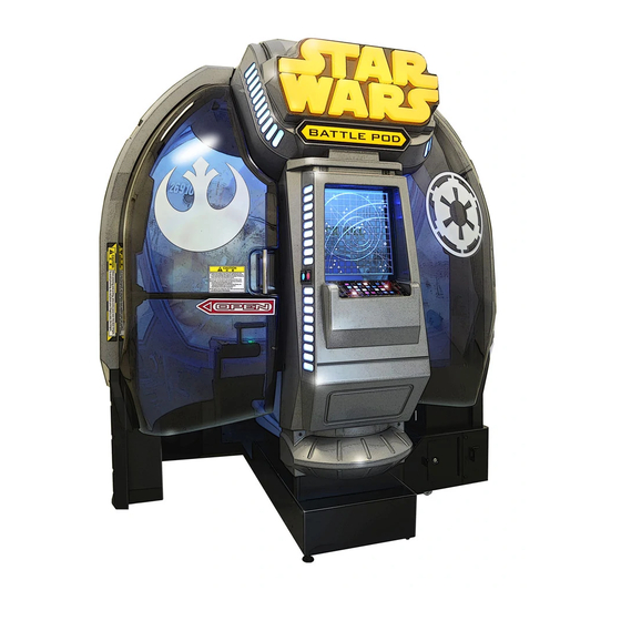
Star Wars : Battle Pod
STAR WARS © & ™ 2014 Lucasfilm Ltd. All rights reserved.
OPERATION MANUAL
取扱説明書
The actual product may differ slightly from the illustrations in this manual.
Part No.
-
First Edition Published in
June 2015
WARNING
● To ensure safe operation of the products, be sure to read this Operation Manual before use.
● Keep this OPERATION MANUAL in a safe place for easy reference when needed.
The specifications of the machine and the contents of this operation manual are
subject to change without prior notice due to product improvements.
2751001100
Advertisement
Table of Contents

Related Manuals for Bandai Namco Star Wars Battle Pod


Summary of Contents for Bandai Namco Star Wars Battle Pod
- Page 1 Star Wars : Battle Pod STAR WARS © & ™ 2014 Lucasfilm Ltd. All rights reserved. OPERATION MANUAL 取扱説明書 The actual product may differ slightly from the illustrations in this manual. Part No. First Edition Published in June 2015 WARNING ●...
- Page 2 Introduction Thank you very much for purchasing the Star Wars: Battle Pod (referred to as "this machine" in this Operation Manual). This Operation Manual describes: • How to properly understand this machine. • How to safely install, move, transport, operate, service and dispose of the machine. •...
-
Page 3: Safety Precautions
1. Safety Precautions – Be sure to read to ensure safe operation – Instructions to the Owner If you delegate the work for installing, moving, transporting, operating, maintaining or disposing of this machine to other people, ensure that these people read the relevant sections of this operation manual carefully before starting work, and observe the corresponding precautions. -
Page 4: Critical Safety Precautions
1. Safety Precautions – Be sure to read to ensure safe operation – 1-3 Critical Safety Precautions WARNING ● Should any abnormalities occur, turn off the power switch immediately to stop operations. Then, be sure to disconnect the power cord plug from the outlet. Operating the machine while the abnormality persists may result in fire or accident. - Page 5 1. Safety Precautions – Be sure to read to ensure safe operation – WARNING ● Use the consumables and service parts (including screws) that are specified by BANDAI NAMCO Games Inc. To request repairs or to order parts, contact your distributor.
-
Page 6: Machine Warning Labels
1. Safety Precautions – Be sure to read to ensure safe operation – 1-4 Machine Warning Labels WARNING ● The warning labels attached to the machine contain important information for ensuring safety. Be sure to observe the following. • In order to ensure that the warning labels attached to the machine are always clearly visible, install the machine in an appropriate, sufficiently lit location and keep the labels clean at all times. - Page 7 1. Safety Precautions – Be sure to read to ensure safe operation – ・ Warning sticker High temperature(A)NEL Part No.: ・ Warning sticker Coin mech Part No.: 461-822...
-
Page 8: Specifications
2. Specifications (1) Rated power supply 110 VAC 110 V ± 10 VAC 120 VAC 120 V ± 10 VAC 220 VAC 220 V ± 10 VAC 230 VAC 230 V ± 10 VAC (2) Rated power consumption 270 W (110 VAC / 120 VAC) 154 W (220 VAC / 230 VAC) (3) Maximum current consumption 3.0 A (110 VAC / 120 VAC) 1.6 A (220 VAC / 230 VAC) - Page 9 2. Specifications [2] When disassembled ∙Cabinet assembly Width (W) 1,210 x Depth (D) 720 x Height (H) 1,780 [mm] 1210 ∙ Seat assembly Width (W) 560 x Depth (D) 840 x Height (H) 1,270 [mm]...
- Page 10 2. Specifications ∙ Sign box assembly Width (W) 990 x Depth (D) 265 x Height (H) 545 [mm] (6) Weight [1] When installed 210 kg [2] When disassembled ∙ Cabinet assembly 170 kg ∙ Seat assembly 32 kg ∙ Sign box assembly 8 kg...
-
Page 11: Operation
7. Operation WARNING ● Should any abnormalities occur, turn off the power switch immediately to stop operations. Then, be sure to disconnect the power cord plug from the outlet. Operating the machine while the abnormality persists may result in fire or accident. ●... -
Page 12: Pre-Operation Inspection
7. Operation 7-2 Consideration for Players ● If players start feeling ill due to game images or light stimulation, they must stop playing and take a break immediately. ● In rare cases, stimulation by lights or video images may cause the player to have a seizure or lose consciousness. -
Page 13: Function Inspection (After Power On)
7. Operation 7-3-2 Safety Inspection (After Power On) Inspect the following points after turning on the power switch. If you discover an abnormality, turn off the power switch immediately to stop operations. Then, disconnect the power cord plug from the outlet and contact your distributor. (1) Is any part of the power cord or plug abnormally hot? (2) Does touching the machine give a tingling electric shock? (3) Is there a burning smell, abnormal noise or vibration? -
Page 14: Playing The Game
7. Operation 7-4 Playing the Game 7-4-1 Outline of the Game This machine enables players to take part in sensory dogfight shooting games. Players ride well-known vehicles from the Star Wars movies such as X-wing Fighters and Speeder Bikes to shoot down enemy vehicles quickly in order to carry out their missions. - Page 15 7. Operation 7-4-3 Game Flow How to Start the Game When a credit is established after a coin has been inserted, the game starts. The game mode selection screen is displayed. Selecting a Game Mode To play a one-person game, select " シングルプレイ " (SINGLE PLAY). To play a two-person game, select "...
- Page 16 7. Operation 7-5 Power Switch and Adjustment Switch 7-5-1 Turning the Power Switch On Turn on the main power switch located at the rear bottom of the cabinet assembly. Main power switch...
-
Page 17: Adjustment Switches
7. Operation 7-5-2 Adjustment Switches The adjustment switches are located inside the service door. (a) Service switch (red) サービスSW サービスSW SERVICE SW SERVICE SW (c) Select switch (b) Test switch (d) Enter switch (green) Service door Service door (a) Service switch (red) Press this button to increase the credit count without operating the coin counter. -
Page 18: Test Mode
7. Operation 7-6 Test Mode 7-6-1 Description of the Main Menu Screen (MENU) Use the service key to unlock and open the service door, and set the Test switch to ON. The MENU screen appears. Flip the Select switch up or down to select the item. The selected item blinks. -
Page 19: Game Cost Settings (Coin Options)
7. Operation 7-6-2 Game Cost Settings (COIN OPTIONS) This screen is used to change the settings of the game cost and free play. In the MENU screen, select COIN OPTIONS and press the Enter switch. The COIN OPTIONS screen appears. Flip the Select switch up or down to select the item. -
Page 20: Game Contents Settings (Game Options)
7. Operation 7-6-3 Game Contents Settings (GAME OPTIONS) This screen is used to set the game difficulty and initialize ranking. In the MENU screen, select GAME OPTIONS and press the Enter switch. The GAME OPTIONS screen appears. Flip the Select switch up or down to select the item. The selected item blinks. - Page 21 7. Operation Item Description Default Displays the cabinet-to-cabinet communication status. CHECKING: Indicates that the system is currently checking the communication status. SINGLE: Single setting OK: Enables in-store play settings and cabinet-to-cabinet communications. LINK NG: Disables in-store play settings and cabinet-to-cabinet communications DUPLICATE SEAT ID x: The same SEAT ID x is being used by multiple cabinets that are in the process of...
-
Page 22: Firmware Version
7. Operation 7-6-4 Input/Output Test (I/O TEST) Initializes the controls (levers) and perform I/O test for each switch. In the MENU screen, select I/O TEST and press the Enter switch. The I/O TEST screen appears. Flip the Select switch up or down to select the item to be displayed. Press the Enter switch to enter the selected item. - Page 23 7. Operation (a) I/F CALIBRATION Calibrate the control lever assembly and the throttle lever assembly. ● When the control lever assembly, the throttle lever assembly, the game PC board, or the NA-JV (S) PC board is replaced, or the backup data is initialized, be sure to perform calibration.
-
Page 24: (B) Switch Test
7. Operation (b) SWITCH TEST This screen is used to test each switch and control. In the I/O TEST screen, select SWITCH TEST and press the Enter switch. The SWITCH TEST screen appears. Entering each switch changes the display. Hold the Select switch flipped up and press the Enter switch to return to the I/O TEST screen. -
Page 25: Control Lever
7. Operation Item Description Tilt the control lever from side to side to increase or decrease the numerical value on the X side, and forward or backward to increase or decrease the numerical value on the Y side. If you move the lever all the way to the left side and LEFT OK! is displayed, all the CONTROL LEVER way to the right side and RIGHT OK! is displayed, all the way to the near side and UP OK! is displayed, and all the way to the far side and DOWN OK! is displayed, it... - Page 26 7. Operation (c) OUTPUT TEST This screen is used to check the fan, control lever vibration, and the LED module. This test is used to check operation. It has no effect on game play or Attract mode operation. In the I/O TEST screen, select OUTPUT TEST and press the Enter switch. The OUTPUT TEST screen appears.
-
Page 27: Link Status
7. Operation (d) LINK TEST This screen is displayed only when the "SEAT ID" of the cabinet is set to "1(MULTI / MAIN)" or "2(MULTI / SUB)" on the "7-6-3 Game Contents Settings(GAME OPTIONS)" screen shown on P-18 of this manual. In the I/O TEST screen, select LINK TEST and press the Enter switch. -
Page 28: Monitor Test Screen
7. Operation 7-6-5 Screen Adjustment (MONITOR TEST) Displays the screen for adjusting the monitor. In the MENU screen, select MONITOR TEST and press the Enter switch. The MONITOR TEST screen appears. Flip the Select switch up or down to select the item. The selected item blinks. Press the Enter switch to enter the test pattern to display. -
Page 29: Separate Check
7. Operation 7-6-6 Sound Adjustment (SOUND TEST) WARNING ● Set the cabinet volume within a range that allows the player to hear alarms and warning announcements within the operating facility. Displays the screen for sound adjustment. In the MENU screen, select SOUND TEST and press the Enter switch. The SOUND TEST screen appears. - Page 30 7. Operation Item Description Default SEPARATE CHECK Test sound is played in the following in turns at the volume for the game set in "(a) (GAMEVOLUME) BOTTOM VOLUME". BOTTOM : speaker below the seat surface MASSAGE Displays the speaker being used and its volume. GAME FRONT : Activates emission of sound from the front speaker at the volume set for game mode.
- Page 31 7. Operation 7-6-7 Displaying/Initializing Game Data (BOOKKEEPING) Displays or initializes various data related to the game. In the MENU screen, select BOOKKEEPING and press the Enter switch. The BOOKKEEPING screen appears. Flip the Select switch up or down to select the item. The selected item blinks. Press the Enter switch to enter the selected item.
-
Page 32: Error Log Screen
7. Operation 7-6-8 ERROR LOG Checks the history of detected error logs. In the MENU screen, select BOOKKEEPING and press the Enter switch. The ERROR LOG screen appears. Flip the Select switch up or down to select NEXT, then press the Enter switch to move to the next page. -
Page 33: Other Options (Others)
7. Operation 7-6-9 Other Options (OTHERS) Displays, sets or initializes the current time and the software version. In the MENU screen, select OTHERS and press the Enter switch. The OTHERS screen appears. Flip the Select switch up or down to select the item. The selected item blinks. Press the Enter switch to enter the selected item. - Page 34 7. Operation (a) Setting Maintenance Time (MAINTENANCE TIME SETTING) Sets the maintenance time. (See P-34 "7-8 About Maintenance Time".) If you change the setting, the machine will automatically restart after you set the Test switch to OFF. In the OTHERS screen, select MAINTENANCE TIME SETTING and press the Enter switch. The MAINTENANCE TIME SETTING screen appears.
- Page 35 7. Operation (b) Setting the Clock (CLOCK SETTING) Sets the time of the built-in clock. In the OTHERS screen, select CLOCK SETTING and press the Enter switch. The CLOCK SETTING screen appears. Flip the Select switch up or down to select the item. The selected item blinks. Press the Enter switch to enter the selected item.
- Page 36 7. Operation 7-7 About Maintenance Time This machine is equipped with a function that clears the system by rebooting regularly ("Maintenance time") to reduce the load on the game PC board caused by prolonged continuous operation. Before shipping, the maintenance time is set at 7:00 AM. However, this can be changed by following the description in P-32 "(a) Setting Maintenance Time (MAINTENANCE TIME SETTING)".
- Page 37 7. Operation 7-8 Cleaning ● Do not use thinner, benzene, gasoline or other organic solvents. Doing so may degrade the materials. (1) Cleaning the Monitor Glass Wipe away any dirt or dust on the screen surface using a soft cloth moistened with a small amount of water, then wipe dry using a dry soft cloth.
-
Page 38: Assembly Preparation
8. Technician's Manual – Must be performed by a technician – 8A. Installation and Assembly 8A-1 Assembly Preparation 8A-1-1 Number of Workers and Work Time The following numbers of workers and work times are required for assembly work. Number of workers Delivery work: See "6-2 Transportation".) Assembly work: Two or more technicians Work time... - Page 39 8A. Service – Must be performed by a technician – 8A-2 Assembly 8A-2-1 Installing the Seat Assembly Remove the seat service door. Remove the seat service door. Torx bolt (M5 x 12) (Remove the four bolts.) Torx bolt (M5 x 12) (Loosen the three bolts.)
-
Page 40: Install The Seat Assembly
8A. Service – Must be performed by a technician – Install the seat assembly. Install the seat assembly using the four flange socket bolts (M8 x 16). Connect the connector. Torx bolt (M5 x 12) (Attach the four bolts.) Install the seat service door. Torx bolt (M5 x 12) (Tighten the three bolts.) - Page 41 8A. Service – Must be performed by a technician – 8A-2-2 Installing the Sign Box Assembly Remove the service door. (See "8B-4-1 Removing and Installing the Service Door".) Install the sign box. Insert the sign box into the top part of the cabinet assembly. Phillips hexagon head bolt (with flat and spring washers) (M6 x 16)
- Page 42 8A. Service – Must be performed by a technician – Install the connector and connector cover. Torx bolt (M5 x 12) (Use one bolt to fix.) Install the connector cover. Connect the connector.
- Page 43 8A. Service – Must be performed by a technician – 8A-2-3 Inserting the USB Dongle WARNING ● In order to avoid electric shock, accident or injury to yourself or others as well as damage to the electronic circuits, be sure to turn off the main power switch before starting this task. Remove the service door.
- Page 44 8A. Service – Must be performed by a technician – 8A-2-4 Level Adjuster Adjustment Lower the level adjuster until the casters are at a height of approximately 5 mm from the floor. Caster Approximately 5 mm Level adjuster...
- Page 45 8A. Service – Must be performed by a technician – 8A-3 Connecting the Power Cord and Ground Wire and the LAN Cable WARNING ● Be sure to install the ground wire. Failure to connect the ground wire may result in electric shock in the event of a short-circuit.
- Page 46 8A. Service – Must be performed by a technician – 8A-3-2 Connecting the LAN Cable Connect the LAN cable. WARNING ● In order to avoid electric shock, accident or injury to yourself or others as well as damage to the electronic circuits, be sure to turn off the main power switch of the game cabinet before starting this task.
-
Page 47: Cabinet Assembly
8A. Service – Must be performed by a technician – WARNING ● In order to avoid electric shock, accident or injury to yourself or others as well as damage to the electronic circuits, be sure to turn off the main power switch of the game cabinet before starting this task. - Page 48 8A. Service – Must be performed by a technician – Secure the LAN cable using the reuse clamp. Secure the LAN cable using the reuse clamp. LAN cable Reuse clamp Insert to the back. ● Check the shape and orientation of the connector before inserting the LAN cable. ●...
-
Page 49: Turning The Power Switch On
8A. Service – Must be performed by a technician – 8A-4 Turning the Power Switch On Turn on the main power switch at the rear bottom of the cabinet assembly. Main power switch... - Page 50 11. Wiring Diagram (1/2) 11-1 Overall Connection Diagram (U.S. model, 120 VAC) =ALL.AA9310 CABINET(BNAA)ASSY =ALL.AA9310.AA9311 =ALL.AA9310.AA9314 =ALL.AA9330 UNDER CABINET ASSY MONITOR CABINET ASSY SIGNBOX ASSY =ALL.AA9310.AA9368 -X274 COIN(BNAA) ASSY SM 2P-P SM 2P-R -X265 AWG 22 LED Bar Module 12VDC Mini UMNL 9P-C -LED1 AWG 22...
- Page 51 11. Wiring Diagram (2/2) =ALL.AA9310 CABINET(BNAA)ASSY =ALL.AA9310.AA9314 =ALL.AA9402 AWG 26 MONITOR CABINET ASSY (WH) GAME SOFT(EXP)ASSY -FM1.FM1 AWG 26 -CB20.CN2 (BK) DC Axial Fan Motor RCA Plug RCA Jack RCA(L) (WH) USB 3 JV I/O -CB18.CN1 AWG 26 0.18A 24VDC -X308 -X268 USB A Male CN1...
- Page 52 11. Wiring Diagram (1/2) 11-2 Overall Connection Diagram (European model, 230 VAC) =ALL.AA9304 CABINET(BNAE)ASSY =ALL.AA9304.AA9311 =ALL.AA9304.AA9314 =ALL.AA9330 UNDER CABINET ASSY MONITOR CABINET ASSY SIGNBOX ASSY =ALL.AA9304.AA9364 -X274 COIN(BNAE) ASSY SM 2P-P SM 2P-R AWG 22 LED Bar Module 12VDC Coin Door -LED1 AWG 22 -X309...
- Page 53 11. Wiring Diagram (2/2) =ALL.AA9304 CABINET(BNAE)ASSY =ALL.AA9304.AA9314 =ALL.AA9402 AWG 26 MONITOR CABINET ASSY (WH) GAME SOFT(EXP)ASSY -FM1.FM1 AWG 26 -CB20.CN2 (BK) DC Axial Fan Motor RCA Plug RCA Jack RCA(L) (WH) USB 3 JV I/O -CB18.CN1 AWG 26 0.18A 24VDC -X308 -X268 USB A Male CN1...
- Page 54 11. Wiring Diagram (1/2) 11-3 Overall Connection Diagram (Asian model, 110 to 120 VAC, 220 to 240 VAC) =ALL.AA9302 CABINET(ASIA)ASSY =ALL.AA9302.AA9311 =ALL.AA9302.AA9314 =ALL.AA9330 UNDER CABINET ASSY MONITOR CABINET ASSY SIGNBOX ASSY =ALL.AA9302.AA9368 -X274 COIN(BNAA) ASSY SM 2P-P SM 2P-R -X265 AWG 22 LED Bar Module 12VDC...
- Page 55 11. Wiring Diagram (2/2) =ALL.AA9302 CABINET(ASIA)ASSY =ALL.AA9302.AA9314 =ALL.AA9402 AWG 26 MONITOR CABINET ASSY GAME SOFT(EXP)ASSY -FM1.FM1 AWG 26 -CB20.CN2  DC Axial Fan Motor RCA Plug RCA Jack RCA(L) USB 3 JV I/O -CB18.CN1 AWG 26 0.18A 24VDC -X308 -X268 USB A Male CN1...
Need help?
Do you have a question about the Star Wars Battle Pod and is the answer not in the manual?
Questions and answers