Table of Contents
Advertisement
SERVICE MANUAL
Dolby noise reduction manufactured under license from
Dolby Laboratories Licensing Corporation.
"DOLBY" and the double-D symbol a are trademarks of
Dolby Laboratories Licensing Corporation.
MICROFILM
TXD-RE210
Model Name Using Similar Machanism
CD
CD Machanism Type
Section
Base Unit Name
Optical Pick-up Type
Tape deck Model Name Using Similar Machanism
Section
Tape Transport Mechanism Type
SPECIFICATIONS
COMPACT DISC CASSETTE DECK
AEP Model
NEW
CDM28-5BD23
BU-5BD23
KSS-213B/S-N
TXD-R11
TCM-190RB52C
Advertisement
Table of Contents

Related Manuals for Sony TXD-RE210


Summary of Contents for Sony TXD-RE210
- Page 1 TXD-RE210 SERVICE MANUAL AEP Model Dolby noise reduction manufactured under license from Model Name Using Similar Machanism Dolby Laboratories Licensing Corporation. CD Machanism Type CDM28-5BD23 “DOLBY” and the double-D symbol a are trademarks of Dolby Laboratories Licensing Corporation. Section Base Unit Name...
-
Page 2: Table Of Contents
7-4. Mechanism Section -2 ..........33 PARTS LIST ARE CRITICAL TO SAFE OPERATION. 7-5. CD Mechanism Section -1 ........34 REPLACE THESE COMPONENTS WITH SONY PARTS WHOSE PART NUMBERS APPEAR AS SHOWN IN THIS MANUAL OR IN 7-6. CD Mechanism Section -2 ........35 SUPPLEMENTS PUBLISHED BY SONY. -
Page 3: Servicing Note
SECTION 1 SERVICING NOTE NOTES ON HANDLING THE OPTICAL PICK-UP NOTES ON LASER DIODE EMISSION CHECK BLOCK OR BASE UNIT The laser beam on this model is concentrated so as to be focused on the disc reflective surface by the objective lens in the optical pick- The laser diode in the optical pick-up block may suffer electrostatic up block. -
Page 4: General
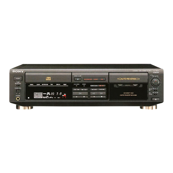
SECTION 2 This section is extracted from GENERAL instruction manual. LOCATION AND FUNCTION OF CONTROLS 5 6 7 8 !º !¡ @£ @™ @¡ @º !ª !• !¶ !§ !∞ !¢ !£ !™ 1 POWER switch !∞ CD operating buttons 2 Disc tray ) ±... -
Page 5: Disassembly
SECTION 3 DISASSEMBLY Note : Follow the disassembly procedure in the numerical order given. 3-1. FRONT PANEL REMOVAL Disc table Loading panel Chassis 5 Screw (+BV TP 3 x 6) 6 Wire (Flat type) (7 core) to Main board (CN806) 7 Wire (Flat type) (23 core) to Main board (CN805) 8 Wire (Flat type) (7 core) to Main board (CN801) 9 Wire (Flat type) (9 core) to Main board (CN804) -
Page 6: Mechanism Deck Removal
3-3. MECHANISM DECK REMOVAL 3 Two Screws (+BV TP 2.6 x 8) Casstte lid assy Front panel assy Mechanism deck 1 Press § button 3 Two Screws (+BV TP 2.6 x 8) – 6 –... -
Page 7: Adjustments
SECTION 4 ADJUSTMENTS 4-1. MECHANICAL ADJUSTMENTS Test tape Tape Contents PRECAUTION 1. Clean the following parts with a denatured-alcohol-moistened P-4-A100 10 kHz, –10dB Azimuth Adjustment swab : P-4-L300 315Hz, PB Level Adjustment record/playback head pinch roller WS-48B 3kHz, Tape Speed Adjustment erase head rubber belts capstan... - Page 8 3. Playback Mode Sample Value of Wow and flutter W. RMS (JIS) within 0.3% test tape (test tape : WS-48B) P-4A100 (10kHz, –10dB) Osilloscope Playback Level Adjustment 47 k Ω L-CH Procedure : Mode : Playback test tape P-4-L300 level meter (315Hz, 0dB) 47 k Ω...
- Page 9 Record Level Adjustment CD SECTION Procedure : Note : 1. Mode : Record 1. CD Block basically constructed to operate without adjustment. Therefore, check each item in order given. AF OSC 2. Use YEDS-18 disc (3-702-101-01) unless otherwise indicated. 315Hz 72.3mV (–20.6dB) blank tape 3.
- Page 10 RF PLL Free-run Frequency Check E-F Balance (1 Track Jump) Check Procedure : oscilloscope 1. Connect frequency counter to test point (PLCK) with lead wire. (DC range) frequency counter BD board BD board TP (TE) TP (PLCK) TP (VC) – –...
-
Page 11: Explanation Of Ic Terminals
SECTION 5 EXPLANATION OF IC TERMINALS IC801 µPD78044FGF029-3B9 (SYSTEM CONTROL) Pin No. Pin name Description AUTO REC LEVEL LED ON/OFF. 2–7 1G – 6G FL grid drive. – Power supply (+5V) Command clock output for IC101 and IC104. DATA Command data output for IC101 and IC104. SENS SENS input for IC101 and IC104. - Page 12 Pin No. Pin name Description LD ON Laser diode ON output. – Power supply (+5V). HP SEL Headphone output selection. INPUT SEL Recording source select. –––––––––––––––––––––––––––––––– TC LINE MUTE TC line mute control output. 56–70 S1–S15 FL segment output. VDISP –...
-
Page 13: Diagrams
SECTION 6 DIAGRAMS CIRCUIT BOARDS LOCATION TRANSFORMER board BD board POWER SW board LEAF SW board HP board LOADING board PANEL board MAIN board AUDIO board VOL board – 13 –... -
Page 18: Exploded Views
SECTION 7 EXPLODED VIEWS NOTE : -XX, -X mean standardized parts, so they may The mechanical parts with no reference number The components identified by mark ! have some difference from the original one. in the exploded views are not supplied. or dotted line with mark ! are critical Items marked “... -
Page 19: Panel Section
3-354-957-01 JOINT (LOCK LEVER) X-3373-251-1 PANEL ASSY, FRONT 3-354-962-01 SPRING (EJ SAFTY SPRING R) 3-931-429-01 BUTTON (POWER) 3-354-956-07 LEVER (EJ SAFTY LEVER R) 3-008-600-11 EMBLEM (5-AR), SONY 4-959-232-11 SPRING (R), TORSION 4-951-620-01 SCREW (2.6X8), +BVTP 3-354-963-01 DAMPER 3-931-378-01 KNOB (F10) -
Page 20: Mechanism Section-1
7-3. MECHANISM SECTION-1 TCM-190RB52C HRPE101 (including r A,B) Ref. No. Part No. Description Remark Ref. No. Part No. Description Remark ––––––– ––––––– –––––––––– ––––––– ––––––– ––––––– –––––––––– –––––– X-3366-047-1 LEVER (PINCH F) ASSY X-3367-630-1 FLYWHEEL (REV) ASSY 3-356-713-01 WASHER 3-359-417-01 BELT (FLAT), CAPSTAN 3-907-362-01 SPRING, TORSION X-3366-970-1 TABLE ASSY, REEL X-3367-629-1 FLYWHEEL (FWD) ASSY... -
Page 21: Mechanism Section-2
7-4. MECHANISM SECTION-2 TCM-190RB52C Ref. No. Part No. Description Remark Ref. No. Part No. Description Remark ––––––– ––––––– –––––––––– ––––––– ––––––– ––––––– –––––––––– –––––– X-3363-790-1 CHASSIS ASSY MECHANICAL 3-359-429-11 SLIDER (BRAKE PLATE) 3-359-469-01 SPACER 3-359-420-01 GEAR (CAM GEAR) 3-359-425-01 SLIDER (REVERSE SLIDER) 3-359-456-01 SPRING(TRIGGER SPRING),TORSION 3-359-426-01 LEVER (REVERSE LEVER) X-3366-569-1 ARM ASSY, FR... -
Page 22: Cd Mechanism Section-1
7-5. CD MECHANISM SECTION-1 CDM28-5BD23 (including ¢ A) M903 BU-5BD23 ¢ A Ref. No. Part No. Description Remark Ref. No. Part No. Description Remark ––––––– ––––––– –––––––––– ––––––– ––––––– ––––––– –––––––––– –––––– 4-960-836-01 TABLE, DISC 4-917-583-21 BRACKET, YOKE 4-960-835-01 HOLDER (M) 4-933-134-01 SCREW (+PTPWH M2.6X6) 1-452-719-11 MAGNET ASSY 4-959-996-01 SPRING (932), COMPRESSION... -
Page 23: Cd Mechanism Section-2
7-6. CD MECHANISM SECTION-2 BU-5BD23 M101 M102 The components identified by mark ! or dotted line with mark ! are critical for safety. Replace only with part number specified. Ref. No. Part No. Description Remark Ref. No. Part No. Description Remark –––––––... -
Page 24: Electrical Parts List
SECTION 8 AUDIO ELECTRICAL PARTS LIST NOTE : SEMICONDUCTORS Due to standardization, replacements in the In each case, u : µ , for example : The components identified by mark ! parts list may be different from the parts speci- uA.. - Page 25 AUDIO Ref. No. Part No. Description Remark Ref. No. Part No. Description Remark ––––––– ––––––– –––––––––– ––––––– ––––––– ––––––– –––––––––– –––––– 1-216-091-00 METAL CHIP 1/10W C184 1-135-156-21 TANTALUM CHIP 6.8uF 1-216-091-00 METAL CHIP 1/10W C185 1-135-155-21 TANTALUM CHIP 4.7uF 1-216-073-00 METAL CHIP 1/10W C186 1-163-038-91 CERAMIC CHIP...
- Page 26 LOADING MAIN TRANSFORMER LEAF SW Ref. No. Part No. Description Remark Ref. No. Part No. Description Remark ––––––– ––––––– –––––––––– ––––––– ––––––– ––––––– –––––––––– –––––– R127 1-216-049-91 METAL GLAZE 1/10W 1-650-836-11 LOADING BOARD R131 1-216-037-00 METAL CHIP 1/10W ************** R132 1-216-049-91 METAL GLAZE 1/10W R141...
- Page 27 MAIN TRANSFORMER Ref. No. Part No. Description Remark Ref. No. Part No. Description Remark ––––––– ––––––– –––––––––– ––––––– ––––––– ––––––– –––––––––– –––––– C501 1-126-964-11 ELECT 10uF * CNP504 1-691-916-11 CONNECTOR, BOARD TO BOARD C502 1-126-923-11 ELECT 220uF CNP701 1-564-524-11 PLUG, CONNECTOR 9P C503 1-104-664-11 ELECT 47uF...
- Page 28 MAIN TRANSFORMER Ref. No. Part No. Description Remark Ref. No. Part No. Description Remark ––––––– ––––––– –––––––––– ––––––– ––––––– ––––––– –––––––––– –––––– IC801 8-759-453-42 IC uPD78044FGF-029-3B9 R103 1-247-843-11 CARBON 3.3K 1/4W IC802 8-759-165-82 IC PST600E-T R104 1-249-424-11 CARBON 3.9K 1/4W IC803 8-759-000-48 IC MC14052BCP IC805...
- Page 29 MAIN TRANSFORMER Ref. No. Part No. Description Remark Ref. No. Part No. Description Remark ––––––– ––––––– –––––––––– ––––––– ––––––– ––––––– –––––––––– –––––– R266 1-247-807-31 CARBON 1/4W R708 1-249-429-11 CARBON 1/4W R271 1-247-852-11 CARBON 7.5K 1/4W R272 1-247-852-11 CARBON 7.5K 1/4W R709 1-249-419-11 CARBON 1.5K...
- Page 30 MAIN TRANSFORMER PANEL POWER SW VOL Ref. No. Part No. Description Remark Ref. No. Part No. Description Remark ––––––– ––––––– –––––––––– ––––––– ––––––– ––––––– –––––––––– –––––– < VIBRATOR > R907 1-249-422-11 CARBON 2.7K 1/4W R908 1-249-424-11 CARBON 3.9K 1/4W X801 1-577-358-21 VIBRATOR, CERAMIC (4MHz) R909 1-249-427-11 CARBON...
- Page 31 PANEL POWER SW VOL Ref. No. Part No. Description Remark ––––––– ––––––– –––––––––– ––––––– S927 1-762-567-11 SWITCH, SLIDE (DOLBY NR) S928 1-762-609-11 SWITCH, SLIDE (DIR MODE) ************************************************************ MISCELLANEOUS ************* 1-782-313-11 WIRE (FLAT TYPE) (26 CORE) ! 10 1-575-651-21 CORD, POWER 1-769-917-11 WIRE (FLAT TYPE) (9 CORE) 1-773-182-11 WIRE (FLAT TYPE) (23 CORE) 1-775-370-11 WIRE (FLAT TYPE) (7 CORE)
- Page 32 TXD-RE210 Sony Corporation 97E027546-1 Printed in Hungary © 1997.5 9-960-937-11 Home A&V Products Company Published by General Engineering Dept. (Shibaura) – 44 –...
Need help?
Do you have a question about the TXD-RE210 and is the answer not in the manual?
Questions and answers