Advertisement
Quick Links
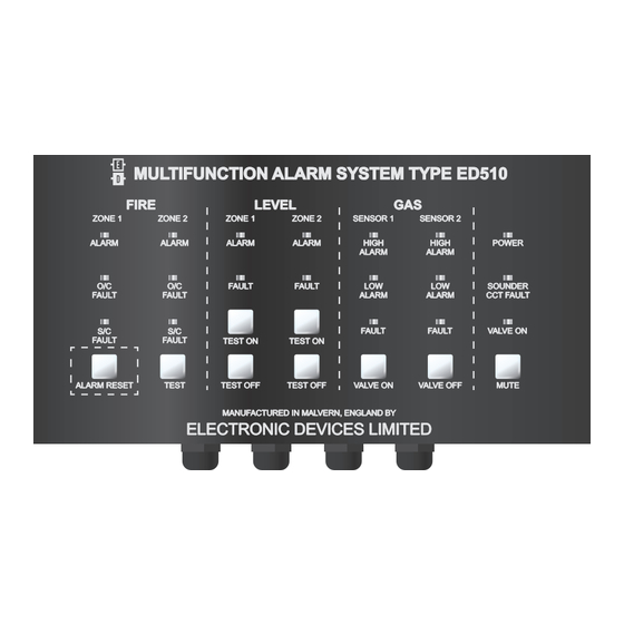
MULTIFUNCTION ALARM SYSTEM TYPE ED510
FIRE
ZONE 1
ZONE 2
ALARM
ALARM
O/C
FAULT
FAULT
S/C
FAULT
FAULT
ALARM RESET
TEST
MULTIFUNCTIONAL ALARM SYSTEM
INSTRUCTION MANUAL
Address: Enigma House, Enigma Business Park, Malvern, Worcestershire, WR14 1GD
Tel: +44 (0)1684 891500 Fax: +44 (0)1684 891600
Email: sales@electronic-devices.co.uk Website: www.electronic-devices.co.uk
LEVEL
ZONE 1
ALARM
O/C
FAULT
S/C
TEST ON
TEST OFF
MANUFACTURED IN MALVERN, ENGLAND BY
ELECTRONIC DEVICES LIMITED
ED510
GAS
ZONE 2
SENSOR 1
ALARM
HIGH
ALARM
FAULT
LOW
ALARM
FAULT
TEST ON
TEST OFF
VALVE ON
SENSOR 2
HIGH
POWER
ALARM
LOW
SOUNDER
ALARM
CCT FAULT
FAULT
VALVE ON
VALVE OFF
MUTE
Advertisement

Related Manuals for Electronic Devices Limited ED510

Summary of Contents for Electronic Devices Limited ED510
- Page 1 MULTIFUNCTION ALARM SYSTEM TYPE ED510 FIRE LEVEL ZONE 1 ZONE 2 ZONE 1 ZONE 2 SENSOR 1 SENSOR 2 ALARM ALARM ALARM ALARM HIGH HIGH POWER ALARM ALARM FAULT FAULT SOUNDER FAULT FAULT ALARM ALARM CCT FAULT FAULT FAULT VALVE ON...
-
Page 2: Table Of Contents
EDP SEMICONDUCTOR GAS SENSORS AUDIABLE AND VISUAL ALARMS CONNECTING A SOLENOID VALVE TEST PROCEEDURE & SETUP FIRE EQUIPMENT WATER LEVEL EQUIPMENT EDP CALIBRATION PROCEEDURE EDN CALIBRATION PROCEEDURE PRINTED CIRCUIT BOAD LAYOUT CUTOUT TEMPLATE ED510 - GAS DETECTOR ED510 IM REV 2 - 23.08.2017... - Page 3 THE EQUIPMENT MUST NOT BE MODIFIED IN ANY WAY AND MUST BE INSTALLED AND SERVICED BY COMPETENT PERSONNEL ONLY. IF IN DOUBT CONSULT ELECTRONIC DEVICES LTD (01684) 891500 GENERAL The ED510 is a fixed installation fire, gas and level detection system operating from a nominal 12 or 24VDC supply depending upon model. FEATURES •...
-
Page 4: User Operation
Once all conditions have been cleared and RESET the gas solenoid valve can be operated by pressing the VALVE ON button. It is important to check all pilot lights on the gas appliance and ensure they are ignited where necessary. The ED510 has a general alarm output relay which can be used for various purposes including the shutdown of air conditioning, HVAC etc.. -
Page 5: Installation
2. Fixed temperature heat detectors will signal an alarm once the temperature exceeds a pre-defined level and are effective in environments with fluctuating temperatures (such as boiler rooms) or where the ambient temperature is unusually high (for example in an engine room). ED510- GAS DETECTOR ED510 IM REV 2 - 23.08.2017... - Page 6 REMOTE REMOTE INDICATOR INDICATOR APOLLO APOLLO APOLLO ORBIS ORBIS ORBIS REMOTE REMOTE INDICATOR INDICATOR YBO-R/4M YBO-R/4M YBO-R/5M YBO-R/5M REMOTE INDICATOR NOTE ED510 - GAS DETECTOR ED510 IM REV 2 - 23.08.2017...
-
Page 7: Water Level Detection
Xenon Beacon mounted externally (as high as possible). Alerting other boat users etc. when the vessel is unmanned. WIRING TYPICAL FLOAT SWITCHES Control unit zone terminals E.O.L ED735 float switches ED510- GAS DETECTOR ED510 IM REV 2 - 23.08.2017... -
Page 8: Gas Detection
Electrochemical Cell and Catalytic gas sensors can be connected enabling detection of other toxic gases and flammable only detection. Attention is drawn to the need for calibration after the ED510 has been energized for 24 hours. When supplied alarm levels are approximately set for the target gas, if stated with the order, if not 25% and 50% LEL Butane is used. Therefore a measure of immediate protection is obtained once correct operation is assured. -
Page 9: Connecting A Solenoid Valve
Both entry and exit connections are 3/8th in BSP female and are suitable for Propane or Butane bottles at a pressure in the range of 0 - 0.01 Bar. The valve has a 6.7mm orifice. When Relay RL4 is fitted the ED510 is suitable for the connection of other solenoid valves taking a maximum current of 1A. -
Page 10: Water Level Equipment
ZONE 2 SOUNDER/BEACON GAS SENSOR CONNECTIONS LEVEL SWITCH CONNECTIONS FIRE DETECTOR CONNECTIONS CONNECTIONS POWER SUPPLY SEE PAGE 7 SEE PAGE 6 SEE PAGE 5 SEE PAGE 7 INPUT 12V / 24V ED510 - GAS DETECTOR ED510 IM REV 2 - 23.08.2017... - Page 11 RESET button on the ED510 front panel until the A1 LED goes out then turn slowly anti clockwise again until it just illuminates. 4. Repeat step 4 for the A2 high alarm calibration on the same sensor calibration with the following alterations:...
-
Page 12: Edn Calibration Proceedure
5. Whilst the EDN is giving the correct output go to the ED510 control panel and adjust the A1 low alarm potentiometer (see diagram below) until the A1 LED on front of panel just illuminates. If the A1 LED on front of ED510 is not illuminated rotate the potentiometer anti-clockwise to increase sensitivity. - Page 13 ED510- GAS DETECTOR ED510 IM REV 2 - 23.08.2017...
- Page 14 ED510 - GAS DETECTOR ED510 IM REV 2 - 23.08.2017...
Need help?
Do you have a question about the ED510 and is the answer not in the manual?
Questions and answers