Table of Contents
Advertisement
Quick Links
Advertisement
Table of Contents

Related Manuals for BolyGuard BG500L

Summary of Contents for BolyGuard BG500L
- Page 1 MMS/GPRS Security Camera User’s Manual BG500 series : For model BG500L/BG500K...
-
Page 2: Table Of Contents
Content 1 Product Feature..............2 1.1 General Description..........2 1.2 Camera Overview............. 2 1.3 Shooting Information Display......3 1.4 Product Feature............5 2 Cautions ................6 3 Quick Start................ 7 3.1 TF card and SIM card..........7 3.2 Battery and power adapter ........7 3.3 Quick start.............. -
Page 3: Product Feature
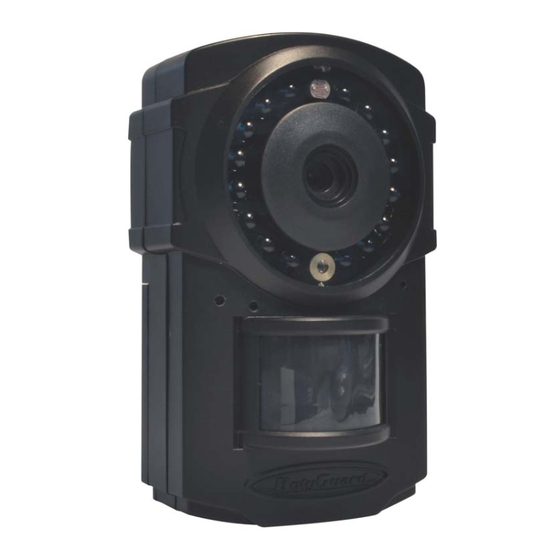
BG500 series Product Feature Product Feature 1.1General Description The BG500 series security camera is a mini MMS/GPRS alarm system, based on MMS (Multimedia Messaging Service), GSM SMS (Short Message Service) and GSM voice technologies. When it is activated, it will send MMS (pictures) alerts to your mobile phone or e-mail address immediately once the monitored region is abnormal. -
Page 4: Shooting Information Display
BG500 series Product Feature 1.3 Shooting Information Display When the camera is turned on (the power switch is slid to ON position), the camera setting information will be displayed in the monitor. - Page 5 BG500 series Product Feature *The function in ( ) can work only in Setup status; *The function in [ ] can work only in Arm status.
-
Page 6: Product Feature
BG500 series Product Feature 1.4 Product Feature 1. This camera can take 5megapixel photos and VGA videos. 2. It uses TF card (Micro-SD card) to store images and videos. 3. It can send MMS images to the mobile phone or to an e-mail address. -
Page 7: Cautions
BG500 series 2 Cautions 2 Cautions Please use this product according to the law. Respect one another’s privacy. Do not monitor other people’s home or privacy. We hold no responsibility for the illegal use of this product. We don’t guarantee for the document veracity, reliability or any content except regulated in proper laws. -
Page 8: Quick Start
BG500 series 3 Quick Introductions 3 Quick Start 3.1 TF card and SIM card Open the battery cover. Insert TF card and SIM card into the card slot in accordance with the direction shown. Follow the right direction. Please make sure that your SIM card has opened the GPRS data business before use. -
Page 9: Quick Start
BG500 series 3 Quick Introductions 3.3 Quick start Settings must be done 1) Must set a administrator number to the security camera. 2) Must correctly set the network parameters for MMS and e-mail. 3) Must have at least one receiving phone number and one receiving e-mail address. - Page 10 BG500 series 3 Quick Introductions Step2: edit MMS parameters via computer 1) Use the USB cable to connect the camera with your computer. 2) Wait for the 10-20 seconds for the camera to acquire a signal. After the SIM card icon appears, press “MENU”...
- Page 11 BG500 series 3 Quick Introductions Different telecom providers have different parameters. Please contact your network service provider for the detail telecom parameters. Step 3: send MMS manually After you finish the MMS settings in the computer, please restart your camera. After the camera acquiring the signal and the SIM card icon appears, target an object and press “►”...
- Page 12 BG500 series 3 Quick Introductions previous or next photo. Then press “MENU” and you can see a send Phone [MMS] interface, press “OK” to send out the MMS. After a few seconds, you will receive a MMS in your phone. Step4: go to Arm Status Arm status is the normal work status.
-
Page 13: Advanced Operations
BG500 series 4 Advanced Operations 4 Advanced Operations 4.1 Mount the camera Camera can be mounted on a wall or put down on any suitable horizontal surface. 1) In accordance with a base board installing hole, make holes on the wall with a power drill. 2) Fix base board with the host by connecting screw hole. -
Page 14: Change Camera Settings Via Control Panel
BG500 series 4 Advanced Operations 4.3 Change camera settings via control panel To view the camera settings menu, press MENU in the Setup status. The setup menu will be shown on the LCD. Submenu Description Camera There are two camera modes: Camera or Mode Video. - Page 15 BG500 series 4 Advanced Operations images or videos at a preset time intervals regardless of whether motions are detected. The default parameter is Off which means the timer function is disabled. Changing this parameter to a non-zero value turns on the Time Lapse mode, and camera will take photos at given time interval.
- Page 16 BG500 series 4 Advanced Operations disabled after each triggering in ON mode. During this time the PIR of the device will not react to the motion of human (or animal). The minimum interval is 0 second. It means the PIR works all the time.
-
Page 17: Use The Remote Control
BG500 series 4 Advanced Operations studied with this camera first. Please see 4.5 to find the method to connect or remove a wireless sensor. If you choose “Format SD”, the system will delete all images or videos stored in the SD card. Format SD So make sure that you have made a backup of important data. -
Page 18: Load Or Remove A Wireless Sensor
BG500 series 4 Advanced Operations Setup status Study Code Menu Study Code Menu Method to add remote control(s) to the camera: Enter the Setup status, press Menu and enter the Study Code submenu. Choose “RCH”, press OK button, then press button A of the remote control. When it's successful, there will be a "*”before RCH. -
Page 19: Change The Settings Via Sms
BG500 series 4 Advanced Operations Setup status Study Code Menu Study Code Menu 3. When you want to remove the wireless sensor. Please enter the study code menu, press LEFT button to cancel the “*”. If there is not a “*” before the zone, it means the sensor has been removed from the camera. -
Page 20: Set Administrator Number
BG500 series 4 Advanced Operations user Check camera status administrator, normal user Get help information administrator, normal user 4.6.2 Set administrator number You should set a administrator number to receive MMS or control your camera when you first use this camera. -
Page 21: Set Mms Parameters
BG500 series 4 Advanced Operations 10.0.0.172, 80, cmwap,,, administrator number, PhoneNum2, PhoneNum3, PhoneNum4 Method 2: editing the BG500.TXT: PhoneNum2=xxx,PhoneNum3=xxx,PhoneNu m4=xxx 4.6.4 Set MMS parameters If you want to get instant MMS images when the camera is triggered, you should set the MMS parameters correctly. -
Page 22: Set Receive Phone Number
BG500 series 4 Advanced Operations 4.6.5 Set email parameters You also can choose Send Email mode to get the pictures via a cheaper channel. This Send Email mode can send out the pictures via GPRS internet ,not WAP, so the communication cost is much lower than MMS. -
Page 23: Get On Spot Photo
BG500 series 4 Advanced Operations The first receive phone number is the administrator number. Reply SMS: http://mmsc.monternet.com, 10.0.0.172, 80, cmwap, , ,administrator number, receive phone number 1, receive phone number 2, receive phone number 3, Method2: editing the BG500.TXT: fill the receive phone number field. -
Page 24: Disarm
BG500 series 4 Advanced Operations If successful, reply SMS: Arm mode is active! If failed, reply SMS: Command error! Please check again. Method2: use the remote control Use the remote control, press the button “A” to arm the camera; 4.6.9 Disarm Method1: send SMS command: Edit SMS #D# and send to your camera’s SIM card. -
Page 25: Set Camera Parameters
BG500 series 4 Advanced Operations port, protocol,Number1,Number2,Number3, Number4, Alarm: on /off, Interval 0m:0s,photo Burst 1, Send Mode: Local/Number/Email, Work Day 1111111, Timer: off/on 09h00m:17h00m, Date Time:2011/7/12 18:12:12,Active Zone:0111111 4.6.11 Set camera parameters You can send SMS commands as the table shows. #e#b1# B: Photo burst 1: the numbers of continuously taken... -
Page 26: Format Tf Card
BG500 series 4 Advanced Operations 10: the range is from 5s to 60s. 11 #e#d111001 D: Work day: 1 means ON, 0 means OFF. From Sunday to Saturday. If successful,reply SMS: Arm: On, Photo, 5M, Pir-Trig: Normal, Interval:0s, AV-Len:10s, Lapse: Off, Burst:1, Mode: Phone, W-Day:1110001, W-hour: Off, 2013/01/22 16:41. -
Page 27: Get Help
BG500 series 4 Advanced Operations camera’s SIM card. If successful , it will reply SMS: The password is successfully changed to 4321. 4.6.14 Get help Method: send SMS command: Edit SMS #H# and send to your camera’s SIM card. If successful,it will reply SMS: A:Arm, D:Disarm, E:Edit (B: Burst, C: Camera Mode, D: Work Day, H: Work Hour, I: Interval, L: Lapse, M: Send Mode, P: PIR Trigger, S: Photo Size, V: Video Length,... - Page 28 BG500 series 4 Advanced Operations phone address 678903# Receiving #R#Email1@163.com#Email2@163.com Email Address #Email3@163.com# spot Photo Disarm 10 Check camera settings 11 Set Camera #E #B1#Mp#d1110001#hOFF#t# Parameters (B:Burst,C:Camera Mode,D:Work Day,H:Work Hour,I:Interval,L:Lapse,M:Send Mode,P:Pir Trigger,S:Photo Size, V:Video Length,T:Time Set) 12 Format Card 13 Set Password #P#5555# 14 Help A:Arm,D:Disarm,E:Edit(B:Burst,C:Came...
-
Page 29: Declaration Of Conformity
BG500 series 5 SMS command list 5 Declaration of Conformity We declare on our sole responsibility that this equipment complies with the essential requirements of the Radio and Telecommunications Terminal Equipment Directive, 1999/5/EC, and that any applicable Essential Test Suite measurements have been performed. CE versions of the BG500 which display the CE symbol on the product label, comply with the essential requirements of the European Radio and... -
Page 30: Appendixⅰ: Technical Specifications
AppendixⅠ: Technical Specifications AppendixⅠ: Technical Specifications Image Sensor 5MP Color CMOS F/NO=3.1mm Lens FOV(Field of View)= 52° BG500L: up to 22M Detection Range BG500K: up to 12M BG500L: 850nm IR LEDs Illumination BG500K: 940nm IR LEDs Display Screen 1.4” LCD... -
Page 31: Appendixⅱ: Parts List
BG500 series Appendix Ⅱ: Parts List AppendixⅡ: Parts List Part Name Quantity Security camera Remote control Power adapter Lithium battery USB cable Universal mounting kit Adhesive tape User Manual Warranty Card 433M Wireless sensor (Option) - 30 -... - Page 32 FCC Statment This device complies with part 15 of the FCC Rules. Operation is subject to the following two conditions: (1) This device may not cause harmful interference, and (2) this device must accept any interference received, including interference that may cause undesired operation. Any Changes or modifications not expressly approved by the party responsible for compliance could void the user's authority to operate the equipment. Note: This equipment has been tested and found to comply with the limits for a Class B digital device, pursuant to part 15 of the FCC Rules. These limits are designed to provide reasonable protection against harmful interference in a residential ...
Need help?
Do you have a question about the BG500L and is the answer not in the manual?
Questions and answers