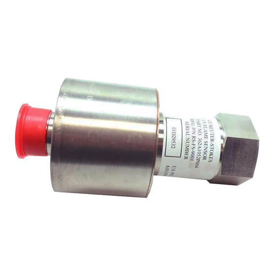
GE Reuter-Stokes FLAME TRACKER Operation & Maintenance Manual

GE Reuter-Stokes FLAME TRACKER Operation & Maintenance Manual

Sic two wire flame sensor (4-20 ma)

Advertisement

g
GE Reuter-Stokes
8499 Darrow Road
Twinsburg, OH 44087
TM
FLAME TRACKER
SiC TWO WIRE FLAME SENSOR (4-20 mA)
OPERATION & MAINTENANCE MANUAL
MODEL RS-FS-9001
REVISION M
MANUFACTURER: REUTER – STOKES
TWINSBURG, OH, USA
www.ge-mcs.com
GENERAL ELECTRIC COMPANY
Copyright 2016 GE Reuter-Stokes. All rights reserved

Advertisement

Table of Contents
loading
Need help?

Need help?

Do you have a question about the FLAME TRACKER and is the answer not in the manual?

Questions and answers

Summary of Contents for GE Reuter-Stokes FLAME TRACKER

  • Page 1 8499 Darrow Road Twinsburg, OH 44087 FLAME TRACKER SiC TWO WIRE FLAME SENSOR (4-20 mA) OPERATION & MAINTENANCE MANUAL MODEL RS-FS-9001 REVISION M MANUFACTURER: REUTER – STOKES TWINSBURG, OH, USA www.ge-mcs.com GENERAL ELECTRIC COMPANY Copyright 2016 GE Reuter-Stokes. All rights reserved...
  • Page 2 OTHERWISE. THIS DISCLAIMER APPLIES, WITHOUT LIMITATION, TO ANY DAMAGES OR INJURY ARISING FROM ANY FAILURE OF PERFORMANCE, ERROR, OMISSION, YOUR LOSS OF PROFITS, DESTRUCTION, AND ANY OTHER TANGIBLE OR INTANGIBLE LOSS. Copyright © 2016 General Electric Company. Contains GE Proprietary Information. Copyright 2016 GE Reuter-Stokes. All rights reserved...
  • Page 3: Revision History

    WRTR: DATE: 40293054 R. Martin 06/25/10 REV#: K ECN#: WRTR: DATE: 77469075 J. Hashmi 04/24/13 REV#: L ECN#: WRTR: DATE: 500000157848 J. Hashmi 12/18/15 REV#: M ECN#: WRTR: DATE: 500000204318 J. Hashmi 02/22/16 Copyright 2016 GE Reuter-Stokes. All rights reserved...
  • Page 4: Certification Information

    FS-9001OM – REV M Certification Information ATTENTION! The RS-FS-9001 Flame Tracker sensor complies with the following standards: Control Number 9900287 Class 1, Div. 2, Grp A,B,C,D T3 Class 1, Zone 2 AEx nA IIC T3 Gc ATEX / IECEx II 3 G...
  • Page 5: Table Of Contents

    3.3 CONNECTOR PINOUT ............................9 3.4 SENSOR CHECKOUT ............................9 3.5 CONTROLLER SETUP ............................9 MAINTENANCE ..............................10 4.1 WARNING ............................... 10 4.2 CAUTION ................................. 10 TROUBLESHOOTING ............................10 5.1 WARNING ............................... 10 5.2 CAUTION ................................. 10 Copyright 2016 GE Reuter-Stokes. All rights reserved...
  • Page 6: Introduction

    455F (235C) with specified water cooling Relative Humidity 100% Non-Condensing Process Pressure 400 psig (2.8 Mpa) 0.1 inches DA 10 – 40 Hz Vibration 8 G continuous 40 – 2000 Hz 14 G Peak Copyright 2016 GE Reuter-Stokes. All rights reserved...
  • Page 7: Interconnecting Cable Rs-E2-0285Pxxx Or 362A1053Pxxx

    36 gauge (0.127 mm) nickel plated copper braid Jacket Extruded PFA Armor Stainless steel braid Connector MIL-C-38999 series III, shell size 15, 5 #16 pins (only 3 pins are used) Operating Voltage (max) 300 vrms Temperature (max) 482F (250C) Copyright 2016 GE Reuter-Stokes. All rights reserved...
  • Page 8: Reference

    FS-9001OM – REV M 1.2 REFERENCE Copyright 2016 GE Reuter-Stokes. All rights reserved...
  • Page 9: General Description

    UV light present. Both power and signal are transmitted on the same two wires. The sensor can be powered from a dc voltage between 12 and 30 volts. The whole transducer is sealed and filled with dry argon. Copyright 2016 GE Reuter-Stokes. All rights reserved...
  • Page 10 FS-9001OM – REV M FIGURE 1 - SiC FLAME SENSOR WIRING DIAGRAM Copyright 2016 GE Reuter-Stokes. All rights reserved...
  • Page 11: Installation

    140 F (60 C). Air-cooling with pressurized air requires the use of Air-Cooling Can. GE Reuter-Stokes Part Number RS-E2- 0259 (GE Part Number 07482SOCNL44821P01). The Air-Cooing Can is installed in the same manner as the water-cooling coil.
  • Page 12 Note: 50 - 60 in. lbs = 5.6 - 6.8 Nm. When installing the Water Cooling Coil, ensure that the edge of the Sheet Metal Band is not in contact with the cooling tubes. This will ensure that no rubbing or fretting of the cooling tubes by the band’s edge will occur during turbine operation. Copyright 2016 GE Reuter-Stokes. All rights reserved...
  • Page 13: Electrical

    Reverse polarity will not damage the sensor. Signal cable from the junction box to the Controller should be 18 gauge (1.02 mm) twisted shielded pair. The extension cable from the junction box to the Controller is the customer’s responsibility. Copyright 2016 GE Reuter-Stokes. All rights reserved...
  • Page 14: Connector Pinout

    FS-9001OM – REV M The Flame Tracker™ is connected to the controller as a typical two wire current transmitter. It can be operated from any well-filtered dc supply from 12 volts to 30 volts. The supply should be capable of supplying 100 milliamps.
  • Page 15: Maintenance

    A shorter mount tube (PN# E1- of DLN1 turbines occur under high humidity 0058P002), is available from GE situations. Reuter Stokes and may improve this condition. Please contact GE Reuter Stokes for further information. Copyright 2016 GE Reuter-Stokes. All rights reserved...

This manual is also suitable for:

Rs-fs-9001

Table of Contents