
Related Manuals for Sutron Satlink 3

Summary of Contents for Sutron Satlink 3
- Page 1 Satlink 3 Models: SL3-1, SL3-SDI-1, SL3-XMTR-1 Operations & Maintenance Manual Part No. 8800-1207 Rev 8.04.2 November 3, 2016...
-
Page 2: Table Of Contents
Sutron Corporation Satlink Operations & Maintenance Manual, Rev 8.04.2 11/3/2016 pg. 2 TABLE OF CONTENTS 1. Scope of Supply............................... 8 1.1. Ordering Numbers ........................... 9 2. General Safety Information ........................... 10 3. Introduction ..............................11 3.1. SL3- 1 ..............................12 3.2. - Page 3 Sutron Corporation Satlink Operations & Maintenance Manual, Rev 8.04.2 11/3/2016 pg. 3 4.12. Connecting 0-5V Analog Sensors ......................25 4.13. Connecting 4-20ma Analog Sensors ....................... 25 4.14. Connecting Status Sensors ........................26 4.15. Connecting Potentiometer Sensors ....................... 27 4.16. Connecting mV Sensors .......................... 27 4.17.
- Page 4 Sutron Corporation Satlink Operations & Maintenance Manual, Rev 8.04.2 11/3/2016 pg. 4 5.12. Diagnostics Tab ............................54 5.13. Password Menu ............................57 5.14. Quick Status Dialog ..........................58 6. Operating Satlink ............................59 6.1. Creating a New Station in LinkComm ..................... 59 6.2.
- Page 5 Sutron Corporation Satlink Operations & Maintenance Manual, Rev 8.04.2 11/3/2016 pg. 5 9.6. Alarm Computation Details ........................93 9.7. Logging Settings ............................. 94 9.8. Measurement Setup Defaults ........................ 96 9.9. Measurement Calibration ........................96 9.10. Multiple Measurements Using the Same Sensor ................... 97 10.
- Page 6 15.4. Six Bit Binary Encoded Format ......................143 15.5. Pseudobinary over SMS ........................144 15.6. SHEF and SHEFFIX Data Format ......................144 15.7. Sutron Standard CSV ..........................146 15.8. ASCII Column ............................146 15.9. ASCII Sensor ............................147 15.10. TCP/IP Session ............................148 15.11.
-
Page 7: Sutron Corporation Satlink Operations & Maintenance Manual, Rev 8.04.2 11/3/2016
19.4. Setup of SDI sensors ..........................170 19.5. Useful SDI commands .......................... 170 20. Appendix A – Specifications ........................172 21. Appendix B – Sutron Customer Service Policy ..................... 175 22. Appendix C – Commercial Warranty ......................176 22.1. Sutron Manufactured Equipment ......................176 22.2. -
Page 8: Scope Of Supply
Sutron Corporation Satlink Operations & Maintenance Manual, Rev 8.04.2 11/3/2016 pg. 8 1. Scope of Supply SL3-1 GOES/METEOSAT/INSAT/GMS Satellite transmitter including 11 physical input channels (1xRS485, 2xSDI-12, 2xpulse/status, 2x5V analog, 3xDifferential Analog, 1x 4-20mA), 4 isolated switched supplies, 1 isolated non-switched... -
Page 9: Ordering Numbers
Sutron Corporation Satlink Operations & Maintenance Manual, Rev 8.04.2 11/3/2016 pg. 9 1.1. Ordering Numbers Model Description SL3-1 GOES/METEOSAT/INSAT Satellite transmitter with 11 physical input channels SL3-1-IR Base SL3-1 with Iridium option module installed SL3-1-IR-D Base SL3-1 with DOD flashed Iridium option module installed... -
Page 10: General Safety Information
Do not open Satlink. There are no user serviceable parts inside. Have a defective Satlink checked and repaired by the Sutron repair center. Do not attempt to repair Satlink yourself. Operate Satlink only with approved antenna connected. -
Page 11: Introduction
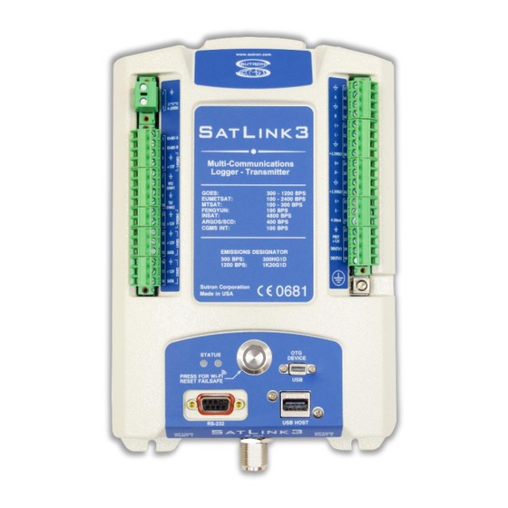
Satlink Operations & Maintenance Manual, Rev 8.04.2 11/3/2016 pg. 11 3. Introduction Sutron’s Satlink 3 is a datalogger with a built-in satellite transmitter that is especially designed for hydrometry, meteorology and environmental monitoring. It is available in three models: SL3-1, SL3-SDI-1, and SL3-XMTR-1. Satlink 3 can: ... -
Page 12: Sl3- 1
Sutron Corporation Satlink Operations & Maintenance Manual, Rev 8.04.2 11/3/2016 pg. 12 Expanded SDI-12 capacity with 2 independent SDI-12 inputs Optional cell/Iridium modems for redundant 2-way communications Expanded log from 120,000 to 1,000,000 readings, expandable to 1,000,000,000 readings (32 GB) via internal SDHC card ... -
Page 13: Sl3-Sdi-1
SL3-XMTR-1 is designed to connect to another logger via the RS232 port. The logger will setup the SL3-XMTR-1 and regularly transfer data to it for transmission. The logger may use Sutron’s Satlink Communicator Protocol (SCP) or command line protocol for setup and data transfer functions. -
Page 14: Status Leds
LinkComm software which will allow the user complete control over Satlink subject to the password protection in Satlink. The RS232 port also allows the connection of Sutron’s 8310, 9210 and Xpert loggers to Satlink. With this connection, the Sutron logger can use Satlink as transmitter to send data that it collects, rather than have Satlink collect the data. -
Page 15: Rf Output
Sutron Corporation Satlink Operations & Maintenance Manual, Rev 8.04.2 11/3/2016 pg. 15 automatically download all logged data since the last download and store the log on the flash drive. It will also store station setup and status on the flash drive. -
Page 16: Sl3-1 Left Terminal Strip
Sutron Corporation Satlink Operations & Maintenance Manual, Rev 8.04.2 11/3/2016 pg. 16 3.10. SL3-1 Left Terminal strip Two terminal strips built into SL3 provide the connections for sensors, and outputs. The table below describes the purpose of each connection on the left terminal strip. Additional information on using the connections is given in Chapter 4. -
Page 17: Sl3-1 Right Terminal Strip
Sutron Corporation Satlink Operations & Maintenance Manual, Rev 8.04.2 11/3/2016 pg. 17 3.11. SL3-1 Right Terminal Strip Two terminal strips built into Satlink provide the connections for sensors, and outputs. The table below describes the purpose of each connection on the left terminal strip.. Additional information on using the connections is given in Chapter 4. -
Page 18: Installing Satlink
Sutron Corporation Satlink Operations & Maintenance Manual, Rev 8.04.2 11/3/2016 pg. 18 4. Installing Satlink 4.1. Attaching SL3-1 Requirements of the intended installation site are: Sufficient protection from moisture for an IP 63 device. Proper space for the electrical cables ... -
Page 19: Attaching Sl3-Sdi-1 & Sl3-Xmtr-1
Sutron Corporation Satlink Operations & Maintenance Manual, Rev 8.04.2 11/3/2016 pg. 19 4.2. Attaching SL3-SDI-1 & SL3-XMTR-1 Requirements of the intended installation site are: Sufficient protection from moisture for an IP 51 device. Proper space for the electrical cables ... -
Page 20: Earth Ground Point
The transmitter must be connected to an approved antenna to operate with the selected satellite system. Sutron offers a variety of antennae including YAGI and dome types that provide between 3 and 11 dB gain. Satlink will adjust its transmission power based on the type of antenna connected. -
Page 21: Connecting The Gps Antenna
The GPS antenna connection is at the top of the SL3-1. On SL3-SDI-1, the SMA connector is to the right of the power connection. Sutron provides a GPS antenna with each Satlink. Satlink has special circuitry to detect whether the GPS antenna is connected. -
Page 22: Connecting Sdi-12 Sensors
Sutron Corporation Satlink Operations & Maintenance Manual, Rev 8.04.2 11/3/2016 pg. 22 A standard 12VDC lead-acid or Gel battery is typically used as the power source for SL3. Do not power SL3 off AC power supplies without additional precautions to ensure the power supply is properly rated and the system is enclosed in a fire protection cabinet. -
Page 23: Connecting Rs485 Sensors
Sutron Corporation Satlink Operations & Maintenance Manual, Rev 8.04.2 11/3/2016 pg. 23 4.8. Connecting RS485 Sensors SL3 supports RS485 sensors that use the SDI-12 protocol for its messaging. SL3 will not be able to read data from RS485 sensors that do not support SDI-12. -
Page 24: Connecting Pulse Sensors
Sutron Corporation Satlink Operations & Maintenance Manual, Rev 8.04.2 11/3/2016 pg. 24 4.10. Connecting Pulse Sensors SL3-1 supports up to two sensors with pulse output. The pulse output can come from a switch that is momentarily closed (as in most flow meters and tipping buckets) or it can come from a device that actively puts out pulses to represent the value to be measured. -
Page 25: Connecting 0-5V Analog Sensors
Sutron Corporation Satlink Operations & Maintenance Manual, Rev 8.04.2 11/3/2016 pg. 25 The pulse output sensors connect to the DIN #1 or DIN #2 inputs. DIN #1 supports sensors with a low level AC output (100 mVp-p) or high level output while DIN#2 supports only sensors with a high level output (switch closure, 0-3VDC, or 0-5VDC). -
Page 26: Connecting Status Sensors
Sutron Corporation Satlink Operations & Maintenance Manual, Rev 8.04.2 11/3/2016 pg. 26 The key settings for 4-20mA sensors connected to the 4-20mA input are: Measurement Type: Analog Analog Type: 4-20mA The built-in 4-20mA connection has an internal 200 ohm load consisting of transient protection and a precision 100 ohm sense resistor. -
Page 27: Connecting Potentiometer Sensors
Sutron Corporation Satlink Operations & Maintenance Manual, Rev 8.04.2 11/3/2016 pg. 27 4.15. Connecting Potentiometer Sensors A potentiometer connects to SL3 via the A or B analog channels as shown below. The key settings for potentiometer sensors are: Measurement Type: Analog ... -
Page 28: Connecting Thermistors
Sutron Corporation Satlink Operations & Maintenance Manual, Rev 8.04.2 11/3/2016 pg. 28 The key settings for mv output sensors are: Measurement Type: Analog Analog type: Diff C, D or E Input Range: 39mV, 312mV, 2.5V, 39mV w/Bias, 312mv w/Bias. -
Page 29: Connecting Thermocouples
Sutron Corporation Satlink Operations & Maintenance Manual, Rev 8.04.2 11/3/2016 pg. 29 Steinhart((10000)*X/(vref-X), A, B, C) (see table below for A, B, C) Note: The 10000 is the reference resistor value in ohms. Slope: 1.8; Offset: 32 to convert to Fahrenheit. - Page 30 Sutron Corporation Satlink Operations & Maintenance Manual, Rev 8.04.2 11/3/2016 pg. 30 The key settings for thermocouples are: Measurement Type: Analog Analog type: Diff C, D or E. Input Range: 39mV with Bias Equation: 24716*X+Terminal_temp {K type thermocouple, -8C to 64C} For more accurate results, here are some other K-Type Equations: Linear delta T range of ±...
-
Page 31: Connecting Strain Gauges
2.5VREF when you need a different excitation voltage for a sensor. The optional card (Sutron part 6461-1328) can be plugged into either Option port 1 or 2. The outputs have a range of 0 to 5VDC. The desired output is set via the menu on the options... -
Page 32: Connecting Prop/Vane Or Anemometer/Vane Wind Sensors
Sutron Corporation Satlink Operations & Maintenance Manual, Rev 8.04.2 11/3/2016 pg. 32 The PREF board has the following terminals: G1, E1, G2, E2 Where G1/G2 are grounds and E1/E2 are the PREF1 and PREF2 voltages. 4.21. Connecting Prop/Vane or Anemometer/Vane Wind... -
Page 33: Connecting Lufft Wind Sensors
Sutron Corporation Satlink Operations & Maintenance Manual, Rev 8.04.2 11/3/2016 pg. 33 DC high or AC low: AC low level (for unamplified RMYOUNG) Slope: Wind Speed Units Slope 0.098 knots 0.1904 0.2194 kph (km/h) 0.3528 To setup for wind vector measurements, go to 9.3.6... -
Page 34: Connecting Samplers Triggered By Stage
You can connect an external modem to SL3 and use it to communicate with SL3 remotely using LinkComm or other communication programs. The modem must be Sutron’s 8080-0005-1B modem with a special configuration saved in its profile. The modem will connect to the SL3 RS232 port via a male-male null modem cable. -
Page 35: Connecting External Cell Modems
1) Creating/selecting the script. Some readymade scripts are provided based on typical settings and common APNs. Go ahead and use ATT_script.txt, T-Mobile_script.txt, or Rogers_script.txt if you are using either of these providers. Otherwise, contact Sutron for help in creating the proper files for the modem. - Page 36 Sutron Corporation Satlink Operations & Maintenance Manual, Rev 8.04.2 11/3/2016 pg. 36 2) Load the script in to a thumb drive. The file must be copied in to the station folder, and must be renamed with the station as part of the file name. For instance if the station was named S01 then the file must be renamed "S01_script.txt"...
-
Page 37: Installing And Running Linkcomm
Installing the PC version of LinkComm The PC version of LinkComm is available for download from http://www.sutron.com/downloads.htm. The PC version is supported on Windows 7 and higher. After downloading LinkComm, run the program and follow the instructions on the screen. For Windows, extract all files to a folder on your computer. - Page 38 Sutron Corporation Satlink Operations & Maintenance Manual, Rev 8.04.2 11/3/2016 pg. 38 On small displays, the station list is hidden. Press < Stations to see the station list. To work with the selected station, press “Connect”. The software will use the assigned connection settings (USB, RS232, Modem, or Wi-Fi), to try to communicate with the site.
- Page 39 Sutron Corporation Satlink Operations & Maintenance Manual, Rev 8.04.2 11/3/2016 pg. 39 You can set the software to get recent data (5). “Get recent data on connect”, when checked, will cause LinkComm to download the last week of data for display in a graph on the dashboard tab, every time you connect to Satlink.
- Page 40 5.3.2.2. The Redirector Sutron provides a “redirector” service that can be used to access a Satlink station that uses a SIM card provided by Sutron. The IP addresses of these SIM cards are behind a firewall, and so need special steps to be taken for access.
- Page 41 Sutron Corporation Satlink Operations & Maintenance Manual, Rev 8.04.2 11/3/2016 pg. 41 Once the LinkComm session is complete, make sure to disconnect from Satlink's Wi-Fi hotspot. In order for LinkComm to connect to Satlink via Wi-Fi, the device that is running LinkComm must first connect to the Wi-Fi hotspot provided by Satlink.
-
Page 42: Main Menu
Sutron Corporation Satlink Operations & Maintenance Manual, Rev 8.04.2 11/3/2016 pg. 42 5.3.6. Working Offline To “work offline” means to make changes to the setup in LinkComm setup while disconnected from Satlink. You enter this mode by selecting “Work Offline” in the station view. The changes you make to the setup are automatically saved in LinkComm but not in the Satlink. - Page 43 About… Display a dialog showing information about LinkComm, including version Sutron Website… Visit the Sutron website Event Log… Show LinkComm event log. This is a text file showing diagnostic information about LinkComm operation. Exit Exit and close the LinkComm application. This item is not displayed...
-
Page 44: Station View
Sutron Corporation Satlink Operations & Maintenance Manual, Rev 8.04.2 11/3/2016 pg. 44 The following menu items are displayed in Station Detail View (i.e., when connected or working offline): Stations… Disconnect and return to the Stations List View Log In… LinkComm prompts for password and then attempts to log in to Satlink Change Password…... - Page 45 Sutron Corporation Satlink Operations & Maintenance Manual, Rev 8.04.2 11/3/2016 pg. 45 5.5.1. Connect Button The right header button is the “Connect Button”. It shows the status of the current connection from LinkComm to Satlink. The button has two possible states:...
- Page 46 Sutron Corporation Satlink Operations & Maintenance Manual, Rev 8.04.2 11/3/2016 pg. 46 Note: When the setup displayed by LinkComm is the same as the setup in Satlink, then we say the setups are “in-sync”. When the setups are not the same, the setup status button displays a warning sign, and you must send the setup to Satlink to get the setups “in-sync”.
- Page 47 Sutron Corporation Satlink Operations & Maintenance Manual, Rev 8.04.2 11/3/2016 pg. 47 To give a setup created by LinkComm to Satlink, you may either use the setup status button as described in the previous section, or select the Send Setup To Satlink item...
-
Page 48: Dashboard Tab
Sutron Corporation Satlink Operations & Maintenance Manual, Rev 8.04.2 11/3/2016 pg. 48 5.6. Dashboard Tab The Dashboard tab is the first tab displayed after you connect to Satlink. When LinkComm connects to Satlink, it retrieves the current station status, and current data values for measurements, and displays this data on the Dashboard. -
Page 49: Measurements Tab
Sutron Corporation Satlink Operations & Maintenance Manual, Rev 8.04.2 11/3/2016 pg. 49 5.6.1. Changing the Station Name The station name can only be changed from the Dashboard tab, and is actually the only setup item that can be changed from the Dashboard tab. To change the station name, press the blue “edit”... -
Page 50: Data Tab
Sutron Corporation Satlink Operations & Maintenance Manual, Rev 8.04.2 11/3/2016 pg. 50 5.8. Data Tab The data tab shows historical measurement readings made by Satlink. If recent data was downloaded when connecting to Satlink, the graph displays this data the first time you select the Data tab. -
Page 51: Telemetry Tab
Sutron Corporation Satlink Operations & Maintenance Manual, Rev 8.04.2 11/3/2016 pg. 51 5.9. Telemetry Tab The Telemetry tab is used to configure a station for Environmental Satellite (GOES), Iridium or Cellular communications. The contents of the tab differ for each telemetry type. -
Page 52: Gps Tab
Sutron Corporation Satlink Operations & Maintenance Manual, Rev 8.04.2 11/3/2016 pg. 52 The status text is retrieved from Satlink the first time you display the telemetry tab, and can be refreshed as needed on demand. Please see the section for more info. -
Page 53: Other Setup Tab
Sutron Corporation Satlink Operations & Maintenance Manual, Rev 8.04.2 11/3/2016 pg. 53 In order to give the user a better idea of the quality of the GPS signal, Satlink Logger provides messages that indicate how long the GPS module was powered before a time sync was initiated. -
Page 54: Diagnostics Tab
Sutron Corporation Satlink Operations & Maintenance Manual, Rev 8.04.2 11/3/2016 pg. 54 See section for more information setting in this page. THER ETUP Iridium and Cell Telemetry types offer Iridium Diags and Cell Diags buttons which provides diagnostics information on the modems. Please see the section for details. - Page 55 Sutron Corporation Satlink Operations & Maintenance Manual, Rev 8.04.2 11/3/2016 pg. 55 5.12.1. Firmware Versions and Diagnostics The top two text areas on the Diagnostics tab display information about the firmware installed in the connected Satlink. The Firmware Versions section displays the current versions of firmware installed in Satlink. If LinkComm detects a newer version of firmware is available, this text area contains a message saying such.
- Page 56 5.12.5. Firmware Upgrade The software running in Satlink can be upgraded. The latest version of Satlink firmware is delivered as part of the LinkComm download package obtained from the Sutron web site. LinkComm may be downloaded from http://www.sutron.com/downloads.htm (search on “LinkComm”).
-
Page 57: Password Menu
Sutron Corporation Satlink Operations & Maintenance Manual, Rev 8.04.2 11/3/2016 pg. 57 You can also upgrade the firmware via USB. See section 6.15.3 Update the Firmware via USB Thumb Drive. 5.12.6. Setting to Factory Defaults Setting the station to factory defaults will permanently erase all setup and status. The setup will be set to defaults. -
Page 58: Quick Status Dialog
Sutron Corporation Satlink Operations & Maintenance Manual, Rev 8.04.2 11/3/2016 pg. 58 5.14. Quick Status Dialog When disconnecting from a Satlink3 station, LinkComm displays a Quick Status dialog, containing a summary of important status information. The dialog displays system time and battery voltage information at the top. The scrollable list of... -
Page 59: Operating Satlink
Sutron Corporation Satlink Operations & Maintenance Manual, Rev 8.04.2 11/3/2016 pg. 59 6. Operating Satlink The following scenarios describe how to perform some common functions with a Satlink. They assume that Satlink is powered up and that LinkComm is running and can connect to the station via USB, RS232, or Wi-Fi. -
Page 60: Examine Measurements
Sutron Corporation Satlink Operations & Maintenance Manual, Rev 8.04.2 11/3/2016 pg. 60 6.5. Examine Measurements Go to the Dashboard Press “Refresh Status” to see latest data from each measurement Right click and select “Refresh recent data” to update graphs. -
Page 61: Viewing/Clearing The Status
Sutron Corporation Satlink Operations & Maintenance Manual, Rev 8.04.2 11/3/2016 pg. 61 When download is complete, press “Save File…”. Note the file is named by the end time in the span. 6.12. Viewing/Clearing the Status Go to Dashboard ... -
Page 62: Usb Thumb Drive (Flash Drive) Operation
Sutron Corporation Satlink Operations & Maintenance Manual, Rev 8.04.2 11/3/2016 pg. 62 sky so the GPS can track the satellites. Satlink will frequently update its clock to the time reported by the GPS module. Should GPS fail for any reason, the Satlink will continue to operate the transmitter for up to 30 days. - Page 63 USB thumb drive. Copy the setup file to a USB drive and place in in the \Sutron\Satlink\StationName directory, where StationName is the current name of the station that will have its setup updated.
-
Page 64: Security
Sutron Corporation Satlink Operations & Maintenance Manual, Rev 8.04.2 11/3/2016 pg. 64 7. Security Satlink provides means of protection against unwanted access. Password protection is at the heart of the security. Whether accessing Satlink with a USB cable, an RS232 cable, via the Wi-Fi hotspot, through a USB thumb drive, over Iridium SBD messages, over cell TCP/IP, or over cell SMS messages, password protection guards access to Satlink. - Page 65 Sutron Corporation Satlink Operations & Maintenance Manual, Rev 8.04.2 11/3/2016 pg. 65 Read access is the lowest access level. A customer with read access may not make any changes to the system. Read access allows one to view measurement readings, view status, and view setup, and the like.
- Page 66 Sutron Corporation Satlink Operations & Maintenance Manual, Rev 8.04.2 11/3/2016 pg. 66 7.2.3. Working with a Password Protected Station If LinkComm is used to connect to a password protected station, LinkComm will automatically prompt for a password. When sending a message to a password protected station, the first line of the message must have the login command LOGIN=XXX, where XXX is the password.
-
Page 67: Satlink Setup
Sutron Corporation Satlink Operations & Maintenance Manual, Rev 8.04.2 11/3/2016 pg. 67 8. Satlink Setup Satlink operation is controlled by its setup. The user has the option of changing any part of the setup. The setup is stored in non-volatile memory and will not be affected when the unit loses power. -
Page 68: Measurement Setup
Sutron Corporation Satlink Operations & Maintenance Manual, Rev 8.04.2 11/3/2016 pg. 68 9. Measurement Setup The measurements tab in LinkComm is where the measurement setups are managed. A measurement is the process of collecting data from a sensor. SL3 provides the ability to establish up to 32 measurements, each with its unique settings. - Page 69 Sutron Corporation Satlink Operations & Maintenance Manual, Rev 8.04.2 11/3/2016 pg. 69 The following is an example of a template for an air temperature/relative humidity sensor. To use the template: Use the right and left arrows on the sides of the sensor picture to scroll between the available sensor templates.
- Page 70 Sutron Corporation Satlink Operations & Maintenance Manual, Rev 8.04.2 11/3/2016 pg. 70 For details on the different measure types, please see section 9.3.1. 9.1.4. Label User set name given to measurement, up to 11 bytes. This is used to identify and differentiate measurements.
-
Page 71: Schedule
Sutron Corporation Satlink Operations & Maintenance Manual, Rev 8.04.2 11/3/2016 pg. 71 9.1.10. Icon You can select an Icon for the measurement. The icon will show on the dashboard and measurement list. Press “Change” to choose an image in the computer or take a picture. - Page 72 Sutron Corporation Satlink Operations & Maintenance Manual, Rev 8.04.2 11/3/2016 pg. 72 Setting the Averaging Time to 00:00:00 (zero) disables averaging -- one sample is to be collected. This is the default setup. If Averaging Time is zero, Sampling Interval and Subsamples will not be shown in the setup.
- Page 73 Sutron Corporation Satlink Operations & Maintenance Manual, Rev 8.04.2 11/3/2016 pg. 73 01:00:00 all four samples are averaged and the result is logged with the 01:00:00 timestamp The Results field will be shown only if averaging is enabled. If it is enabled, you can select average, minimum, maximum, running average, running minimum, running maximum to be the logged result value.
- Page 74 Sutron Corporation Satlink Operations & Maintenance Manual, Rev 8.04.2 11/3/2016 pg. 74 12:05 Sample sensor (reading = 5.0). Compute and log 5 minute average. Result = 3.0, computed as (1.0+2.0+3.0+4.0+5.0)/5; 12:06 Sample sensor (reading = 6.0). Compute and log 5 minute average. Result = 4.0, computed as (2.0+3.0+4.0+5.0+6.0)/5;...
-
Page 75: Configuration Settings
Sutron Corporation Satlink Operations & Maintenance Manual, Rev 8.04.2 11/3/2016 pg. 75 Likewise, at 17:00, the measurement that started at 16:00 is complete. The maximum happened at 16:12 and the minimum at 16:39. When it comes time to transmitting minimum and maximum results, Satlink will include a unique timestamp with each value transmitted. - Page 76 Sutron Corporation Satlink Operations & Maintenance Manual, Rev 8.04.2 11/3/2016 pg. 76 Precipitation rate, unlike precipitation accumulation, measures the precipitation that has occurred since the last measurement. So, if the measurement interval is 15 minutes, this measurement will report the rainfall in the last 15 minutes only.
- Page 77 You may use SWD#1 12V instead of SDI-12 Power to supply power to the SDI-12 sensor as long as the sensor does not require to be powered on all the time. Some sensors (such as the Sutron SDR) need to be powered on all the time and will not work correctly if powered from the Switched Power line.
- Page 78 Sutron Corporation Satlink Operations & Maintenance Manual, Rev 8.04.2 11/3/2016 pg. 78 9.3.3.6. SDI-12 Command Utility The SDI-12 command utility dialog is used to send SDI-12 commands to sensors connected to Satlink. It can also be used to quickly find what sensors are connected to the SDI-12 bus.
- Page 79 Sutron Corporation Satlink Operations & Maintenance Manual, Rev 8.04.2 11/3/2016 pg. 79 9.3.4.2. 0-5V A and 0-5V B Connection A: 0-5V A Terminal #36 and Signal ground Terminal #37 Connection B: 0-5V B Terminal #34and Signal ground Terminal #35 Inputs 0-5V A and 0-5B are designed to be general purpose 0-5 Volt DC input. While sometimes referred to as a single ended input, it is designed to measure voltage with respect to analog signal ground.
- Page 80 Sutron Corporation Satlink Operations & Maintenance Manual, Rev 8.04.2 11/3/2016 pg. 80 While the differential inputs are capable of reading negative voltages, it is important to keep the voltages with respect to ground within in the common mode input range of 0.5 to 3.7 volts. In the case of a bridge sensor, by using the vref and signal ground to establish the voltage on the network, you are assured of having a positive voltage with respect to signal ground.
- Page 81 Sutron Corporation Satlink Operations & Maintenance Manual, Rev 8.04.2 11/3/2016 pg. 81 current loop, then only 8.5 volts will be supplied to the sensor at max sensor current output. Therefore if a full 12 volts is necessary for the sensor, an external loop supply will be necessary or alternately the sensor may be wired to a single ended voltage input with the use of an external 100 Ohm accurate and stable resistor also attached to the voltage input port.
- Page 82 Sutron Corporation Satlink Operations & Maintenance Manual, Rev 8.04.2 11/3/2016 pg. 82 Use slope/offset/equation to properly scale the direction to degrees. Disable logging for the data (log interval = 24:00:00) Disable transmission of the data (TX Data Content = Exclude) ...
- Page 83 Sutron Corporation Satlink Operations & Maintenance Manual, Rev 8.04.2 11/3/2016 pg. 83 Max Direction Count Time of Max Speed After picking the result, set the schedule for the calculation. The following schedule computes a 15 minute average of wind data collected every 60 seconds. The sampling interval (e.g. 60 below) must match with the interval set for the speed and direction sensors setup separately.
- Page 84 Sutron Corporation Satlink Operations & Maintenance Manual, Rev 8.04.2 11/3/2016 pg. 84 Mean Magnitude Unit – This is the vector average of the wind speed using unit vectors. The mean magnitude unit of 5mph at 0 for 1 hour and 100mph at 90...
- Page 85 Sutron Corporation Satlink Operations & Maintenance Manual, Rev 8.04.2 11/3/2016 pg. 85 STD Speed Scalar – This is the standard deviation of the scalar wind speed. STD Direction Unit – This is the standard deviation of the direction unit. STD Direction Wind – This is the standard deviation of the direction wind.
- Page 86 Sutron Corporation Satlink Operations & Maintenance Manual, Rev 8.04.2 11/3/2016 pg. 86 Counter type readings may also be limited by a rollover value. With rollover set to 0, the counter will increase until it reaches 4,294,967,296 (2^32). With rollover set to a non-zero value, the counter will be reset to 0 when it exceeds the rollover value.
-
Page 87: Processing Settings
Sutron Corporation Satlink Operations & Maintenance Manual, Rev 8.04.2 11/3/2016 pg. 87 Measurement Interval: 1 hour Averaging Time: 1 hour Sampling Interval: 1 second Measurement M2 (used for Daily Temperature) Measurement Type: Meta Meta Index: 1 (meaning it refers to measurement M1) ... - Page 88 Sutron Corporation Satlink Operations & Maintenance Manual, Rev 8.04.2 11/3/2016 pg. 88 Offset as 1, the final reading would be 11 (2*5 + 1). The raw reading would be 2. If Details is enabled, the raw reading is displayed on the command line by typing MEAS or LAST.
- Page 89 Sutron Corporation Satlink Operations & Maintenance Manual, Rev 8.04.2 11/3/2016 pg. 89 The following functions are available:...
- Page 90 Sutron Corporation Satlink Operations & Maintenance Manual, Rev 8.04.2 11/3/2016 pg. 90 SIN, COS, TAN, ARCTAN, eg COS(90) = 0 SQRT is square root, eg SQRT(9) = 3 To raise a number to a power, multiply it by itself. So, for example, to find x squared, input x*x.
-
Page 91: Alarm Settings
Sutron Corporation Satlink Operations & Maintenance Manual, Rev 8.04.2 11/3/2016 pg. 91 At this point, M1 = 2.0, Prev1 = 1.0, DeltaT1 = 300 12:15:00 Measurement M1 has made a reading of 3.0 At this point, M1 = 3.0, Prev1 = 2.0, DeltaT1 = 300 Comments can be contained within braces { }. - Page 92 Sutron Corporation Satlink Operations & Maintenance Manual, Rev 8.04.2 11/3/2016 pg. 92 Satlink can be set up to send transmissions when it goes into alarm. Alternatively, Satlink can be set up to make a transmission when it goes into alarm and to make another transmission when it goes out of alarm.
-
Page 93: Alarm Computation Details
Sutron Corporation Satlink Operations & Maintenance Manual, Rev 8.04.2 11/3/2016 pg. 93 9.5.4. Alarm Tx Mode Alarm Tx Mode determines whether transmissions are made when the station goes (into alarm) or (when it goes into and out of alarm). ... -
Page 94: Logging Settings
Sutron Corporation Satlink Operations & Maintenance Manual, Rev 8.04.2 11/3/2016 pg. 94 9.6.1. Hi Alarm When the Alarm Type is set to Hi, if the sensor reading is greater than or equal to Alarm Threshold, the station goes into alarm. - Page 95 Sutron Corporation Satlink Operations & Maintenance Manual, Rev 8.04.2 11/3/2016 pg. 95 LinkComm provides a Log All checkbox: when checked Satlink will measure and log at the Measurement Interval. Having a Logging Interval that is shorter than the Measurement Interval is a bad setup.
-
Page 96: Measurement Setup Defaults
Sutron Corporation Satlink Operations & Maintenance Manual, Rev 8.04.2 11/3/2016 pg. 96 Timeline: 11:00 measure and log data 11:15 measure and log data 11:30 measure and log data 11:45 measure and log data 11:50 transmission Setup options: ... -
Page 97: Multiple Measurements Using The Same Sensor
Sutron Corporation Satlink Operations & Maintenance Manual, Rev 8.04.2 11/3/2016 pg. 97 Measurement M1 STAGE set to 12.000 04/18/2012,13:19:49,STAGE,8.119 04/18/2012,13:19:49,Calibration,1 04/18/2012,13:19:49,STAGE,12.000 9.10. Multiple Measurements Using the Same Sensor You can set up multiple measurements with the same input. For example, to log the daily rainfall and the rainfall during the last hour, set up two measurements: one as a precipitation rate with an interval of one hour, and another as precipitation rate with an interval of one day. -
Page 98: Telemetry Setup
Sutron Corporation Satlink Operations & Maintenance Manual, Rev 8.04.2 11/3/2016 pg. 98 10. Telemetry Setup Satlink has a built-in environmental satellite transmitter certified by NESDIS, Eumetsat, Insat and other satellite agencies. These satellites provide reliable one way communications of data from remote locations to receive stations/computer systems around the world. - Page 99 Sutron Corporation Satlink Operations & Maintenance Manual, Rev 8.04.2 11/3/2016 pg. 99 Please note that the transmission data content is governed by measurement setup. Please see the section for details. RANSMISSION ONTENT ETTINGS The column on the right has two main sections – Telemetry Setup and Telemetry Status. You...
-
Page 100: Environmental Scheduled Transmissions
Sutron Corporation Satlink Operations & Maintenance Manual, Rev 8.04.2 11/3/2016 pg. 100 10.2. Environmental Scheduled Transmissions This section describes Environmental Satellite Scheduled transmissions. Scheduled transmissions happen periodically at a fixed time. TX1 setup is reserved for scheduled transmissions using an environmental satellite. Additional scheduled transmissions may be setup on TX3 and TX4. - Page 101 Sutron Corporation Satlink Operations & Maintenance Manual, Rev 8.04.2 11/3/2016 pg. 101 Window center enable causes Satlink to delay a transmission that does not last the entire allowed length so it is centered during the assigned window. Window centering helps the satellite system to operate more efficiently.
- Page 102 Sutron Corporation Satlink Operations & Maintenance Manual, Rev 8.04.2 11/3/2016 pg. 102 “ASCII Sensor” mode formats each sensor reading into four digits after multiplying the reading by 100. No decimal point is used in this format. The specifics of formatting are covered in greater detail in...
- Page 103 Sutron Corporation Satlink Operations & Maintenance Manual, Rev 8.04.2 11/3/2016 pg. 103 10.2.7.2. Battery Voltage The battery reading appended is the battery under load reading in Volts made at the start of the PREVIOUS environmental satellite transmission. The initial transmission will have append minus one (-1.0).
-
Page 104: Random Transmissions
Sutron Corporation Satlink Operations & Maintenance Manual, Rev 8.04.2 11/3/2016 pg. 104 :BL 11.99 N45o27'28.47"W122o43'59.08" :NAME Small Creek :AMPTEMP 25.53C :PWR 1.6/0.0 :YD 172100 :SN 00001 :GOOD/BAD 19350/2 For append option details in other formats, please take a look at section... -
Page 105: Iridium Setup
Sutron Corporation Satlink Operations & Maintenance Manual, Rev 8.04.2 11/3/2016 pg. 105 transmissions in the burst is controlled by the setting Number of Txs per Burst. The default value is three, meaning Satlink will fire off three transmissions once the station goes into alarms. - Page 106 Sutron Corporation Satlink Operations & Maintenance Manual, Rev 8.04.2 11/3/2016 pg. 106 10.4.2.1. Iridium Scheduled Iridium Scheduled transmissions are much like Environmental Satellite Scheduled transmissions: Settings Scheduled Time and Scheduled Interval are used to determine when and how often Iridium transmissions are to happen. However, the choice of when to transmit is entirely up to the user.
-
Page 107: Cell Setup
Sutron Corporation Satlink Operations & Maintenance Manual, Rev 8.04.2 11/3/2016 pg. 107 10.4.3.2. Iridium Msg Interval Please note that even with Listening disabled, Satlink will still check for messages periodically. A message checks happens with every transmission. If scheduled transmissions are disabled, message checking still happens every Msg Interval. - Page 108 Sutron Corporation Satlink Operations & Maintenance Manual, Rev 8.04.2 11/3/2016 pg. 108 Please make sure to read the section for additional information. ELLULAR ELEMETRY A lot of the telemetry settings for cell are similar to those for Iridium and Environmental Satellites.
- Page 109 Sutron Corporation Satlink Operations & Maintenance Manual, Rev 8.04.2 11/3/2016 pg. 109 10.5.2.4. Max Tx Time This value dictates how long Satlink will keep trying to reach the cellular network. If a connection is not made during this time, Satlink will give up on the transmission and mark it as failed.
- Page 110 Sutron Corporation Satlink Operations & Maintenance Manual, Rev 8.04.2 11/3/2016 pg. 110 10.5.2.1. Cell Listening If enabled, Cell Listening will cause Satlink to keep the cellular modem on all the time. This makes it possible to connect to Satlink with LinkComm over the internet at any time. However, it significantly increases the power consumption.
-
Page 111: Telemetry Status
The telemetry status does will not update automatically. The “refresh” control retrieves from Satlink current information. 10.6.2. Clear Counts This control clears the succeeded and failed counts. Sutron recommends clearing the counts during each field visit. 10.6.3. Transmit Now Transmit Now causes Satlink to initiate a transmission on the selected setup (TX1, TX2, …). - Page 112 This feature causes Satlink to send an Environmental Satellite transmission on the GOES satellite using Sutron’s allocated Channel and Satellite ID. The intention is to allow the installer to test out that a station is working correctly without having to wait for the allocated Scheduled Transmission time slot.
- Page 113 Sutron Corporation Satlink Operations & Maintenance Manual, Rev 8.04.2 11/3/2016 pg. 113 This feature only shows for Environmental Satellite Radio Type. 10.6.6. Antenna Aim This is another feature of Environmental Satellite telemetry. It helps the installer correctly point the satellite antenna. The system will compute the antenna azimuth and elevation based up the current location of Satlink (provided by Satlink’s GPS) and the Satellite type (chosen by the...
- Page 114 Sutron Corporation Satlink Operations & Maintenance Manual, Rev 8.04.2 11/3/2016 pg. 114 10.6.7. Radio Diags This button is used for Iridium and Cell telemetry setups. Pressing it will bring up a Diagnostics window that shows the current status of the Iridium or Cell modem, along with signal strength information.
-
Page 115: Other Setup
Sutron Corporation Satlink Operations & Maintenance Manual, Rev 8.04.2 11/3/2016 pg. 115 11. Other Setup The Other Setup tab provides settings for Wi-Fi, Logging, Digital Output DOUT and Modbus RS- 485. The settings for each is described below. 11.1. Wi-Fi The Wi-Fi section controls the operation of the Wi-Fi hot spot built into SL3. -
Page 116: Log Daily Values
Sutron Corporation Satlink Operations & Maintenance Manual, Rev 8.04.2 11/3/2016 pg. 116 The Wi-Fi hotspot is turned on for 10 minutes: at boot up when the station is connected to, whether via USB, over the modem, or over Wi-Fi ... - Page 117 2.5VREF when you need a different excitation voltage for a sensor. The optional card (Sutron part 6461-1328) can be plugged into either Option port 1 or 2. Note: You must issue the command OPTION PORT 1 = PREF (or OPTION PORT 2 = PREF) when you first install the PREF card in SL3.
-
Page 118: Output
Sutron Corporation Satlink Operations & Maintenance Manual, Rev 8.04.2 11/3/2016 pg. 118 GND, PREF1, GND, PREF2 11.4. Output Satlink includes two digital output labeled as DOUT 1 and DOUT2. The digital output may be activated via several means. Manually via command line. A command may be sent using LinkComm by directly connecting to Satlink via USB, sending GPRSLink an SMS, sending an email to an IRIDIUMLink, or via any other means of connecting to Satlink. -
Page 119: Cutoff
Sutron Corporation Satlink Operations & Maintenance Manual, Rev 8.04.2 11/3/2016 pg. 119 Command line access to output 1: OUTPUT1 tells whether the output is currently on. Satlink's possible replies: Output1 is NOT active Output1 is ACTIVE OUTPUT1 ON turns on the output ... -
Page 120: Iridium
Sutron Corporation Satlink Operations & Maintenance Manual, Rev 8.04.2 11/3/2016 pg. 120 Cutoff Temp Tx High = 85.0 C, Range (40.0, 100.0) Cutoff Temp Tx Low = -45.0 C, Range (-80.0, -20.0) 11.6. Iridium Please see the section for a description of these settings. -
Page 121: Telemetry
Sutron Corporation Satlink Operations & Maintenance Manual, Rev 8.04.2 11/3/2016 pg. 121 12. Telemetry 12.1. Iridium Telemetry Satlink may be equipped with an optional Iridium module. The module is plug and play and fits into one of the two option ports found on SL3-1. When so equipped, Satlink is capable of sending transmissions and receiving messages using the Iridium satellite network. - Page 122 Sutron Corporation Satlink Operations & Maintenance Manual, Rev 8.04.2 11/3/2016 pg. 122 The antenna-aiming feature can aid in correct station setup. It will show the current signal strength. Signal strength ranges from 0 (no signal) to 5 (excellent signal). ...
- Page 123 Sutron Corporation Satlink Operations & Maintenance Manual, Rev 8.04.2 11/3/2016 pg. 123 If your station is set up to make transmissions every 30 minutes, that means that it will take up to 30 minutes for Satlink to receive any messages sent to it. If that is too long, you may consider turning on Listening.
-
Page 124: Cellular Telemetry
Sutron Corporation Satlink Operations & Maintenance Manual, Rev 8.04.2 11/3/2016 pg. 124 The email's subject must be the IMEI of the Iridium modem. The IMEI may be seen by pressing the Radio Diags window of LinkComm’s Telemtry tab. Each transmission made by Satlink over Iridium will be stamped with its unique IMEI. -
Page 125: Missing Data Retrieval
An Satlink can be set up to always be listening, which means that it will act as a server, accepting TCP/IP incoming connections. Sutron's AutoPoll PC software can periodically reach out to a listening Satlink station and collect sensor data from Satlink. In the listening mode, Satlink will keep the modem on at all times, resulting in higher power consumption. - Page 126 Sutron Corporation Satlink Operations & Maintenance Manual, Rev 8.04.2 11/3/2016 pg. 126 12.3.2. Remote Data Retrieval Environmental Satellite transmissions are one way transmissions. If the only radio that Satlink is equipped with is the Environmental Satellite radio, there is not a way of retrieving data remotely.
- Page 127 Sutron Corporation Satlink Operations & Maintenance Manual, Rev 8.04.2 11/3/2016 pg. 127 A note about timestamps in the repeat Tx data: The timestamps are the same as if the Tx were made at the provided time, rather than indicating the true age of the data. This meas that the sensor data in the Tx is exactly the same as that of the Tx made in real time (which is 2016/6/20 23:00:30 in the example above).
-
Page 128: Logging
Satlink logs events such as power up, log download, and setup change. When downloaded, the data is presented in Sutron Standard CSV format. It is a format common to current Sutron products. A log entry looks like this: 04/02/2012,09:25:00,STAGE,20.50,FT,G ... -
Page 129: Log Events
Sutron Corporation Satlink Operations & Maintenance Manual, Rev 8.04.2 11/3/2016 pg. 129 You can download the whole log or only parts of it. You may specify the start date and optionally the end date for the downloaded data. You may also ask for data from the last X days. - Page 130 Sutron Corporation Satlink Operations & Maintenance Manual, Rev 8.04.2 11/3/2016 pg. 130 Minimum and maximum values are logged at the time the minimum or maximum occurs, not when the measurement was scheduled. This provides knowledge of the exact time the...
-
Page 131: Errors
Sutron Corporation Satlink Operations & Maintenance Manual, Rev 8.04.2 11/3/2016 pg. 131 14. Errors During operation, Satlink may notice system errors. If it does, it will blink the red LED on the front panel. To see the error details, check the status with LinkComm. Via command line, type STATUS to see any potential errors. -
Page 132: System Errors
Sutron Corporation Satlink Operations & Maintenance Manual, Rev 8.04.2 11/3/2016 pg. 132 14.2.3. Sampling Too Short This happens when the sensor response time is longer than the sampling interval. SDI-12 readings are a good example: if a sensor requires 10 seconds to produce a reading, and the sampling interval is 10 seconds, this error gets set. - Page 133 This error is recorded if any hardware issues were noted since boot up. The errors will also be placed in the log. Every hardware error has a code logged with it. A hardware error usually indicates a serious problem with the unit. Contact Sutron customer support at 703 406 2800 for help with hardware errors.
-
Page 134: Transmission Data Formats
Sutron Corporation Satlink Operations & Maintenance Manual, Rev 8.04.2 11/3/2016 pg. 134 15. Transmission Data Formats 15.1. Pseudobinary B Data Format This format is based on GOES Pseudobinary format. It is used when the user selects Pseudobinary B as the choice for Tx Format. The format uses ASCII characters. Three bytes are used for each data value. - Page 135 Sutron Corporation Satlink Operations & Maintenance Manual, Rev 8.04.2 11/3/2016 pg. 135 Field Pseudobinary B for Scheduled and Alarm Txs Minutes longitude = 7th-byte AND 63 Seconds longitude = 8th-byte AND 63 For example BAAODAXe would be decoded as Lat 39o 1' 15" Long 77o 24' 37"...
- Page 136 Sutron Corporation Satlink Operations & Maintenance Manual, Rev 8.04.2 11/3/2016 pg. 136 15.1.1.1. Pseudobinary B Random Example Here is an example random transmission with three active measurements; each one is set to include two readings: 2@@Gt@Gs@Sx@Sr@@i@@iEXTBAAODAXe@GL Decoding the message Pseudobinary values...
- Page 137 Sutron Corporation Satlink Operations & Maintenance Manual, Rev 8.04.2 11/3/2016 pg. 137 Field Pseudobinary B for Scheduled and Alarm Txs transmitted will be value * 10^RightDigits. The string /// will be sent if the data was never measured or was erased.
- Page 138 Sutron Corporation Satlink Operations & Maintenance Manual, Rev 8.04.2 11/3/2016 pg. 138 Field Pseudobinary B for Scheduled and Alarm Txs TEMP DURING LAST Tx [OPTIONAL] TX TIME [OPTIONAL] SERIAL NO [OPTIONAL] TX COUNT [OPTIONAL]...
-
Page 139: Pseudobinary C Data Format
Sutron Corporation Satlink Operations & Maintenance Manual, Rev 8.04.2 11/3/2016 pg. 139 15.1.2.1. Pseudobinary B Scheduled Example Here is a transmission with three active measurements; each one is set to include two readings: B1@@Gt@Gs@Sx@Sr@@i@@iEXTLBAAODAXe@R@A Decoding the message Pseudobinary values Decoded... - Page 140 All the required values for one sensor (most recent first) before proceeding to the next measurement. This format is similar to that used by the Sutron Satlink but different from the 8210. There will be 3 bytes of encoded data for every sensor reading.
-
Page 141: Pseudobinary D Data Format
Sutron Corporation Satlink Operations & Maintenance Manual, Rev 8.04.2 11/3/2016 pg. 141 Pseudobinary Decoded into Completely decoded Description values decimal Denotes Pseudobinary C format Scheduled transmission Delimiter for next measurement Measurement M1 June 14th M1 day of the year of the most recent reading. For 2013, it is June 14th. - Page 142 All the required values for one sensor (most recent first) before proceeding to the next measurement. This format is similar to that used by the Sutron Satlink but different from the 8210. There will be 3 bytes of encoded data for every sensor reading.
-
Page 143: Six Bit Binary Encoded Format
Sutron Corporation Satlink Operations & Maintenance Manual, Rev 8.04.2 11/3/2016 pg. 143 Pseudobinary Decoded Completely Description values into decimal decoded Denotes Pseudobinary D format Retransmission Nov 14th Day of the year of the most recent reading. For 2014, it is Nov 14th. -
Page 144: Pseudobinary Over Sms
15.6. SHEF and SHEFFIX Data Format SHEF is a format that is commonly used by Sutron's Satlink satellite transmitter. It is an ASCII format that is easy to read and contains some self-descriptive information. The format of the transmission data is: : <LABEL1>... - Page 145 Sutron Corporation Satlink Operations & Maintenance Manual, Rev 8.04.2 11/3/2016 pg. 145 LABEL This is the Label entered as a part of the setup for each measurement. The label can be a SHEF two-character parameter code such as HF for gauge height or PC for cumulative precipitation or it can be any string you enter.
-
Page 146: Sutron Standard Csv
15.7. Sutron Standard CSV Logs downloaded from Satlink will be in the Sutron Standard CSV format. It is possible to transmit data in the CSV format. However, CSV messages are too large for most applications and are generally used to help set up a station. -
Page 147: Ascii Sensor
Sutron Corporation Satlink Operations & Maintenance Manual, Rev 8.04.2 11/3/2016 pg. 147 <CRLF> Meas1_Data(1) Meas2_Data(1) ... MeasN_Data(1)<CRLF> Meas1_Data(2) Meas2_Data(2) ... MeasN_Data(2)<CRLF> Meas1_Data(n) Meas2_Data(n) ... MeasN_Data(n)<CRLF> <CRLF> is a carriage return, line feed Meas1_Data()..MeasN_Data are the data from the active measurements included in the transmission. -
Page 148: Tcp/Ip Session
Sutron Corporation Satlink Operations & Maintenance Manual, Rev 8.04.2 11/3/2016 pg. 148 Range of transmitted data is 0 to 9999 (numbers out of range are transmitted as 0000 or 9999). This means that the sensor data should be between 0 and 99.99 before formatting. -
Page 149: Iridium Telemetry Header
Sutron Corporation Satlink Operations & Maintenance Manual, Rev 8.04.2 11/3/2016 pg. 149 15.10.1. Course of Events 1. Satlink connects to main or backup server. 2. Satlink sends Session Type Code<cr> (see below.) 3. Satlink sends Station Name<cr>. 4. Satlink sends Report Type Code<cr> to indicate purpose of connection (see below.) 5. - Page 150 Sutron Corporation Satlink Operations & Maintenance Manual, Rev 8.04.2 11/3/2016 pg. 150 them to be stitched together easily. The extended packet types include a comma-delimited sub- header to describe the subset of data being sent. The first sub-header differs from all subsequent sub-headers, in that it includes the total size of the data being sent.
- Page 151 Sutron Corporation Satlink Operations & Maintenance Manual, Rev 8.04.2 11/3/2016 pg. 151 15.11.2. Iridium Header Examples The following examples illustrate how to use the new header. 15.11.2.1. Example 1 Message requiring one packet (i.e., non-extended), formatted pseudobinary B interleaved, containing 6 values (42, 69, alternating).
-
Page 152: Connecting To Another Logger
Satlink. This allows Satlink to enter its low power modes. Note: if you have a device that cannot assert DTR and/or does not support handshaking, contact Sutron customer service A null modem cable should be used when connecting to a DCE device. When using a null modem cable, pay attention to the wiring so that the logger can assert the Satlink DTR as required (via DSR in the example below). -
Page 153: Configuring Satlink
The default baud rate for Satlink is 9600, N, 8, 1. Satlink can be set to operate at other baud rates; however, Sutron does not recommend using other baud rates as the system will set the baud rate back to 9600 when the unit is set to factory defaults. -
Page 154: Transmit Data
EXTBUF refers to Satlink's external buffer. This is the buffer that is used to hold transmission data from another logger. For example, when Satlink is combined with Sutron's Xpert data logger, Xpert will put transmission data into Satlink's external buffer. Satlink will transmit that... - Page 155 Sutron Corporation Satlink Operations & Maintenance Manual, Rev 8.04.2 11/3/2016 pg. 155 Each EXTBUF command must be prefixed with a telemetry indicator and followed with a command option. For example TX1 EXTBUF SHOW will show the data in TX1 (the self-timed) external buffer.
-
Page 156: Random Transmissions
Sutron Corporation Satlink Operations & Maintenance Manual, Rev 8.04.2 11/3/2016 pg. 156 16.3.1.1. Example: Append xx Logger sends command: !TX1 EXTBUF APPEND 16<CR><LF> Satlink replies: <ETX> Logger sends 16 bytes of data: DATA TO TRANSMIT Link replies: OK 16 bytes added<ETX>... - Page 157 Sutron Corporation Satlink Operations & Maintenance Manual, Rev 8.04.2 11/3/2016 pg. 157 The logger will send the data to Satlink using the EXTBUF commands. Once the data is in the buffer, the logger should issue TX2 TXNOW to start a random transmission.
-
Page 158: Command Line Interface
Sutron Corporation Satlink Operations & Maintenance Manual, Rev 8.04.2 11/3/2016 pg. 158 17. Command Line Interface Satlink uses a command line interface. You can use a terminal program instead of LinkComm to talk to Satlink. All of Satlink's features are available over command line. In fact, LinkComm uses the command line interface to talk to Satlink. -
Page 159: Status
Sutron Corporation Satlink Operations & Maintenance Manual, Rev 8.04.2 11/3/2016 pg. 159 The last message received since boot up can be viewed via the front panel, under the diagnostics menu. When Satlink receives a message, it handles the input just as if it were on the commands. For example, issuing the command M1 ACTIVE = OFF would turn off measurement one. -
Page 160: Measurements
>STATION NAME = SUTRON DEV 1 Setup changed Station Name = SUTRON DEV 1, max length 23 Changing measurement setup fields requires that the measurement be named. For example, to change the Measurement Type it is not enough to type MEAS TYPE. You need to provide the number of the measurement in question: M1 MEAS TYPE shows the Measurement Type of the first measurement. -
Page 161: Recording
Sutron Corporation Satlink Operations & Maintenance Manual, Rev 8.04.2 11/3/2016 pg. 161 To change the current reading of a sensor, type M1 = 12.5. This will change the Measurement Offset such that the said measurement reads the user entered value. For example, if my water level sensor, once set up, read 3.50, and I knew the water level was at 1.50, I would type M1 =... -
Page 162: Machine-To-Machine Communication
E.g. STATION NAME will show the current name. Every setup variable can be changed by typing its name = new value. E.g. STATION NAME = STURON will set the current name to SUTRON. For a list of all the setup names, type “SETUP”. - Page 163 Sutron Corporation Satlink Operations & Maintenance Manual, Rev 8.04.2 11/3/2016 pg. 163 Command Description >tx1 power output = 5 Setup changed !TX1 Power Output = 5.000 Watts, Range (0.000, 25.000), Default 0.000 >tx1 adjust power -1.5 Power Output = 3.500 Watts >tx1 adjust power 2dB...
- Page 164 (E.g. M1 LEAS), it shows only one sensor. SCHED If provided, the last scheduled reading is shown. CSV If provided, the data is formatted in Sutron Standard CSV (same format used for logged data) for both normal and machine mode access.
-
Page 165: See The Security
Sutron Corporation Satlink Operations & Maintenance Manual, Rev 8.04.2 11/3/2016 pg. 165 Command Description 18. See the Security Satlink provides means of protection against unwanted access. Password protection is at the heart of the security. Whether accessing Satlink with a USB cable, an RS232... - Page 166 Shows details for Alarm, Cell, GPS, Iridium, or Transmission status. STATUS CELL STATUS SL2 shows a Satlink 2 like status. STATUS GPS [TXx] STATUS shows info about said transmission. STATUS IRIDIUM STATUS TX STATUS SL2 [TXx] STATUS STS [GPS] [channel] Requests an immediate Send To Sutron transmission.
- Page 167 Sutron Corporation Satlink Operations & Maintenance Manual, Rev 8.04.2 11/3/2016 pg. 167 Command Description If GPS is included in the command, a GPS sync and frequency discipline will be done prior to the transmission. channel is an optional parameter. If not provided, unit will transmit on channel 195.
- Page 168 Sutron Corporation Satlink Operations & Maintenance Manual, Rev 8.04.2 11/3/2016 pg. 168 Command Description Worst case SENSOR data (excluding append) is 138 bytes (00:00:05 seconds) Worst case available space is 2080 bytes 2 meas are active; 2 are marked for tx >TX1 TXFORM REPEAT...
-
Page 169: More About Sdi-12
Sutron Corporation Satlink Operations & Maintenance Manual, Rev 8.04.2 11/3/2016 pg. 169 19. More about SDI-12 19.1. Overview SDI-12 is a standard for interfacing data recorders with microprocessor-based sensors. SDI-12 stands for serial data interface at 1200 baud. SDI-12 is intended for applications with the following requirements: ... -
Page 170: Wiring Guidelines
Satlink Operations & Maintenance Manual, Rev 8.04.2 11/3/2016 pg. 170 wind speed and direction Sutron also offers general purpose interfaces for making analog and digital measurements via SDI-12. For more information on SDI-12, go to www.sdi-12.org. 19.2. Wiring Guidelines SDI enables you to connect up to 10 sensors with as many as many as 9 parameters each. - Page 171 Sutron Corporation Satlink Operations & Maintenance Manual, Rev 8.04.2 11/3/2016 pg. 171 Another useful SDI-12 command is the aI! (where a is the address of the sensor, e.g. 3I! for sensor at address 3) command. 4I! will return an identification string from the sensor at address 4, which includes the SDI version number, vendor's name, sensor model number, sensor version number, and serial number.
-
Page 172: Appendix A - Specifications
Sutron Corporation Satlink Operations & Maintenance Manual, Rev 8.04.2 11/3/2016 pg. 172 20. Appendix A – Specifications Specifications at 25⁰C and 12V input unless otherwise noted ELECTRICAL Input Voltage 9-20 VDC 10 -16 V for SDI-12 sensor support Reverse power protected... - Page 173 Sutron Corporation Satlink Operations & Maintenance Manual, Rev 8.04.2 11/3/2016 pg. 173 Clock Accuracy Log Capacity >1,000,000 readings, 32MB SDI-12 INTERFACE Dual independent SDI-12 busses SDI V1.3 compliant logger +12V connection (supply voltage) @ 500mA OPTIONAL MODEMS (SL3-1...
- Page 174 Sutron Corporation Satlink Operations & Maintenance Manual, Rev 8.04.2 11/3/2016 pg. 174 (SL3-1 ONLY Voltage 2.5V + 0.005 V Factory Calibration accuracy 0.006% Load Current 10 mA max TEMPERATURE MEASUREMENT (I NTERNAL Range -40°C to +70°C Accuracy ± 3 deg DIGITAL INPUT 1,2 –...
-
Page 175: Appendix B - Sutron Customer Service Policy
Of course not all problems can be fixed over the phone. Sometimes a customer needs an on-site technician to identify site related problems or troubleshoot a network. Sutron can provide these services at a reasonable cost. Call for details. If you would like to learn more about Sutron products email sales@sutron.com... -
Page 176: Appendix C - Commercial Warranty
The above Warranty applies only to products manufactured by Sutron. Equipment provided, but not manufactured by Sutron, is warranted and will be repaired to the extent of and according to the current terms and conditions of the respective equipment manufacturers. -
Page 177: Repair And Return Policy
22.3. Repair and Return Policy Sutron maintains a repair department at the factory, 22400 Davis Drive, Sterling, VA 20164. Turnaround time normally ranges from 10-30 days after Sutron receives equipment for repair. Call Customer Service at (703) 406-2800 for a Return Material Authorization (RMA) number. -
Page 178: Appendix E - Approvals And Certifications
2014/53/EU (from June 13 , 2016) Radio Equipment Directive 2006/95/EC (until April 19 , 2016) Low Voltage Directive 2014/35/EU (from April 20 , 2016) Declaration of Conformity (P/N: 8800-1210) can be obtained by contacting Sutron. 23.5. Wi-Fi Module Contains FCC ID: OA3RN1723... -
Page 179: Iridium
Sutron Corporation Satlink Operations & Maintenance Manual, Rev 8.04.2 11/3/2016 pg. 179 This device complies with Part 15 of the FCC Rules. Operation is subject to the following two conditions: (1) this device may not cause harmful interference, and (2) this device must accept any interference received, including interference that may cause undesired operation. - Page 180 Sutron Corporation Satlink Operations & Maintenance Manual, Rev 8.04.2 11/3/2016 pg. 180 To reduce potential radio interference to other users, the antenna type and its gain should be so chosen that the equivalent isotropically radiated power (e.i.r.p.) is not more than that necessary for successful communication.
-
Page 181: Cellular (Verizon Lte Modem)
Sutron Corporation Satlink Operations & Maintenance Manual, Rev 8.04.2 11/3/2016 pg. 181 23.7. Cellular (Verizon LTE modem) Contains FCC ID: RI7LE910SV Contains IC: 5131A-LE910SV CAN ICES-3 (B) / NMB-3 (B) This Class B digital apparatus complies with Canadian ICES-003. FCC Warning Statement This device complies with Part 15 of the FCC Rules and Industry Canada licence-exempt RSS standard(s).
Need help?
Do you have a question about the Satlink 3 and is the answer not in the manual?
Questions and answers