Table of Contents
Advertisement
Advertisement
Table of Contents

Related Manuals for ActionTec PWR500


Summary of Contents for ActionTec PWR500
- Page 1 Actiontec PWR500 User Manual...
- Page 2 Safety This equipment has been tested and found to comply with Part 15 Class B of the FCC Rules. Operation is subject to the following two conditions: (1) This device may not cause harmful interference (2) This device must accept any interference received, including interference that may cause undesired operation. RoHS This product is RoHS compliant.
-
Page 3: Table Of Contents
1 PWR500 PWR500 is an excellent solution that can be used to extend your network. In the home or small office building, use PWR500 to link multiple locations without the need to run long Ethernet cables. Combined with a broadband DSL/Cable connection, every room with electrical power outlets will have easy access to high-speed Internet con- nection. -
Page 4: Introduction
1.1 Introduction Each PWR500 allows you to connect one device that has an Ethernet port to a Powerline network. In operation, PWR500 is completely transparent, and simply passes data between the Ethernet port and the Powerline network. Any Ethernet-enabled device may be connected to PWR500’s Ethernet port. -
Page 5: Status Lights
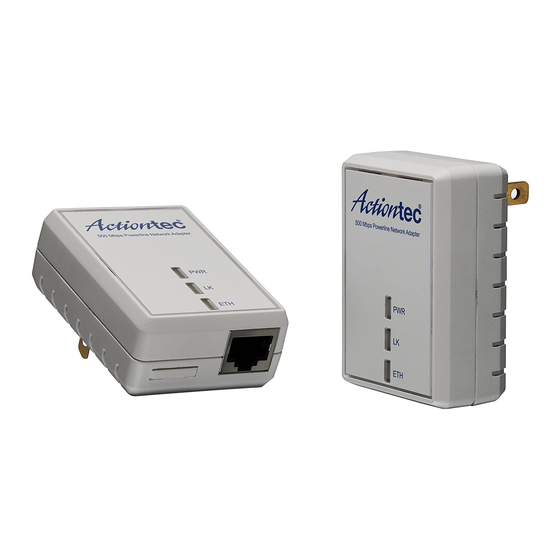
Power Light PLC Link Light Ethernet Link Light Status Lights Power On: This HomePlug Ethernet Bridge is receiving electrical power Off: Power off Flashing Green ( 1 second ON, 4 second OFF ) : Device in standby mode PLC Link The PLC (Powerline) Link light will indicate the overall speed of your network with 3 colors: Red: Minimum connection indicates weak signal and slower network speed: less than 5Mbps Orange: Normal signal with standard network speed: 5-39Mbps... -
Page 6: Initial Setup
This function is used to clear ALL data and restore ALL settings to the factory default values. Note: PWR500 must be plugged in to restore it to factory defaults. Hold the Reset button until the status lights begin to flash. -
Page 7: Adding Bridge C To Existing Network Ab (Network Abc)
The procedure is as follows: 1. Press and hold the Security button on Bridge A for no more than 10 seconds. Must release after 10 seconds. Once released, the Power light will flash. The password to Bridge A has just been erased and random security key has been generated. It must now be linked to your network to adopt the new network security key. -
Page 8: Removing Bridge B From Bridge A & C Network And Join With Bridge D & E (Network Bde)
The procedure is as follows: 8. Press and hold the Security button on Bridge C for no more than 10 seconds. Must release after 10 seconds. Once released, the Power light will flash. The password to Bridge C has just been erased and random security key has been generated. It must now be linked to your network to adopt the new network security key. -
Page 9: Troubleshooting And Disclaimer
Certain florescent or incandescent lights are noise sources on the electrical and can degrade performance. If your building has more than one circuit breaker box, your PWR500 PLC Adapter may not be able to connect between the different circuit breaker boxes. In this case, connect one HomePlug AV Ethernet Bridge to a power outlet located on each of the circuit boxes. - Page 10 Computer Interface IEEE802.3 ; IEEE802.3u Data PHY Rate Up to 500 Mbps Standards HomePlug AV Network Interface One RJ-45 (10/100Base-T Ethernet) One 500Mbps Power Line Port supporting co-existence with HomePlug 1.0 (14/85Mbps) Security 128-bit AES Link Encryption with Key Management Frequency Band 2-50 Mhz Modulation Schemes...
Need help?
Do you have a question about the PWR500 and is the answer not in the manual?
Questions and answers