Table of Contents
Advertisement
Quick Links
Signal
Master
-3
LD-1A Line Driver
-6
-9
-12
+ -
15V
Power
Mid-Hi
-3
-6
-9
-12
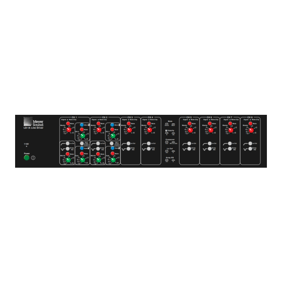
LD-1A Front Panel
Channel 1
PUSH
Input
Mid-Hi Out
DS-2 Out
PUSH
Channel 2
LD-1A Rear Panel
LD-1A
Line Driver
Patents Pending
CH 1
CH 2
Mute-Clip
Signal
Mute-Clip
Signal
Mute
Mute
φ
φ
DS-2
DS-2
Master
Master
0
0
-3
+3
+3
-6
Mute
Mute
DS-2
-9
DS-2
0
0
+6
+6
-3
-12
-3
+3
+3
-6
-6
-9
-9
+6
+6
-12
-12
DS-2
DS-2
Lo Cut
Lo Cut
& Sub
& Sub
Crossover
Crossover
φ
φ
Array
Array
Sub
Sub
EQ
EQ
Mute
Mute
Mute
Mute
Sub
0
Sub
0
0
Mid-Hi
0
-3
-3
+3
-3
+3
+3
+3
-6
-6
-6
-9
-9
-9
+6
+6
+6
+6
-12
-12
-12
Sub Out
Loop
Meyer Sound Laboratories, Inc.
Part #: 05.037.002.01 Rev B2
Operating Instructions
CH 3
CH 4
Mute-Clip
Signal
Mute-Clip
Mute
Mute
Mute
Master
Active
Mute
0
0
-3
-3
+3
+3
-6
-6
φ
Polarity
-9
-9
+6
+6
-12
-12
0
180
Crossover
Lo Cut
Lo Cut
Sub
DS-2 & Sub
Array
Array
Lo Cut
EQ
EQ
Out
In
Array EQ
Out
In
Channel 3
Channel 5
PUSH
PUSH
Input
Output
Input
Output
PUSH
PUSH
Channel 4
Channel 6
Copyright © 1997
All rights reserved
CH 5
CH 6
CH 7
Signal
Mute-Clip
Signal
Mute-Clip
Signal
Mute-Clip
Mute
Mute
Mute
Master
Master
Master
0
0
0
-3
-3
-3
+3
+3
+3
-6
-6
-6
-9
-9
-9
+6
+6
+6
-12
-12
-12
Lo Cut
Lo Cut
Lo Cut
Array
Array
Array
EQ
EQ
EQ
Channel 7
PUSH
CAUTION:
T250mA - 250V FUSE
Input
Output
PUSH
90-125/180-250 V
50-60 Hz 25W MAX
Channel 8
CH 8
Signal
Mute-Clip
Mute
Master
0
-3
+3
-6
-9
+6
-12
Lo Cut
Array
EQ
CAUTION:
Set voltage before
applying power.
AC Voltage Ranges
~
180-250V
~
90-125V
RISK OF FIRE REPLACE WITH
~
Advertisement
Table of Contents

Subscribe to Our Youtube Channel
Related Manuals for Meyer Sound LD-1A


Summary of Contents for Meyer Sound LD-1A
-
Page 1: Operating Instructions
Mute φ φ DS-2 DS-2 Master Master Master Master Active Mute Master Master Master Master LD-1A Line Driver φ Mute Mute Polarity DS-2 DS-2 Crossover DS-2 DS-2 Lo Cut Lo Cut Lo Cut Lo Cut DS-2 & Sub Lo Cut... -
Page 2: Symbols Used
6 sides Berkeley, California USA Vibration: 10 ñ 55 Hz (0.010 m April 1, 1997 peak-to-peak excursion) Made by Meyer Sound Laboratories Berkeley, California USA U U L L U U L L LISTED European Office: 3K59 ®... -
Page 3: Table Of Contents
Contents LD-1A Signal Flow Diagram........ 3 Auxiliary Channels 3-8 ..........6 Introduction ............4 Example Configurations .......... 7 Audio Input ............4 Safety Summary ............. 9 AC Power ............. 4 Specifications ............10 Main Channels 1 and 2 ........5... -
Page 4: Introduction
• provides gain, mute, and optimized EQ controls for six auxiliary systems; The LD-1A is balanced in and out, and consequently has no hot (+) pin. Pins 2 and 3 carry the input as a differential • maintains signal integrity for long cable paths. -
Page 5: Ac Power
φ φ DS-2 DS-2 Master Master The LD-1A operates in two AC voltage ranges: 90 – 125 V Mute Mute and 180 – 250 V, at 50 or 60 Hz. The voltage select switch DS-2 DS-2 on the rear panel must be set to the proper voltage before applying AC power. -
Page 6: Auxiliary Channels 3-8
Mid-Hi Output Auxiliary Channels 3-8 The Mid-Hi output has two switch-activated, optimized filters. Pushing the Lo Cut switch in activates a high- pass filter (160 Hz, Q = 0.8, –12 dB/octave) that performs The six auxiliary channels 3–8 control down-fill, front- a crossover function for the Mid-Hi output. -
Page 7: Example Configurations
• measure and equalize variations in frequency response caused by the acoustical environment and the placement and interaction of speakers. Contact Meyer Sound for assistance with your application. 650-P MSL-4 and PSW-2 Set the 650-P to the opposite polarity to the DS-2P and The MSL-4 and PSW-2 form a compatible full-range MSL-4. - Page 8 MSL-4, DS-2P, 650-P with CQ Down-fill This example shows the LD-1A integrating a complete system of self-powered speakers for a large venue. The diagram shows half of the system using channels 1, 3, and 5;...
-
Page 9: Safety Summary
Safety Summary English Français • To reduce the risk of electric shock, disconnect the LD-1A • Pour réduire le risque d’électrocution, débranchez la prise from the AC mains before installing audio cable. Reconnect principale de l’haut-parleur, avant d’installer le câble the power cord only after making all signal connections. -
Page 10: Specifications
Specifications Architecture Main (Channels 1, 2) Master Gain Control -12 to +6 dB Mid-Hi, DS-2, Sub Gain Controls -12 to +6 dB Low-cut Filter for Mid-Hi Output 160 Hz high-pass, -12 dB/octave, Q = 0.8 Array EQ Filter for Mid-Hi Output 6 dB cut at 220 Hz, 0.6 octave bandwidth Mute Mute switches for Master, Mid-Hi, DS-2, and Sub outputs...
Need help?
Do you have a question about the LD-1A and is the answer not in the manual?
Questions and answers