
Subscribe to Our Youtube Channel
Related Manuals for Sencore ASM 988A

Summary of Contents for Sencore ASM 988A
- Page 1 ASM 988A USER’S MANUAL 3200 Sencore Drive, Sioux Falls, SD. 57107 1-800-SENCORE Form 7270...
- Page 2 Support and Service information: Your ASM 988A is a delicate piece of equipment and needs to be serviced and repaired by SENCORE. For support and service information please address all your calls or mail SENCORE Inc. 3200 Sencore Drive Sioux Falls, S.D.
-
Page 3: Table Of Contents
TABLE OF CONTENTS UNIT DESCRIPTION ......................1 FEATURES ................. 1 User Interface and Remote Control..........1 Configurable Parameters ............1 Monitored Parameters............. 1 FRONT PANEL LAYOUT ..............2 BACK PANEL LAYOUT..............2 SPECIFICATIONS ..............3 8PSK Modulation Parameters ............3 QPSK Modulation Parameters ............3 ADVANCED QPSK Modulation Parameters .......... -
Page 4: Unit Description
ASM 988A – Manual UNIT DESCRIPTION The ASM 988A is a satellite modulator. This unit uses an advanced coding in the FEC layer to operate near Shannon’s theoretical limit of bandwidth efficiency. This unit accepts a M2P, DVB-SPI, DVB-ASI input transport stream and produces up to a 30 Mbaud modulated signal agile about 70 MHz. -
Page 5: Front Panel Layout
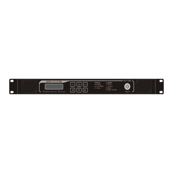
ASM 988A – Manual FRONT PANEL LAYOUT 1. Fan Intake with Removable Filter 2. Vacuum-Fluorescent Display (2 lines x 18 characters) 3. Keypad 4. Status LEDs 5. Alarm LEDs Ω 6. Modulator Test Output –20 dB Attenuated Signal Strength (75... -
Page 6: Specifications
ASM 988A – Manual SPECIFICATIONS 8PSK Modulation Parameters FEC rate FEC 2/3 FEC ¾-I FEC ¾-II FEC 5/6 FEC 8/9 Bit rate in 0.52 to 57.1 0.55 to 62.8 0.5 to 61.2 .59 to 68.5 0.61 to 71.4 Mbits/s Baud rate in 0.256 to 30... -
Page 7: If Output Specifications
• Dimensions: 19” W x 19” D x 1.75” H (1U rack mount chassis) Warning: Changes or modifications to this unit not expressly approved by SENCORE could void the user’s authority to operate the equipment. Note: This equipment has been tested and found to comply with the limits for a Class A digital device, pursuant to Part 15 of the FCC Rules. -
Page 8: Unit Quick Setup
UNIT QUICK SETUP Unpacking and Installation Each ASM 988A is packed with a AC Power Cord and is ready to be mounted into a 19” rack. The input data stream, IF output, and alarm output can be connected through the back panel. -
Page 9: Unit Operation
UNIT OPERATION Turning the Unit On The ASM 988A has a power switch located on the back panel near the AC power cord connector. Power to the unit should be turned on or off through the use of this switch. -
Page 10: Input Source
ASM 988A – Manual -IF Output Muted -Delete Sync Byte -System Parameters -Fault Settings -View Faults -Reset System -SNMP Settings INPUT SOURCE The input menu allows the input to the modulator to be switched between one of seven (7) possible modes, PN-23 Normal, Inv PN-23, M2P Sink Clock, M2P source clock, DVB-SPI and DVB-ASI, ASI Sink Clock. -
Page 11: M2P Sink Clock
This is the M2P parallel interface. See pin out in Appendix of this manual. The maximum input data rate on this interface for the ASM 988A is 85Mbits. In this mode the clock is sourced from the modulator. The modulator provides the byte clock that the source needs to use to provide the correct Transport Stream rate to the modulator. -
Page 12: Modulation Format
MODULATION FORMAT The Modulation Format menus allow changes to different modulation modes supported by the ASM 988A. When this menu is selected, several options can be viewed by using the Up/Down arrow keys to scroll through the settings. The Modulation menu allows DVB QPSK, 8-PSK mode, Advanced QPSK, Adv 16- QAM and DSS QPSK modes. -
Page 13: Output Level
ASM 988A – Manual Coding Rate. Changes to this value will affect the Symbol Rate. To change the Payload Rate, press ENTER to edit, using the Left/Right arrow keys select digits to modify and Up/Down arrow keys to change the digit value, and press ENTER to save. Note that in... -
Page 14: If Output Muted
ASM 988A – Manual IF OUTPUT MUTED The Modulator Output mode allows the output of the modulator to be either enabled or disabled. When set to disabled, the modulator will suppress the output to below –60 dBm. When enabled, the output of the modulator will be either the selected modulation mode or CW Test mode, if enabled. -
Page 15: Display Of System Information
ASM 988A – Manual Display of system information The ASM 988A display some information about the status of the unit as well as the settings. Use the up/down arrows to select to read the status of the unit. The following information are available through this menu. -
Page 16: Fault Settings
Fault Log, and, if activated, a relay alarm will trip. The ASM 988A monitors the following conditions: -Temperature: Above or below the normal internal operating temperatures: 0-50C -Voltages: Internal 5V, 3.3V, 1.8V, +12V, -12V 10% above or below nominal values. -
Page 17: Relay 2 Settings
ASM 988A – Manual To enable a faulty condition to trigger the relay, press ENTER and select enable with the up/down arrows. Note: No matter what the individual error conditions settings, the trigger cannot be triggered until the Master is enabled. -
Page 18: Snmp (Simple Network Management Protocol)
ASM 988A – Manual SNMP (SIMPLE NETWORK MANAGEMENT PROTOCOL) Simple Network Management Protocol (SNMP) is a protocol layer which is used with Ethernet to provide reliable system management from a remote location. On the ASM 988A, SNMP can be used to control and monitor the unit through both the Ethernet and serial ports. -
Page 19: Led Indicators
ASM 988A – Manual LED INDICATORS There are seven LED indicators on the unit, three status indicators and four alarm indicators. The three status indicators are to signal Power, Test and Local modes. Status Indicators (3) The Power indicator denotes that the unit is on. -
Page 20: Unit Maintenance
ASM 988A – Manual UNIT MAINTENANCE SERVICING THE UNIT There are no serviceable parts within the ASM 988A unit. Please return the unit to the factory for maintenance and repair. Sencore Electronics 3200 Sencore Drive Sioux Falls, South Dakota 57107... -
Page 21: Appendix A: Cable Pinouts
ASM 988A – Manual APPENDIX A: CABLE PINOUTS M2P Transport Stream Input Port Pin Number Connection CLOCK OUT + CLOCK IN + INPUT SYNC + INPUT DATA VALID + INPUT D0 + INPUT D1 + INPUT D2 + INPUT D3 +... -
Page 22: Dvb-Spi Transport Stream Input Port
ASM 988A – Manual DVB-SPI Transport Stream Input Port Pin Number Connection LCLOCK GROUND LVALID LPSYNC GROUND /LCLOCK GROUND /LD7 /LD6 /LD5 /LD4 /LD3 /LD2 /LD1 /LD0 /LVALID /LPSYNC... -
Page 23: Alarm Relay Output Port
ASM 988A – Manual Alarm Relay Output Port Pin Number Connection Relay 2 – Normally Open Relay 2 – Common Relay 1 – Normally Closed Relay 1 – Normally Open Relay 1 – Common Relay 3 – Normally Closed Relay 3 – Normally Open Relay 3 –... -
Page 24: Appendix B: Software Tree
ASM 988A – Manual APPENDIX B: SOFTWARE TREE Table 1 illustrates the menu tree accessible through the front panel. This table is structured from left to right, where menus to further to the right are submenus. Root Submenu Submenu Submenu... - Page 25 ASM 988A – Manual NOTES:...
Need help?
Do you have a question about the ASM 988A and is the answer not in the manual?
Questions and answers