
Related Manuals for Trio ER450

Summary of Contents for Trio ER450
- Page 1 E Series Data Radio – User Manual User Manual E Series Data Radio ER450 Remote Data Radio EB450 Base Station EH450 Hot Standby Base Station www.trio.com.au Issue 7: May 2005 © Copyright 2005 Trio DataCom Pty. Ltd. Page 1...
-
Page 2: Table Of Contents
Examples of Predictive Path Modelling Data Connectivity Power Supply and Environmental Considerations Physical Dimensions - Remote Data Radio - ER450 Physical Dimensions - Base Station - EB450 Physical Dimensions - Hot Standby Base Station - EH450 Part E – Getting Started... - Page 3 Part B - E Series Overview Part C - Applications Part D - System Planning and Design Part E - Getting Started Part F - Operational Features Part G - Commissioning Part H - Maintenance © Copyright 2005 Trio DataCom Pty. Ltd. Page 3...
-
Page 4: Part A - Preface
Compliance Information equipment for repair under warranty must be returned freight paid to Trio DataCom Pty Ltd or to such other place as Trio DataCom FCC Notice (Hot Standby Controller Only) Pty Ltd shall nominate. Following repair or replacement the equipment shall be returned to the customer freight forward. -
Page 5: Related Products
Class I, Division 2. Refer to Articles 500 through 502 of the National Electrical Code (NFPA 70) and Section 18 of CSA C22.1 for further information on hazardous locations and approved Division 2 wiring methods. © Copyright 2005 Trio DataCom Pty. Ltd. Page 5... -
Page 6: Part B - E Series Overview
Unique integrated C/DSMA collision avoidance technology permits simultaneous polling and spontaneous reporting operation in the same system. • Digital receiver frequency tracking for long term data reliability. EH450 Hot Standby Base Station Page 6 © Copyright 2005 Trio DataCom Pty. Ltd. - Page 7 • Digital plug in order wire option for commissioning and occasional voice communications without the need to inhibit users application data. Features and Benefits of ER450 Remote Data Radio • Optional full duplex capable remote – separate Tx and Rx ports for connection to an external duplexer.
-
Page 8: Model Number Codes
= Diagnostics - [DIAGS/D, DIAGS/DH, DIAGS/E or DIAGS/EH, DIAGS/M] (D, E & M Series Only) = Full Duplex Operation [ERFD450] (ER450 only) = Full Duplex Operation and Diagnostics [ERFD450 & DIAGS/E] (ER450 only) = SMA Connector (SR450 Remote Only) RF Channel Data Rate & Bandwidth (Internal Modem ) -
Page 9: Standard Accessories
(N Type – Tx Port, SMA - Type Rx Port) Note: Requires external duplexer Frequencies must be specified at time of order. ERFDTRAY 19” Rack Tray for Mounting of ER450 Full Power Supplies Duplex Radio and External Band Reject Duplexer PS13V82A Power Supply 13.8V 2A 240VAC... -
Page 10: Part C - Applications
(such as powerline ACRs). In addition, other applications such as meteorological stations etc. area wide security and alarm systems, public information systems (traffic flow and public signage systems) and environmental monitoring systems. Page 10 © Copyright 2005 Trio DataCom Pty. Ltd. -
Page 11: Systems Architecture
“transparently”, allowing the application’s protocol to provide the addressing, and thus control the traffic. Where the application layer does not provide the addressing, the E Series can provide it using SID codes™. © Copyright 2005 Trio DataCom Pty. Ltd. Page 11... - Page 12 RF point of view, and the application master is effectively a “remote” from an RF point of view, even though it is controlling the Digipeater System Backbone Store and Forward System Page 12 © Copyright 2005 Trio DataCom Pty. Ltd.
-
Page 13: Part D - System Planning And Design
field strength testing. It is good design practice to consider the results of at least two of these models to design a radio path. © Copyright 2005 Trio DataCom Pty. Ltd. Page 13... -
Page 14: Examples Of Predictive Path Modelling
Radio path with good signal levels, attenuated only by free space loss. Obstructed Radio Path This path has an obstruction that will seriously degrade the signal arriving at the field site. Page 14 © Copyright 2005 Trio DataCom Pty. Ltd. - Page 15 Part D – System Planning and Design Effect of Earth Curvature on Long Paths This path requires greater mast height to offset the earth curvature experienced at such a distance (73km). © Copyright 2005 Trio DataCom Pty. Ltd. Page 15...
-
Page 16: Antenna Placement
When aligning a directional antenna, avoid placing your hands or body in the vicinity of the radiating element or the forward beam pattern, as this will affect the performance of the antenna. Page 16 © Copyright 2005 Trio DataCom Pty. Ltd. -
Page 17: Data Connectivity
DTE (terminal) – loop RTS to CTS, and DTR to DSR and DCE. DCE (modem) - loop DSR to DTR and RTS (note-not required for E Series modem when set for no handshaking). © Copyright 2005 Trio DataCom Pty. Ltd. Page 17... - Page 18 E Series Data Radio – User Manual Part D – System Planning and Design Cable Wiring Diagrams Page 18 © Copyright 2005 Trio DataCom Pty. Ltd.
- Page 19 E Series Data Radio – User Manual Part D – System Planning and Design Cable Wiring Diagrams RS232 Connector Pin outs (DCE) Port A and B, Female DB9 © Copyright 2005 Trio DataCom Pty. Ltd. Page 19...
-
Page 20: Power Supply And Environmental Considerations
- Specifications for more details of the power supply requirements. Caution: There is NO readily serviceable internal fuse, and therefore the radio modem MUST be externally fused with a fuse and fuse holder (ER450: 3 amp fast-blow fuse, EB450: 5 amp fast-blow fuse). Page 20... -
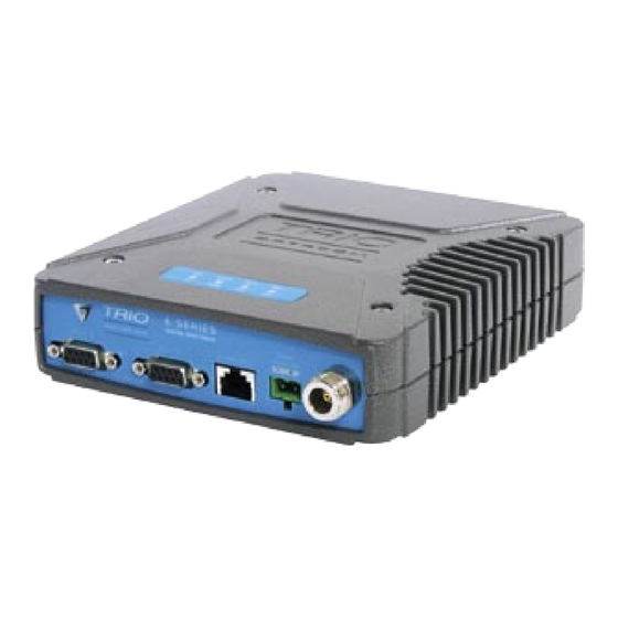
Page 21: Physical Dimensions - Remote Data Radio - Er450
E Series Data Radio – User Manual Part D – System Planning and Design Physical Dimensions - Remote Data Radio - ER450 © Copyright 2005 Trio DataCom Pty. Ltd. Page 21... -
Page 22: Physical Dimensions - Base Station - Eb450
E Series Data Radio – User Manual Part D – System Planning and Design Physical Dimensions - Base Station - EB450 Page 22 © Copyright 2005 Trio DataCom Pty. Ltd. -
Page 23: Physical Dimensions - Hot Standby Base Station - Eh450
E Series Data Radio – User Manual Part D – System Planning and Design Physical Dimensions - Hot Standby Base Station - EH450 © Copyright 2005 Trio DataCom Pty. Ltd. Page 23... -
Page 24: Part E - Getting Started
Mounting and Environmental Considerations Introduction The ER450 radio comes complete with a mounting cradle and is attached to a panel or tray by means of screws or bolts, using the Welcome to the ER450 Quick Start Guide. This guide provides hole slots provided. - Page 25 E Series Data Radio – User Manual Part E – Getting Started - ER450 ER450 Connections Layout The TVIEW+ Cable is a standard CAT 5 RJ-45 (Male) to RJ-45 (Male) patch cable. It is intented for RS232 serial communications only and should not be connected directly into an ethernet port of a PC.
- Page 26 E Series Data Radio – User Manual Part E – Getting Started - ER450 User Interfaces – Ports A & B RS232 Connector Pin outs (DCE) Port A and B, Female DB9 Each user port (A & B) is wired as a RS232 DCE, configurable for no handshaking (3-wire) interface, or for hardware or software (X- on/X-off) flow control.
-
Page 27: Part I - Tview+ Management Suite
The configuration wizard can be used to provide Quick Start and therefore the radio modem MUST be externally fused generic templates for the types of systems architecture you wish with a fuse and fuse holder (ER450: 3 amp fast-blow fuse, to employ. EB450: 5 amp fast-blow fuse). - Page 28 E Series Data Radio – User Manual Part E – Getting Started- ER450 Optimising the Antenna for best RX LED Indicators & Test Outputs signal LED Legend Once the unit is operational, it is important to optimise the antenna tuning.
- Page 29 E Series Data Radio – User Manual Part E – Getting Started- ER450 Verifying Operational Health Received Signal Indicator It is possible to verify the operation of the radio modem using the LED Legend indicators provided by the unit. The state of the transmitter and receiver, and data flow can be interpreted by the indicator LEDs...
-
Page 30: Eb450 Quick Start Guide
Communications Ports All permanent connections are made at the rear of the unit. This See ER450 Quick Start Guide Section includes: Power, Antenna, Communications Ports, Digital I/O and System Port. The front panel has an additional System Port Power Supply and Protection connection point for easy access.
Need help?
Do you have a question about the ER450 and is the answer not in the manual?
Questions and answers