Table of Contents
Advertisement
Quick Links
Advertisement
Table of Contents

Related Manuals for Inverto 5415 IDLU-SPAL03-OOOBT-OPP

Summary of Contents for Inverto 5415 IDLU-SPAL03-OOOBT-OPP
- Page 1 SatPal Controller 5415 IDLU-SPAL03-OOOBT-OPP Item: 5415 Quick Guide...
-
Page 3: Table Of Contents
CONTENTS English Notices ............................4 Quick User Guide ..........................6 Install the application ........................6 SatPal™ Controller ..........................6 Connect the SatPal Controller ......................8 Start the application .........................8 Connect the application with the SatPal™ Controller ...............8 Home screen ............................9 Sat meter ............................10 Setup of LNB for Sat meter ......................10 Sat meter signal meters ........................11 Sat meter Options ..........................11 Sat meter Spectrum ........................12... -
Page 4: Notices
NOTICES Copyright No part of this manual may be copied, reproduced, used or translated in part or whole without Communication Technologies S.à.r.l (hereinafter “FTA”) prior consent in writing. CE Declaration of Conformity Hereby,FTA Communication Technologies S.à.r.l declares that the SatPal™ Controller is in compliance with the essential requirements of Directives 2014/30/EU (EMC), 2014/35/EU (LVD), Eco-Design Directive (2009/125/EC), Radio Equipment Directive (2014/53/EU) and Radio and Telecommunication Terminal Equipment (R&TTE 1999/5/EG). - Page 5 Please retain the original packaging, should it be necessary at some stage to return the unit. Product support For any further product support and inquiries, please contact us at any of the following options: FTA Communication Technologies S.à.r.l 18 Duchscherstrooss Wecker 6868 Luxembourg Tel.: +352 264 367 1 Fax: +352 264313 68 Mail: info@inverto.tv www.inverto.tv...
-
Page 6: Quick User Guide
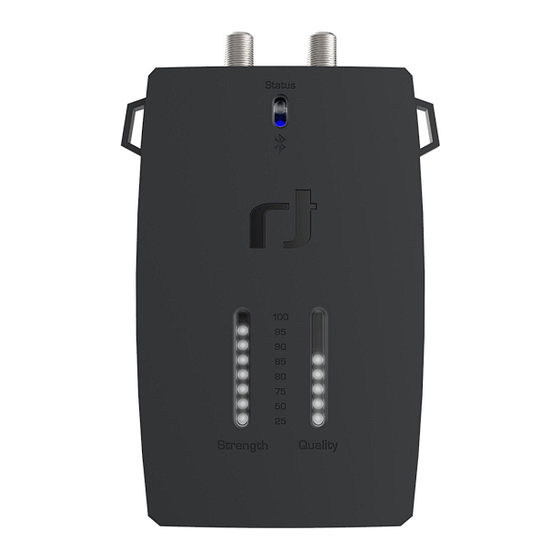
Download and install the application on your smartphone from the Apple iTunes store or android Google Play Store by searching for SatPal™ from Inverto Digital Labs. Note: Layouts and usage of the SatPal™ application are slightly different between iOS and android OS, moreover appearance depend on your screen size. - Page 7 1. LNB/Switch (DC Out) – F-type Connect to the LNB/ Multiswitch to be setup/programmed. 2. Receiver (DC IN, RF Loop) – F-type RF signal loop-through and power supply (10-20V/13W max.) from receiver or power inserter. 3. Status LED Blinking yellow: communication with LNB/Multiswitch. Steady green: configuration of connected dCSS device is same as configuration stored in SatPal Controller (standalone mode).
-
Page 8: Connect The Satpal Tm Controller
Connect the SatPal Start the application Controller After installation start the application by tapping Connect the SatPal Controller to power (e.g. to on the application icon as shown in Figure 5 app a portable power bank or AC/DC adapter). Icon. A portable power bank can be fixed with a rubber ring at the back of the SatPal™... -
Page 9: Home Screen
!Attention! Connecting over Bluetooth is only If you tap on the menu icon as shown in Figure 8 Menu , a list with all available options will be possible via the application and not from the ge- shown as in Figure 9 Home menu. neric iOS/Android Bluetooth settings. -
Page 10: Sat Meter
Sat meter Setup of LNB for Sat meter Home » Sat meter » LNB Configuration Home » Sat meter Tap on “LNB Configuration” to select the right The Sat meter function allows to measure satel- type and set the parameters of your connected lite signals and to optimize the reception quality if LNB device. -
Page 11: Sat Meter Signal Meters
Sat meter signal meters Sat meter Options Home » Sat meter » ‘signal bars’ Home » Sat meter » ‘signal bars’ » Options Tapping on the “signal bars” at Figure 10 Sat Tap on “Options” as shown in Figure 12 meter menu will display detailed signal meters Signal meter to change parameters for the as seen on Figure 12 Signal meter. -
Page 12: Sat Meter Spectrum
Sat meter Spectrum Install & Report Home » Sat meter » ‘signal bars’ » Spectrum Home » Install & report Tap on “Spectrum” at screen Figure 12 Signal The Install & Report function allows you to record meter to see the spectrum of the selected tran- the signal quality of your installation and generate sponder. - Page 13 Tap on “+” to add a new equipment item. Figure Type in your location data like “Location name”, 17 New equipment will appear. “Street / House no.” and “City” to be shown in the site installation report. Tap on the respective field to insert your data. Swipe again the screen to the left and you will see the input screen for the “Equipment list”...
- Page 14 If you have an Inverto LNB or Multiswitch device Tap “Select” at the bottom to select the data and tap on “+” for Model. Screen Figure 18 New to go one screen backwards. See Figure 19 After equipment Items# appears.
- Page 15 Then tap on “Save” to save the equipment infor- If you want to delete an item just slide the bar mation. Figure 20 Equipment list with items of the respective item to the right and tap on “Remove”. See Figure 21 Remove Equipment shows an example with two items.
- Page 16 Swipe again the screen to the left, see Figure 23 Swipe again the screen to the left for the “Photo documentation” and take one or more pictures Installation summary. by tapping on “Take Photo”, see Figure 22 Photo documentation. Figure 23 Installation summary You can check again the “Signal Quality”...
- Page 17 Tap on “Send” to send the report. Screen as shown in Figure 24 Send Installation Report will be shown. Figure 24 Send Installation Report The report will be sent to the email address set at ‘target e-mail’ under the section Settings (“Home »...
- Page 18 The report, in PDF format, will be attached and includes all prior inserted data. As example see an excerpt at Figure 25 Installation Report of a generated installation report. Installation Report Sent: 2017-04-18 At: 10:14 Installer Name: Martin e-mail: Martin.Muster@muster.sat Mobile: 00352123456789 ID: 758C5840-CD17-4A43-9E38-B7808E4DC24F TP Signal Parameters...
-
Page 19: Report History
Report History By tapping on “Purge History” at the bottom you Home » Report History can purge all sent reports. A window to confirm will pop up prior deletion. At this section you will find a list of sent reports stamped with date, time and location. -
Page 20: Unicable Ii Configuration
Unicable II Configuration Home » Unicable II Configuration Unicable II configuration with Home » Unicable II Configuration » upper rectangle At this section you can read and edit the configuration of connected Unicable II LNB or MSW devices. Scope and possible changes depend on connected device. - Page 21 Tap on “Configuration” to read the configuration Tap on “Mode” to change the operating mode of of the connected device. the LNB. For an Unicable II LNB either “Dynamic” or “Static” mode. See Figure 31 Mode LNB. The configuration data will be displayed on the screen as at Figure 30 Configuration, LNB.
- Page 22 Tap on a particular UB row below the section To disable a user band swipe the row of the re- “Output” to change the particular UB configura- quired UB to the right and tap on “Disable”, see tion. See Figure 32 Configuration User Band, Figure 33 Disable, Enable UB.
-
Page 23: Unicable Ii Configuration With Multiswitch
Unicable II Configuration with A screen as shown at Figure 35 Unicable II Con- Multiswitch nected Device, MSW will be displayed. Home » Unicable II Configuration When an Unicable II Multiswitch is connected to the SatPal™ Controller, the screen at Figure 34 Unicable II Configuration, MSW will be displayed. - Page 24 When reading the configuration data is com- Tap on a particular UB row in order to edit the set- pleted, a screen as at Figure 36 Configuration, tings of that UB. See Figure 37 Configuration MSW will be displayed. User Band, MSW. Figure 36 Configuration, MSW Figure 37 Configuration User Band, MSW On this screen, you can set the type of LNB that...
-
Page 25: Unicable Ii Configuration Diagnostic
Unicable II Configuration To disable a user band swipe the row of the re- Diagnostic quired UB to the right and tap on “Disable”, see Home » Unicable II Configuration » ‘upper Figure 38 Disable, Enable UB, MSW. rectangle’ » Diagnostic After tapping on “Unicable II Configuration”... -
Page 26: Unicable Ii Configuration Diagnostic Spectrum
Unicable II Configuration To change the capture parameters tap on Diagnostic Spectrum “Change” at Spectrum display. You will see Home » Unicable II Configuration » ‘upper changeable parameters as shown at Figure 41 rectangle’ » Diagnostic » Spectrum Spectrum Capture Parameter. Tap on “Spectrum”... -
Page 27: Unicable Ii Configuration Diagnostic Usage Information
Unicable II Configuration In case of no device is connected and you tap on Diagnostic Usage Information “Home » Unicable II Configuration »” screen as Home » Unicable II Configuration » ‘upper shown at Figure 42 Unicable II Configuration rectangle’ » Diagnostic » Usage Information Editor will be displayed. - Page 28 At this screen you can chose the Unicable II de- vice for which a configuration should be gener- ated and later maybe modified. Scroll the wheel under “Device:” until the desired 4 digit inverto item number is displayed. Under field “File Name:” type in a filename. As hint: A filename should always include Inverto’s...
- Page 29 Further details about configuration files and pos- To upload the configuration file to the device sible modifications on Page 30: Configuration (ODU) tap on “Upload to ODU”. Editor examples with MSW. To upload the configuration file to the SatPal™ If you want to delete a configuration file swipe Controller tap on “Upload to SatPal Controller”.
-
Page 30: Configuration Editor Examples With Msw
Configuration Editor Settings examples with MSW Home » Settings Depending on the type of connected MSW de- At this section you can see connected SatPal™ vice, the configuration options will be displayed. Controller, enter personal details of the installer, set the e-mail address where to send the instal- !Attention! Creating/editing a product configu- lation reports to, to link with a Dropbox account. -
Page 31: Satpal™ Controller
SatPal™ Controller Tap on “Settings” to enter the setting section. See Figure 48 Setting section. Home » SatPal Controller At this section you can trigger a firmware upgrade of the SatPal™ Controller, to set a TP Configura- tion for standalone mode, to define the function of the “User button”... -
Page 32: Firmware Upgrade
Firmware upgrade TP Configuration Home » SatPal Controller » TP Configuration Home » SatPal Controller » Firmware upgrade At this section you can configure four TP’s for the Tap on “Firmware upgrade” at “Home » Control- toggling mode while the SatPal™ Controller is ler”... - Page 33 For instance, to setup a configuration for TP1, LNB Type: tap on the “row of TP1”. A screen as shown at You can choose between dCSS Dynamic or Figure 51 TP Configuration TP1 will be dis- Universal. If you choose Universal you can assign played.
-
Page 34: User Button Function
Tap on “Select” to apply your selection. gle” or “Send Config” and then tap on “Send to SatPal Controller” at the bottom to upload the After all TP’s have been assigned and configured setting to the SatPal™ Controller. accordingly you have to tap on “Send to SatPal Controller”... -
Page 35: Specifications
SPECIFICATIONS Frequency range Satellite (LNB/Multiswitch and Receiver ports) 950-2150MHz Bluetooth 2.4GHz Interfaces LNB/Multiswitch 1x Satellite IF + 13/18VDC out + 0/22kHz, F-type Receiver 1x Satellite IF loop-through out + 13/18VDC in, F-type PC (Data) 1x PC data communication, micro USB Bleutooth (Wireless data) 1x Bluetooth low energy (IEEE 802.15.1 BT4.0) DC In... -
Page 36: Abbreviations
ABBREVIATIONS Bit Error Rate Carrier to Noise ratio dCSS Digital Channel Stacking System Intermediate Frequency Low Noise Block Converter Modulation Error Ratio Multiswitch Outdoor Unit: e.g. LNB, Multiswitch Set-Top-Box Transponder User Band... - Page 38 For purpose of brevity, some product descriptions in this sheet remain at platform level and may not be referred to as detailed datasheets of the products. Inverto Digital Labs reserves the right to amend, omit or add products, product-lines, and / or fea- tures without notice.
Need help?
Do you have a question about the 5415 IDLU-SPAL03-OOOBT-OPP and is the answer not in the manual?
Questions and answers