Table of Contents
Advertisement
Quick Links
Advertisement
Table of Contents

Related Manuals for Canberra Lynx

Summary of Contents for Canberra Lynx
- Page 1 Lynx™ Digital Signal Analyzer User’s Manual ICN 9240227E...
- Page 2 Copyright 2008, Canberra Industries, Inc. All rights reserved. The material in this document, including all information, pictures, graphics and text, is the property of Canberra Industries, Inc. and is protected by U.S. copyright laws and international copyright conventions. Canberra expressly grants the purchaser of this product the right to copy any material in this document for the purchaser’s own use,...
-
Page 3: Table Of Contents
Controls for the Lynx System ........ - Page 4 Lynx and MID Files ........
- Page 5 Communicating with Lynx........56...
- Page 6 Lynx Web-Enabled Access ........59...
- Page 7 MCA Settings ......... . . 77 Inputs .
- Page 8 Readings and Faults Table ....... . 139 Lynx™ Digital Signal Analyzer...
- Page 9 5. The Mixed Signal Oscilloscope ....140 Launching the Scope ........140 Display Options .
- Page 10 Communicating With Lynx ........157...
- Page 11 D. Rack-mounting Your Lynx ....193 Rack-mounting a Single Unit ........194 Rack-mounting Two Units .
- Page 12 For Your Notes Lynx™ Digital Signal Analyzer...
-
Page 13: Preface
All current spectroscopy detector types are supported by the built-in tri- ple-range dual-polarity HVPS. This User's Manual is intended for the readers who will use the Lynx in their facility to acquire spectroscopic data; the installer or technician who will initially set up the system with other measurement and network equipment;... - Page 14 For Your Notes Lynx™ Digital Signal Analyzer...
-
Page 15: Introduction
This manual describes the capabilities of the Lynx DSA and its Web-browser-based control software. Setup and interaction with the Genie 2000 software is reviewed, as it relates to the Lynx MCA. System setup details for the Lynx system are provided, and User instructions for data acquisitions is also described. -
Page 16: Navigating In This Manual
If not yet configured, enter user = administrator and password = password. • The Lynx Menu is to the far left. Under MCA Settings | Acq Setup, change any acquisition parameters as needed from the options offered. Press Submit to keep any changes made, or Reset to discard your changes here. - Page 17 Lynx. Figure 2 - Lynx web-based User Interface and display, typical The Lynx Menu steps are referenced along the top of the manual pages in Chapter 4 to help guide you through the details. 5. Using the Digital Oscilloscope This chapter discusses the Lynx’s built-in digital oscilloscope function.
-
Page 18: Key Features
Sample Changer control, plus general-purpose I/O connectors. • Flexible form factor: for Standalone Desktop use; or rack-mount – one Lynx unit, or two Lynx units side by side, may be rack-mounted in 2U of a standard 19 inch electronics cabinet using the optional rack-mount kit. -
Page 19: Acquisition Modes
Auxiliary Counters Auxiliary Counters are supported. If using the Lynx Programming Libraries, heed the Caution statements before Enabling Counters. See MCA Settings | Counters. Digital Storage Oscilloscope (DSO) Lynx incorporates a multi-trace digital and analog oscilloscope. -
Page 20: Faq & Common Events
Remember After making changes, press Submit to save your new data. Access the Lynx system You connect to the Lynx through another computer or terminal, and your site's access parameters will be unique. See the Quick Start, or review the Setup starting in Chap- ter 3 and the browser-based network User Interface starting in Chapter 4. - Page 21 FAQ & Common Events Set up the Spectrum's plot options See Spectrum | Display; or, in some browsers, the display controls are already open. Select an Input by Name: (centered, above the spectral display). Click the Options tab in the display controls. Set the plot options as desired; your changes are immediate. Rename an Input See MCA Settings | Inputs.
-
Page 22: Sample Energy Calibration
Energy Calibration using the browser-based interface is provided as an example be- low. This will help demonstrate how you will use the Lynx. This is an overview only; specific Lynx setup options and details are described in this manual, especially in Chapter 4 which discusses the Menu and options in detail. - Page 23 Sample Energy Calibration From the Lynx Menu, select Gain under MCA Settings. While observing the spectrum display, use the Coarse Gain and Fine Gain to adjust your desired peaks into the area or correct channels. This is also creating the required slope data for your energy calibration.
- Page 24 Figure 6 - Adding an ROI The Energy value for that peak is displayed across the top of the spectral display. See Figure 6 and look for the Chan: field, which in this example shows 663.7 keV. Lynx™ Digital Signal Analyzer...
- Page 25 Sample Energy Calibration 6b.) Now you want to set your marker, selecting the Region of Interest. Press the Select ROI button. Figure 7 - Selecting the ROI 6c.) Next, using the data from the acquisition, enter in the correct Energy value. Again, this was 663.7 keV from this example, as seen back in Figure 6.
- Page 26 Repeat Steps 6a) through 6d) until you have entered your data points. 6e.) The List of peak energies to be used in the Energy - Channel Entry list is now complete. Figure 10 - List of Energies Lynx™ Digital Signal Analyzer...
- Page 27 Sample Energy Calibration Compute using your Data Select the Compute button to calculate the Energy calibration and coefficients. Figure 11 - Energy Equation The Energy Equation plot appears as a result of your data input. Saving the Energy Equation and Coefficients Press the Submit button to save the configuration for the Input selected.
- Page 28 FWHM parameters must be entered manually, on the Energy Calibration Coefficients page. Figure 13 - Energy Calibration Coefficients The FWHM Shape (for this example) can be seen as shown in Figure 14. Figure 14 - FWHM Shape The calibration is complete at this point. Lynx™ Digital Signal Analyzer...
-
Page 29: Controls And Connectors
It is not absolutely necessary to be able to observe these indicators during operation, as the real-time results are displayed in the Lynx's user interface. However, before inter- acting with the connectors on the rear of the Lynx unit, you may wish to observe these status indicators for your own safety. -
Page 30: Led Status
• Steady Red – Signals a self-diagnostic error. The reason for the error can be confirmed through the appropriate control software (Genie 2000 or the web interface). A Diagnostic procedure is available if the Lynx interface is operational. • LED is Off – Instrument is not receiving power. -
Page 31: Rear Panel Connectors
Rear Panel Connectors Rear Panel Connectors The Rear Panel connectors (Figure 16) are summarized here. For each connector's technical data, refer to Appendix A, Specifications. Figure 16 - Rear Panel Connectors Inputs CHGR RDY Accepts Sample Changer Ready signals; polarity is software selectable. GATE –... -
Page 32: General Purpose I/O
GPIO3 is used to receive the Test Pulser signal (if enabled). Outputs CHGR ADV Sample Changer Advance output provides a pulse for each sample advance com- mand. Incoming Count Rate connector provides a positive output pulse for each incoming event above the instrument's threshold setting. Lynx™ Digital Signal Analyzer... -
Page 33: High Voltage Power Supply Outputs
Preamp cable. High Voltage Power Supply Outputs The Lynx provides a triple-ranged high voltage power supply (HVPS) for your detec- tors. Only one of the high voltage connectors is active at a time, depending on the user's settings, and status of their acquisition operations. -
Page 34: Lynx System Power
USB D Full speed USB Device connection of the Lynx to a host PC; this is a regular USB B-type receptacle. Use a USB A-to-B cable to connect Lynx to your PC. One such ca- ble is provided with the Lynx unit. -
Page 35: Controls For The Lynx System
Lynx. Applying Power To turn on the Lynx, plug the AC adapter's cordset into the adapter and to the mains (power). Connect the power lead into the Lynx' power jack marked 12 V 1.0 A. -
Page 36: Factory Reset Control
Chapter 2 - Controls and Connectors Factory Reset Control The factory reset button is located behind a small hole in the Lynx's bottom panel. CAUTION Operating this control will cause a loss of stored data, and will interrupt an acquisition in process. -
Page 37: System Setup
3. System Setup This chapter serves as an overview of setting up a basic Lynx™ system, the Lynx in- strument and its Web-enabled control software. Those user-based commands that are related to a one-time-only setup function, such as network connections and other sys- tem-affecting concerns are also introduced in this section. -
Page 38: Genie 2000 Analysis Software (Optional)
Lynx and MID Files Your Lynx' MCA information can be saved as a file or files that you can save and ex- change with the Genie 2000. You may recall that this 'file' is a MID file, and the Genie 2000 includes tools to create and modify MID files - specifically, the MID Wizard, and the MID Editor. -
Page 39: Editing The Definition
Genie 2000 Analysis Software (optional) The key piece of information here is the File Descriptor, which you added when the file was first saved. This should help you decide if the file you selected is the one you want to edit. Editing the Definition All of the menus and commands available for defining an MCA are also used for edit- ing a definition. -
Page 40: Mca Input Definition (Mid) Editor
MCA Input Definition (MID) Editor This section discusses using the MCA Input Definition (MID) Editor. The MID Edi- tor is optional, part of the Genie 2000 product, and not a part of the Lynx product. Note This shows examples of screens and entry names that you might see, not nec- essarily exact details for your configuration, which can vary. -
Page 41: Starting The Mid Editor
MCA Input Definition (MID) Editor We’ll discuss how to add (and delete) the MID editor’s MCA entries and will explain what the definition entry consists of, to build an MCA Definition list. Using the MCA Definition Files To use an MCA Definition, load that MID file into the VDM’s internal MCA Runtime Configuration Database. -
Page 42: Adding An Mca
Click ADD to add it to the MCA Input Definition Editor list. Click Done to return to the main MID window, which will close the Available MCA list. You can add more Lynx MCAs to the definition at any time using these steps. Lynx™ Digital Signal Analyzer... -
Page 43: Defining An Mca
Lynx controls or features. Figure 20 - MID definition for the Lynx MCA To begin, select the Lynx MCA entry in the Definition Table that you wish to set up. Device Setup The Devices menu sets the parameters for the Lynx’s MCA and associated devices. -
Page 44: Mca
Selecting the MCA command in the Devices menu pops up the Dialog Box shown be- low. You may identify this Device by entering in its IP Address (and press OK) Figure 21 - Identify Lynx Device by entering its IP Address or its exact DHCP Name (and press OK). - Page 45 Device Configuration Would be 'as necessary' in configuring your High Voltage, Sample changer, DSP Gain and DSP Filter shaping would all be utilizing the Lynx configuration settings via the MVC Adjust screens after editing the configuration and saving the MID file.
-
Page 46: Interpreting The Definition Entry
You can easily edit this assignment to an input name of your choice. Size This shows the number of data channels assigned to this input. Gain This column describes the DSP Gain device associated with the Lynx DSP. Lynx™ Digital Signal Analyzer... -
Page 47: Other Entries
You can use the Genie 2000 software to access a detector's configuration information by loading its MID file. You've just saved a MID file (above) for your Lynx configu- ration, so you can now use this MID configuration with the Genie 2000. - Page 48 Figure 27 - How to Load a MID file for use with Genie 2000 • The Load Definition window appears. Select the MCA definition file from the Files: window (in this example, DEMO-013 is for our Lynx's MCA). Figure 28 - Select your MCA's MID file for use with Genie 2000 •...
- Page 49 MCA Input Definition (MID) Editor 13. Opening Detector Datasource for Lynx configurations From within the MVC window in Genie 2000, select the Detector Datasource. Figure 29 - Using MVC Window to select a Detector Datasource Starting Genie Acquisition and Analysis Window (GAA) Figure 30 - Opening Gamma Acquisition program window User’s Manual...
- Page 50 Select the desired detector data source, and press Open. Figure 31 - MVC Window, select the Lynx Datasource The Lynx MCA is now opened in the MVC window. Settings can now be applied to High Voltage, Gain or many other facilities within the MVC window via the MCA Adjust pull down menu.
- Page 51 MCA Input Definition (MID) Editor 14. Utilizing the MCA Adjust pull down menu to adjust parameters. Now that the existing values from the datasource are loaded, you can make adjust- ments as needed. From the MCA heading, select the Adjust... command. Figure 33 - GAA, select MCA then select Adjust...
- Page 52 Figure 36 - MVC window, Adjust Gain settings By using the Coarse Gain and Fine Gain you can adjust the desired peaks to the de- sired energy-channel relationship by using the slide bars and lining up each peak ac- cordingly. Lynx™ Digital Signal Analyzer...
-
Page 53: Saving The Input Definition
Then, select the Filter radio button to edit the Filter settings. Figure 37 - MVC Window, Filter settings 17. Completion of the Definition and Setup of the Lynx DSA. Once the system has been setup and adjusted for HV, Amplifier Gain, or Filter adjust- ments made for the Rise and Flat-Top, typical calibrations would be performed on the system as any other MCA style system. -
Page 54: Using Mca Definition Tables
MCA Definition Files into the MCA Runtime Configuration Data- base. This database is shared by all of the programs which make up the Lynx software pack- age, and is used by those programs to gain access to the actual MCA hardware in your system. -
Page 55: Unloading The Database
Acquire Setup with Genie 2000 This section includes a 'review' of options presented in the Genie 2000 documentation. Only those options that are supported with your Lynx setup will be discussed here. Figure 38 - Acquisition Setup Controls in Genie 2000 The External Control options have been enhanced in Genie 2000 version 3.1a. -
Page 56: External Start/Stop
• Start Only, Stop Only, and Start and Stop allow an external signal pulse to change the state of an acquisition once; subsequent external signal inputs are ignored. • Suspend & Resume will toggle the state of the acquisition upon receipt of an external signal pulse. Lynx™ Digital Signal Analyzer... -
Page 57: Coincidence
Using MCA Definition Tables Start Only An External Start/Stop pulse starts acquisition. Acquisition is first armed by pressing the Start button. Then the signal level triggers the start of acquisition. If acquisition is active, subsequent pulses are ignored. Stop Only An External Start/Stop pulse stops acquisition. -
Page 58: Stabilizer Parameters
Select the Lynx’s full memory size. Station Address Since the Lynx is usually connected to the system through an Ethernet, you must spec- ify the network address that will be used to communicate with the module. Enter the Lynx’s four-digit address in the Station Address text box. -
Page 59: Dsp Gain Parameters
1 would be appropriate for a pure Gaussian peak. DSP Gain Parameters The DSP Gain settings screen for the Lynx contains the following controls. Coarse Gain Sets the device’s coarse gain. It’s best to choose the highest Fine Gain which, com- bined with the Coarse and Super-Fine Gains, will produce the total desired gain. - Page 60 Sets the device’s conversion gain. It can be set from 256 to the maximum number of channels supported by the device. The gain will change by a factor of two. Note that this value is automatically copied down to the Lynx’s internal Conversion Range pa- rameter.
-
Page 61: Dsp Filter Parameters
Using MCA Definition Tables DSP Filter Parameters The DSP Filter settings screen for the Lynx contains the following controls. BLR mode Sets the baseline restorer mode. With a setting of AUTO, the baseline restorer is auto- matically optimized as a function of trapezoid shaping time and count rate. With set- tings, of SOFT, MEDIUM and HARD, the baseline restorer is set to fixed rates as selected. -
Page 62: High Voltage Parameters
Sets the end channel of the discrimination window used when ROI mode is enabled. Note that the ROI Start/End channels for the MCS input can be selected by setting up the Lynx for “Both inputs” and using the PHA input to select the start/end channels. High Voltage Parameters The High Voltage screen adjusts the High Voltage Power Supply (HVPS). -
Page 63: The Mid Wizard
The MID Wizard The MID Wizard The use the MID Wizard to help you set up simple Input Definitions quickly and eas- ily. It allows you to create a MID definition in a few very simplified steps. However, if your Input Definition is more complex than the MID Wizard was de- signed to handle, you'll have to create your definition in the MID Editor, which is cov- ered in detail starting on page 26. - Page 64 In this example, click on the '+' next to the "Network MCAs" board type, choose Lynx, then click the Next button. Figure 42 - Select Lynx MCA from Network MCA list Configure the MCA Select the type of MCA to configure.
- Page 65 The Step 3 screen will identify the Detector. Figure 44 - Step 3: Configure the Detector Enter the Input Name and Detector type. This step will confirm the name and configuration for the Lynx DSA. Figure 45 - Confirm the Lynx MCA's data User’s Manual...
- Page 66 Figure 46 - MID Wizard, Make Another or Done You will be asked if you would like to define another configuration. • If you select Yes, the Wizard steps will start over. • If you select No, the Wizard will close. Lynx™ Digital Signal Analyzer...
-
Page 67: System Connections For A Detector
Your configuration may vary and can also require additional connections. Basic Detector Setup using Lynx A basic detector system (excepting the user interface and the Lynx' AC power adapter) has four connecting cables: a 9-pin preamp power cable, an SHV-SHV cable, and two BNC-BNC cables. - Page 68 Power Supply connection. Figure 49 - SHV Connector (cable end) 2a. If your detector requires, and you've configured the Lynx to supply positive high voltage, connect the SHV cable between the preamp's HV INPUT connector and the Lynx's HV+ connector.
- Page 69 System Connections for a Detector 2b. If your detector requires, and you've configured the Lynx to supply negative high voltage, connect the SHV cable between the preamp's HV INPUT connector and the Lynx's HV– connector. BNC Connections Several BNC connections are often required. Figure 50 shows a BNC cable end.
-
Page 70: Communicating With Lynx
The default User name is administrator, and its default password is password. In order to access the Lynx DSA for the first time, you must connect to it using an Ethernet connection from your site's IP network. Quick Setup instructions are found at the beginning of Chapter 1. -
Page 71: Communication Interfaces
PC (page 170). This involves setting up a RAS account. USB D is for connecting the Lynx as a Device to a USB hub or directly to a host computer. One 3 m (10 ft) conventional USB A-B cable is supplied. -
Page 72: User Accounts And Security
Chapter 3 - System Setup User Accounts and Security Your Lynx may require all users to log in with an account name and password in or- der to access any Lynx features. If 'Web Login' is disabled for ANY user, Security is disabled system-wide. This is discussed in more detail starting on page 92. -
Page 73: Web-Based Operation
No special requirements, other than an Internet browser on your PC, are needed. Figure 51 - Example of the Lynx Menu and its Spectral Display, as seen by a User Other connection methods are also supported for Lynx, and even when using methods other than 'over the Internet', the Lynx provides a web-technology-based interface (as seen in Figure 51) for the user to interact with Lynx and its controls. -
Page 74: Web User
Web User, and will use its web-based user interface. It is expected that most Lynx users will interact with Lynx over an IP network connec- tion. This type of connection is required to initially set up the Lynx system. -
Page 75: Browsers And Os
CAM files of spectral data can be saved and used with other spectroscopy gear. System Backup files can be saved to keep a copy of the Lynx's stored parameter set- tings. The Backup is saved as a PC file separately, and can be used with the Restore function to return a Lynx system to a previously-saved parameter set. -
Page 76: Settings On Your Pc
Browsers and OS Settings on Your PC You will likely use a PC and an Internet Browser to connect with the Lynx system. Your webpage images are affected by your choice of browser. Your computer's screen resolution should be set for 1024 x 768 pixels, or greater. -
Page 77: Webpage Overview
User. Menu (Navigation) The Lynx Menu, or Navigation pane, is displayed to the left of the webpage, once you have logged in. The User selects a menu link for a function they wish to interact with. -
Page 78: Other Common Features
Accelerator Keys Most familiar Accelerator keys used with the Genie 2000 software interface are found in the Lynx system. For example, use the Insert key to mark your region of interest (ROI) using Lynx, just as you do with Genie 2000. - Page 79 SNTP options. Interruption Status If you are logged in, and the Lynx' firmware is updated or it experiences a 'reboot' command, the user interface will be alerted with a popup indicating it has been reset, so you know that the connection with Lynx has been interrupted.
-
Page 80: Mca Spectral Display
MCA Spectral Display MCA Spectral Display The spectral display is essential to the Lynx web site. An input's spectrum is viewed on your browser's pages, with its configuration maintained in real time on the Lynx system, for acquisition control and calibration from any web-enabled computer. -
Page 81: Other Spectrum Controls
Expanded View and its control is shown in Figure 53. Lynx supports two Input sources, which may be viewed individually or may be com- pared to each other. The spectral display is designed to be color-coded to increase on-screen readability and to highlight Regions Of Interest (ROIs) of acquired data. - Page 82 The Time tab displays current time or sweeps information. Time Figure 56 - Spectrum Controls, Calibration tab The calibration tab provides information about the current energy and shape calibra- tion in use. Calibration Figure 57 - Spectrum Controls, Lynx™ Digital Signal Analyzer...
-
Page 83: Spectrum Features
MCA Spectral Display Spectrum Features All Lynx web site users have a variety of features and controls they may use on an ex- isting input configuration and its display, without affecting its configuration. This al- lows numerous Users to interact with a setup for their specific needs. -
Page 84: Menu Features
Menu Features The Lynx menu uses a hierarchical system for access to feature parameters, which are grouped appropriately for the intended purpose or function. The Menu options provided to each user is dependent on their login ID, which is de- pendent on their 'Security' setting, which allows access to some or all options. -
Page 85: The Lynx Navigation Menu
The Lynx Navigation Menu | Calibration tab Menu Features The Lynx Navigation Menu Selecting the CANBERRA icon in the menu links you to the Canberra website (www.canberra.com). • Logout (link) Spectrum Print • • Display Prefs (not listed here) •... -
Page 86: Submit
Submit and wait for the progress bar to run out in order to save your data to the Lynx system. Invalid data, marked by highlights, must be corrected before Lynx will allow the entries to be saved. -
Page 87: Print
Java Images of your Plot Browsers that have issues with Java image rendering will instead use a 'non-Java-ren- dered' image of the Lynx' spectral display, and will provide a grayscale snapshot of the on-screen display, based on your relative color settings. - Page 88 It may be desirable to adjust the spectral display colors for printed output purposes. All USB-connected applications will see a non-Java-rendered image, which updates the plot in near-real-time to provide a representative display. Lynx™ Digital Signal Analyzer...
-
Page 89: Save
Menu Features Save Each Input's parameter selections are maintained in the Lynx, not in your computer. If you access an input from a different computer, the settings will be 'as last modified'. The Save hyperlink will store input-specific data to a CAM file and/or an ANSI N42.42 file. - Page 90 Finally, you can choose the target storage location (on your PC or network) to save this file. You may choose to rename the file to something relevant for this acquisition. If a CAM file, the name format is <filename>.cnf. Figure 62 - Save As page for a CAM file Lynx™ Digital Signal Analyzer...
-
Page 91: Mca Settings
This menu group lets you define the multichannel analyzer (MCA) setup parameters using the Lynx DSA. Some of the parameters are dependent on the MCA you are us- ing. Only those parameters or options that are applicable to your Input will be offered. -
Page 92: Acquisition Setup
When both computational and time presets are defined, the Acquire Stop command is issued by the preset that is reached first. If you want to use a computational preset alone, set the Time Preset to None. Lynx™ Digital Signal Analyzer... -
Page 93: Time Presets
Acquisition Setup | Limit MCA Settings Option Defines the type of computation preset. Options are None or Integral. Use None to disable computational presets. An acquisition that uses Integral uses the Start and End Channels to define a re- gion to integrate. Integral computes to an integral order within a computational preset region. -
Page 94: Coincidence
Four modes of External Start/Stop control are supported, and the polarity of the con- trol input is selectable. Your mode selection affects both inputs in the same manner. A fifth mode option, None, is provided which disables External Start/Stop control. Initially, External Start/Stop control is disabled. Lynx™ Digital Signal Analyzer... - Page 95 Acquisition Setup | Polarity MCA Settings The External Start/Stop controls may be used as follows: Start Only External Start/Stop pulse starts an acquisition. • Acquisition is first armed by pressing the Start button, then an External Start/Stop pulse starts the acquisition. •...
-
Page 96: Acquisition Options
Synchronization option. • If External is selected for Clock Source, the input source is defined by your External Sync input definition. • If Internal is selected here, the Lynx's internal 1µs clock is used for synchronization. Lynx™ Digital Signal Analyzer... -
Page 97: Filter
Filter | Fast Disc MCA Settings Filter The digital filter settings can be adjusted using the following Filter controls: Figure 66 - MCA Settings | Filter page Mode This determines the Filter shaper mode. This refers to the Triangular/Trapezoidal weighting or shaping function. Fast Disc Mode Sets the mode of the fast discriminator to either Automatic or Manual. - Page 98 The slidebar control offers a variable range from 0 to 4095 units, which correlates to a compensation in the range of approximately 40 µsec to infinity. The Lynx' built-in digital oscilloscope (DSO) can be used as an aid to verify proper automatic or manual pole zero compensation by observing that the energy signal re- turns to the baseline with no under or overshoot.
- Page 99 Filter | Preamp Type MCA Settings In order to successfully operate, the Automatic Pole Zero expects the following: • The Incoming Count Rate should be between 300cps and 20,000cps with limited number of piled up events. • A significant number of the event amplitudes should be from 30% to 100% of the full scale amplitude of the spectrum.
-
Page 100: Gain
Sets the Fine Gain of the amplifier, which is multiplied by the selected Coarse Gain to determine the amplifier's total gain. Use the Fine Gain slidebar to adjust the Fine Gain value to affect the total gain set- ting. Makes smaller increments to the overall gain. Use for fine-tuning peak locations. Lynx™ Digital Signal Analyzer... - Page 101 Gain | LLD Mode MCA Settings Sets the MCA's Lower Level Discriminator. This parameter sets the low energy limit for data acquisition. This is set when the LLD mode is set to manual. (Be careful at low energies to ensure a manual setting is performed.) Sets the MCA's Upper Level Discriminator.
- Page 102 (to TRP INH on the rear panel) it is used as a latch to enable a gate with a duration defined by this parameter. During this gate, events are not recorded. TRP Gate Polarity Defines the polarity of the TRP INH input. Lynx™ Digital Signal Analyzer...
-
Page 103: Stabilizer
Stabilizer | Range MCA Settings Stabilizer The Stabilizer maintains the stability of high resolution spectroscopy in applications involving long count times or high count rates. Figure 68 - Stabilizer Setup Page The Stabilizer settings may be adjusted and will be applied using the Reset button in the Status window. - Page 104 Stabilizer settings, based on current settings. Pressing the Reset button will cause any new Stabilizer settings to be applied, and it may require a few seconds before the results will be updated to the display. Lynx™ Digital Signal Analyzer...
-
Page 105: Hvps
Note The High Voltage Power Supply webpage is unique as it has two regions that may be selected using the Lynx Menu's Security options. This provides a level of protection for the sensitive detectors. – The High Voltage Power Supply page may be enabled for a user, however without the ability to affect the HVPS Range or Limit. - Page 106 Latch. The Inhibit Latch works in the same manner as the Current Overload Latch, except that it is triggered by the rear panel's Inhibit signal from an external module, such as LN Monitor. See also Inhibit Polarity and Reset, below. Lynx™ Digital Signal Analyzer...
- Page 107 Sets the polarity of the HVPS's Inhibit signal's voltage. Defaults to active high. Check the box to set the polarity to active low. POSITIVE POLARITY is used with Canberra preamplifiers. The 'enable' condition (cold detector) is an open circuit or active high = +1.2 V to +24 V;...
-
Page 108: Sample Changer
The status field will show a Ready prompt when it is in the Ready state. Status will show Busy if the expected signal is not yet returned, or if the settings are incorrect or a cable has become disconnected. Lynx™ Digital Signal Analyzer... -
Page 109: Mcs
MCS | Alternate ROI selection method MCA Settings MCA Settings | MCS allows the user to adjust the Discriminator and External Advance settings for an MCS acquisition. Figure 71 - MCS Setup Page Discriminator Settings Disc Mode Sets the type of Fast Discriminator mode used, from the following options: –... -
Page 110: External Advance
Figure 72 - Counters Setup Page Important Do NOT access this webpage when collecting Auxiliary Counter data with the Lynx Programming Libraries, as doing so can cause a loss of Library data. The enabled Counters page will remove buffered data in order to display it. This removed data will then no longer be accessible from the programming library. - Page 111 Counters | Enable MCA Settings Gate Timer Sets the Inhibit Gate Delay value by selecting from a list of options ranging from 100 ms to 700 ms in 100 ms increments, or No Gate Delay (value is 0). Mode Sets up the mode of operation for counters: automatic or manual. –...
- Page 112 The Status of Waiting, as seen in Figure 74, indicates that the counters are armed for acquisition but are waiting for the external synchronization pulse to be received via the External Sync BNC. If there is no data in the counter buffers the status will indicate Lynx™ Digital Signal Analyzer...
-
Page 113: Scas
• When disabled (Off) this table is not present. Important Do not access this webpage when collecting SCA data with the Lynx programming libraries. The enabled SCA page will remove buffered data in order to display it. This removed data will not be accessible from the programming library. -
Page 114: Preset
SCA counter values are automatically buffered. – Automatic will cause the Lynx to automatically buffer SCA data based on the preset conditions. The buffer may be retrieved using the Lynx Programming Libraries. - Page 115 SCAs | SCAs Enabled MCA Settings SCAs Enabled Enabling the SCAs will change the webpage contents to display the status of the SCAs and the last SCA buffer entry. The following figures show examples of the Table in- formation shown, depending on the Sync source used. Figure 76 - SCA Enabled, Internal Sync used The Start Time, Elapsed Time and Status are displayed, as well as the SCA number and Counts.
- Page 116 The Waiting status indicates that the SCAs are armed for acquisition but are waiting for the external synchronization pulse to be received via the External Sync BNC. Also if there is no data in the SCA buffers the status will indicate so. Lynx™ Digital Signal Analyzer...
-
Page 117: External Synchronization
External Synchronization allows acquisitions to be operated by another device. The Lynx MCA may be one of two Master (controlling) or a Slave (controlled) device in this scenario. Timing and other parameters for this synchronization must be set if this feature is required. - Page 118 Counters, MSS, and List data collection. If Independent is selected, the selection for Internal clock or External control using the SYNC input is found on the Acquisition Setup page. See MCA Settings | Acquisition Setup for more information. Lynx™ Digital Signal Analyzer...
-
Page 119: Digital Oscilloscope
Figure 79 - The Digital Oscilloscope's initial screen view The digital oscilloscope is not a typical Lynx Menu option, but more like a separate tool accessible from the Lynx menu. It is not specific to an Input or your acquisitions. Note This feature is browser specific (suggested: use IE 6 /7, or Opera) See Chapter 5 of this User's Guide for complete information on this feature. -
Page 120: Setup
Setup Several parameter areas affecting the setup and deployment of the Lynx DSA system are addressed here. In general these settings affect the Lynx system as a whole, and are not specific to an Input or your acquisitions. The Security option is more likely to be required by a very few users - only those who may add or change User accounts on the Lynx once it is set up and working. -
Page 121: General (Ip)
Network | Static or DHCP Setup General (IP) Settings that apply to the Wired Ethernet (10/100 speed) TCP/IP network connection to the 10/100 T jack. Select Network, then select the General tab. You will see the following options: Figure 80 - Network, General tab, Setup Page (Static IP shown) Static or DHCP Select the radio button for either Static or DHCP. - Page 122 Static employs 'fixed' IP addressing. This is used if you have a URL assigned to your Lynx system on your IP network. DHCP allows the Lynx to find an available URL on your DHCP-enabled network. This is the 'automatic' method of IP network addressing. If DHCP is selected, your network will find an available address for the Lynx when it is connected.
-
Page 123: Sntp
If disabled, the Lynx time may differ from your PC's time, which might indicate a mi- nor variance for acquisitions that are based on a time duration or setting. -
Page 124: Ras
This defines network settings for Remote Access Services. RAS is used for RS-232 connections to the Lynx, for either wired or modem service. Some default RAS net- work parameters have been set up, but may be changed as required to work with your serial device. -
Page 125: Http
HTTP Select Network, then select the HTTP (Hyper Text Transport Protocol) tab. This allows Lynx to operate as a web server, allowing users to connect with the Lynx using their familiar Web browser and without needing other special 'client' software. -
Page 126: Upnp
Chapter 4 - Web-based Operation Network If Disabled, you must access the Lynx by another method, such as using the Genie 2000, which must have been set up beforehand. Maximum Connections The maximum number of simultaneous browser connections to the Lynx. This allows multiple users to connect at the same time. -
Page 127: Rndis
Setup RNDIS This defines the settings used to communicate with the Lynx via USB as a Remote NDIS device. This is sometimes referred to as "PPP over USB". This feature is enabled but is not configured, and therefore will not function, using de- fault settings. -
Page 128: Security
By default, Security is enabled as the Lynx is password protected. A special user ac- count - administrator - exists, and a factory-default password for Administrator has been set. -
Page 129: Network Security Concerns
Web site login checkbox location. Network Security Concerns There are a few web-based 'security' settings in the system, however the Lynx is not a portal to other devices on your network, so there are no significant pass-through concerns. It is suggested, of course, that you take whatever precautions you deem appropriate to prevent data loss or unauthorized access to your network. - Page 130 Chapter 4 - Web-based Operation Security General Enables or Disables the Log In page for all Lynx users accessing the system via browser. By default, Web Site Login is required for all users of this Lynx. Figure 88 - Webpage showing Login Screen Uncheck the Web site login required box to allow full unrestricted access to the Lynx system and all settings.
-
Page 131: Accounts For Users
Input; that ownership may be overridden (take over) if necessary. When logged in to Lynx, a User is granted access to the Lynx Menu, and to a certain portion of the menu options. These privileges are discussed in the following sections. -
Page 132: User Account Privileges
All user accounts will be deleted when you click Clear. User Account Privileges Each user account may have a mixed combination of Lynx system features. Enabling privileges allows a user to have only those features selected, or all features, that they may require. - Page 133 Enables/disables ability to update the Lynx system's firmware. Firmware updates may be downloaded to a local PC and then installed in the Lynx by a person having this feature enabled. This feature is found under the Maintenance | Firmware Updates menu selection, discussed starting on page 136.
- Page 134 MCA Settings | Inputs, discussed starting on page 77. Enables/disables ability to view the digital storage oscilloscope (DSO). The use of the DSO is browser-dependent. More information is provided at the Lynx menu se- lection of MCA Settings | Digital Oscilloscope.
-
Page 135: Example: Add A User
Security | Diagnostics Setup Example: Add a User This is an example of the steps used to Add a new User to the Lynx. You, the Administrator or other authorized user having Security privileges selects the Security option from the Menu. -
Page 136: System
Chapter 4 - Web-based Operation Security Finally, press Submit to save this user ID to the Lynx system. Figure 92 - New User Account has been Submitted After this user name is submitted, the User name and description appear in white in the Accounts list. -
Page 137: General
General Name This defines the System Name for the device. The preset system name is Lynx. This name is used when connecting to Lynx from another computer, such as with a RAS connection; an example of that connection is shown below. -
Page 138: Network
Chapter 4 - Web-based Operation System The welcome text will change when you change the name of your Lynx using the Setup | System link and update the Name field. Locale Selects the language used to generate audit log entries. -
Page 139: Radnet
Acquisition data files may be retrieved by inserting a formatted USB flash memory stick in any of the USB ports (USB-H connector on the back of the Lynx). When con- nected and recognized, your USB device becomes the primary non-volatile memory device for acquisition data. - Page 140 USB device based on your Storage settings. Mode This defines how the data will be stored. The persistent memory may be the Lynx's in- ternal NAND Flash, or your USB 'thumb drive', if present. – None does not save acquisition data to persistent media. However, data is temporarily saved to volatile memory when you select the Save hyperlink or issue the save command.
-
Page 141: Miscellaneous
Status Displays the transfer status (completed, or an error message) Delete files after transfer complete Enabling this feature will result in deletion of files on the Lynx after they have been successfully transferred to the USB memory stick. Start Starts the file transfer process. Status is shown in real time in the Status field. -
Page 142: Calibrations
This page will allow you to modify the calibration coefficients for both energy and shape. You can also select the preferred shape calibration (either square root or poly- nomial) using the 'Model to use' combo-box, in FWHM Equations. Figure 96 - Energy Calibration Coefficients Page Lynx™ Digital Signal Analyzer... -
Page 143: Energy-Channel Entry
Energy-Channel Entry | Zoom Calibrations Energy-Channel Entry The Energy-Channel Entry menu selection opens the Energy Calibration Manual Entry page. This calibration feature displays the energy calibration in a plot. Figure 97 - Energy-Channel Entry menu selection The calibration spectrum can be for Energy, FWHM and/or Low Tail. You can select the calibration to view by choosing the radio button for each of these options. - Page 144 You can also modify the polynomial order. Pressing the Submit button will write the coefficients to the device. The Submit Co- efficients will also appear in the Energy Coefficients window. Lynx™ Digital Signal Analyzer...
-
Page 145: Energy & Shape Show
Energy & Shape Show | Zoom Calibrations Energy & Shape Show This option displays the energy calibration in a plot. Figure 99 - Example of an Energy & Shape Show plot You can select the calibration to view by choosing the radio button for Energy, FWHM or Low Tail. -
Page 146: Maintenance
Backup copy of them to your PC. This process does not keep spectral data, and does not affect your MID files or any CAM data. You may Restore a Lynx system to the settings in that Backup copy using the Restore procedure at a later time. - Page 147 • Right-click the mouse over the here link to create a Backup file. Figure 101 - Obtaining Backup of Lynx Parameters using here link • A popup window will appear so you may open or save the data. Do NOT choose 'open'.
- Page 148 Backup and Restore Restore The system parameters (i.e., network settings, system information, etc...) may be stored in a backup file which the Lynx system may later be 'restored' from. You must have a copy of this file. Note Restore will cause the Lynx system to reboot as part of the process.
-
Page 149: Audit Logs
Maintenance Audit Logs The Lynx system may collect an Audit Log, if desired. Audit Logs may be helpful in reviewing an issue or a problem. These settings allow you to configure the audit logs that are stored in a non-volatile buffer in the Lynx system hardware. -
Page 150: Firmware Updates
Lynx Menu's Firmware Updates feature. Note This should be done at a time when the Lynx system is not 'busy' and is not 'required' for use. It will be restarted during the update process. -
Page 151: Diagnostics
Lynx. The Lynx update will then commence and should not be interrupted. When done, it will terminate its processes appropriately. After the update is completed, you will need to log back into the Lynx system. Diagnostics The Diagnostics page executes various diagnostic features on the Lynx system hard- ware. -
Page 152: Diagnostic Tests
The Tests, and their resultant data, may include: LEDs The LEDs are tested by the system. A 'results' comment on the Lynx Menu will indi- cate a software-indicated 'success' or 'failure' response to this test. Memory Runs a memory test on the spectral memory for the currently-selected input. A 'results' comment on the Lynx Menu will indicate a software-indicated 'success' or 'failure' re- sponse to this test. -
Page 153: Readings And Faults Table
Diagnostics | Faults Maintenance Readings and Faults Table The results of the last diagnostic test will be displayed unless the Clear faults Exe- cute button has been pressed. If any test returns a failure status for the selected test routines, the results will be dis- played as a 'Fault' in the Faults table. -
Page 154: The Mixed Signal Oscilloscope
Launching the Scope Choose Digital Oscilloscope from the Lynx Menu's MCA Settings command group to launch Lynx's built-in oscilloscope in a new instance of your web browser. You might be prompted to press 'Enter' or 'spacebar' to begin. Figure 106 - Example of Lynx's Mixed Signal Oscilloscope display... -
Page 155: Display Options
• Energy Mon – This may be used for a simple Energy Monitor • Fast Shape – This will display the Shaped (Spectroscopy Filter) signal use for • ADC – This will display the Lynx ADC (Analog to Digital Converter) input signal. -
Page 156: Vertical And Horizontal Controls
Horizontal Scale The Horizontal Scale control sets the time base for the traces; 0.02 ms to 1000 ms (20 µs to 1 s). Horizontal Delay The Horizontal Delay control adjusts the delay from 0 to 98.8 µs. Lynx™ Digital Signal Analyzer... -
Page 157: Sampling Options
Sampling Options | Trigger Status Display Options Sampling Options The Sampling Options are Averaging and Pileup Rejection. Averaging Averaging lets you select the number of sweeps to average for the analog traces; 1–64 sweeps in binary steps. Pileup Rejection If Pileup Rejection is enabled, piled up events will be rejected (not displayed). A piled up event is one in which a following pulse appears on tail of first pulse, giving the sec- ond pulse a false (greater) amplitude. - Page 158 Chapter 5 - The Mixed Signal Oscilloscope Status Window For Your Notes Lynx™ Digital Signal Analyzer...
-
Page 159: Specifications
Positive polarity: (For Canberra preamplifiers); Enable condition (cold de- tector) is an open circuit or active high = +1.2 V to +24 V; Inhibit condition (warm detector) is -24 V to <+1.2 V or ground. - Page 160 The pulse processing time occurs at 1.1 times (rise plus flat top). CHANGER READY – Sample Changer Ready input connector; BNC. TTL compati- ble, Software selectable polarity. Active signal allows acquisition. Inactive signal will delay the start of acquisition. Lynx™ Digital Signal Analyzer...
-
Page 161: Acquisition Device Outputs
Acquisition Device Outputs SYNC – Synchronization input/output signal connector; BNC. For multiple DSAs running acquisitions. TTL compatible; Signal operation and direction are software selectable as master or slave. PHA Mode: Sync is used only when operating in MSS mode. The Master produces a sync signal at the programmed rate. The Slave synchronizes the acquisition to the sync signal. -
Page 162: High Voltage Power Connectors
USB – USB B-type (square-shaped) connector, labeled USB D (for USB Device). Full speed USB support for direct connection of Lynx to a host computer or a USB hub. The USB interface is software-configurable and must be set up before it is opera- tional. -
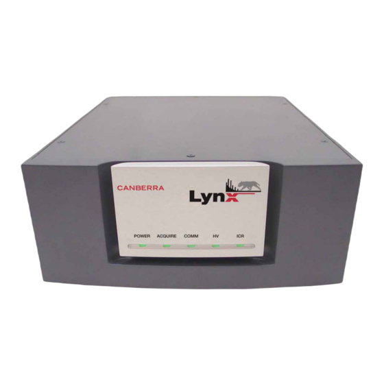
Page 163: Front Panel Indicators
Front Panel Indicators Front Panel Indicators With power applied, you should see some indication(s) on the Lynx's front panel. Figure 107 - Front Panel showing Indicator LEDs POWER Multi-color LED to indicate instrument status. • Green Blinking – Instrument is powered on and in the process of initialization. -
Page 164: Performance
LLD SETTING – 0 to 100%. ULD SETTING – 0 to 100%. INHIBIT MODE – Programmable 0 to 5 ms. LT TRIM – 0 to 1000. PUR GUARD – Programmable guard time 0 to 2.5 times shaping. Lynx™ Digital Signal Analyzer... -
Page 165: Data Acquisition Modes
Performance Data Acquisition Modes The various acquisition modes (dependent on the capabilities of the input) are as fol- lows: • PHA - Pulse Height Analysis • MCS - Multichannel Scaling • MSS - Multispectral Scaling • DLFC - Dual Loss Free Counting •... -
Page 166: Multispectrum Scaling (Mss)
DSP event is stored sequentially in the group memory, one 16-bit word per event. Bit 15 is set to zero. Using TLIST mode, Lynx records all ADC events and time tags associated with each event. When the data is time stamped, the time of arrival of each event is tagged along with the current value of a 32 bit time counter, which can be clocked at 1 MHz, 1 kHz, or 1 Hz. -
Page 167: Mixed Signal Oscilloscope
Mixed Signal Oscilloscope Mixed Signal Oscilloscope The Lynx incorporates an oscilloscope which allows examination of the digital signal reconstructed in time to assist and verify instrument setup, pole/zero optimization and manual Reset Preamp Inhibit adjustments. The operator has the ability to view any one of six analog signals on the same screen as well as any combination or all of eight digital signals. -
Page 168: High Voltage Power Supplies
All outputs are current limited and short-circuit protected. HV INHIBIT INPUT – has two modes. POSITIVE POLARITY – For Canberra preamplifiers. Enable condition (cold detector) is an open circuit or active high = +1.2 V to +24 V; Inhibit condition (warm detector) is –24 V to <+1.2 V or ground. -
Page 169: Hvps Range 2
Physical HVPS Range 2 The following applies to HVPS 2: • OUTPUT – ±1500–5000V at 1 µA max. • RIPPLE – 10 mV P-P. • TEMPERATURE COEFFICIENT – ±50 ppm/ºC. • STABILITY – 0.01%/h, 0.02%/8 h. • ACCURACY – ±2%. •... -
Page 170: Environmental
LYNX-MOUNT KIT – Lynx-19 inch Rack Mount Kit; includes mounting hardware, rack handles and a spacer to allow the physical mounting of one or two Lynx units, oc- cupying 2U in an equipment rack. One kit per each 2U application. -
Page 171: Communications Setup
This manual emphasizes using the Lynx Menu (via web browser), using a conven- tional IP network as the most likely connection scenario. You may configure the Lynx by a variety of methods, but must access the Lynx via one of the default methods in order to make parameter changes within the Lynx. -
Page 172: Quick Ip Setup Summary
'PC-to-Lynx stand-alone system'. Direct Setup: Connect to Lynx with your PC This procedure allows you to connect to and operate the Lynx using your PC and a browser, without other network equipment. Use the red Crossover cable for this. -
Page 173: Dhcp Setup Changes - Optional, For Ip Network Use
Lynx setting from its default fixed IP address to connect using DHCP instead. • The Name of the Lynx must be set as desired. Its default name is “Lynx” and if you only have one Lynx unit you may choose to leave this as is. - Page 174 Name is the network name. Enter a new name for the Lynx (e.g., GeLab; up to 8 contiguous characters maximum) and press Submit. 13. On the Lynx, go to the Network menu item. On the General tab, select the DHCP radio button, and then press Submit to save this change. Once this has been performed, log off the Lynx unit.
-
Page 175: Alternate Setup Connection
• Connect your PC to Lynx using the null modem cable provided with the Lynx. • Set up a RAS account for your Windows PC in order to access the Lynx. See Page 169 for guidance on RAS setup for this wired serial connection. - Page 176 – Enable JavaScript • Tools->Options->Privacy->Cache – Use up to 0 • Tools->Options->Privacy->Cookies – Allow sites to set Cookies – Keep Cookies: "until I close Firefox" • Tools->Options->Privacy->History – Remember visited pages for the last 0 days Lynx™ Digital Signal Analyzer...
-
Page 177: Universal Plug And Play
The Lynx device registers for Universal Plug and Play (UPnP) during start up. This means that once a device (in this case, the Lynx) is running and plugged into your net- work, other computers on the network are informed that it's present and running. - Page 178 UPnP icon will appear in the Windows computer's system tray. Double click on the icon to access “My Network Places”. 10. Double click on the Lynx icon to launch your browser and run the Web-based control application (as described throughout Chapter 4).
-
Page 179: Setting Up A Usb Connection
RNDIS account in order to control the USB connection. USB parameters, including RNDIS, must be set up using some other connection into Lynx before the USB connection method may be used. These steps use the conven- tional IP network access for the Lynx administrator. -
Page 180: Connect Your Pc To The Lynx Via Usb
If/when Windows prompts you to install the driver file, browse the directory in Step 5 above. This might only be required with Windows 2000. Connect the USB cable from your PC to the Lynx. Auto-discovery on your Windows PC should recognize the USB connection to the Lynx. - Page 181 Setting Up a USB Connection 11. Highlight the TCP/IP and select Properties. The Internet Protocol Properties page opens. This sets up the client side (e.g., your PC's end) of the USB connection to some otherwise-unused address. Figure 111 - Setting RNDIS Adapter Properties 12.
- Page 182 • connect the USB cable from your PC to the Lynx, and • select your Internet Browser. • In the URL line, type in 10.0.0.2, and press Enter to connect. You should see the Lynx Log In menu, and you should be able to log in, etc. Lynx™ Digital Signal Analyzer...
-
Page 183: Rs-232 Connections
User Name and Password entries, discussed starting on page 103. • The default System Name for the Lynx, for RAS, is: Lynx The Lynx Name is found at: Lynx Menu | Setup | System | General | Name param- eter, discussed starting on page 123. -
Page 184: Windows Ras Settings For Rs-232 Use
Appendix B - Communications Setup Windows RAS Settings for RS-232 use To connect to the Lynx via RS-232 from your Windows PC, you must create a RAS Direct Serial Connection Phonebook entry in your PC. Right click on the My Network Places desktop icon on your PC's desktop, and then select “Properties”. - Page 185 RS-232 Connections The New Connection Wizard will open (Figure 114). Select its Next button. Figure 114 - The New Connection Wizard Select Set Up an Advanced Connection (Figure 115). Click Next. Figure 115 - Connection Options User’s Manual...
- Page 186 Appendix B - Communications Setup In the next screen (Figure 116), select Connect Directly to Another Computer, then click Next. Figure 116 - Advanced Options In the next screen, select Guest, then click Next. Figure 117 - Select Guest Lynx™ Digital Signal Analyzer...
- Page 187 RS-232 Connections The System Name for the Lynx was set up previously under the Setup | System commands. Enter that name, Lynx (Figure 118) here, then click Next. Figure 118 - Name the Connection In the next screen, select Communications Cable Between Two Computers (Figure 119), then click Next.
- Page 188 Figure 120 - Making the Connection Available 10. Click Finish to exit the Connection Wizard (Figure 121). Figure 121 - Finish to Exit the Connection Wizard Continue onto the next section for more RS-232 connection / RAS account settings. Lynx™ Digital Signal Analyzer...
-
Page 189: Rs-232 Parameter Settings
Connect page for the Connection Name you just set up (see Figure 118) - in this example, the name of this page is Connect Lynx. 11. In the Connect Lynx screen on your PC (see below), enter in the RAS Account Name you entered previously to access the Lynx. - Page 190 14. Scroll down the Maximum Speed list to 57600 (Figure 124). Click OK. Figure 124 - Configuring the Communications Settings 15. Click OK again to return to the Connect Lynx screen (Figure 125). Setup of the RS-232 connection is now complete for the PC side of the connection.
-
Page 191: Using Ras For The Serial (Rs-232) Setup
Lynx Menu | Network | RAS tab | Accounts section, as the User Name and Password entries. You should be connected to the Lynx at this point, and should see the Lynx login page as described in Chapter 4 of this Manual. -
Page 192: Setting Up A Modem Connection
External Modem application. Setting Up RAS for a Modem Connection From your PC, Remote Access Services (RAS) is used to connect your PC to a Lynx that is using a Modem, using an RS-232 connection. - Page 193 RS-232 Connections Select the Create a new connection link in the Network Tasks panel. Figure 126 - Create a new Connection, from My Network Places The New Connection Wizard will open (Figure 127). Select its Next button. Figure 127 - The New Connection Wizard User’s Manual...
- Page 194 Select Connect to the Network at my Workplace (Figure 128) then click Next. Connect to Network at my Workplace Figure 128 - Choose 5. In the next screen, select Dial-up Connection (Figure 129), then click Next. Dial-up Connection Figure 129 - Select Lynx™ Digital Signal Analyzer...
- Page 195 RS-232 Connections 6. The System Name for the Lynx was set up previously under the Setup | System commands. Enter that name, Lynx (Figure 130), then click Next. Figure 130 - Enter a Name for your Connection via Modem 7. Enter the telephone number you'll use to make this connection (Figure 131).
- Page 196 If your computer does not have the “smart card” option, skip this step. Figure 132 - Choose 'No Smart Card' 9. Now set this connection for anyone's use and click Next. Figure 133 - Anyone on this PC can use this RAS connection Lynx™ Digital Signal Analyzer...
-
Page 197: Modem (Rs-232) Configuration
10. Click Finish to exit the Connection Wizard. Figure 134 - Finish RAS Setup for Modem The setup for Lynx connection for a Modem via RS-232 should now be complete. To connect with the Lynx, a dial-up connection using your external modem is used. - Page 198 Figure 135 - Connect to Lynx via Modem Reminder If necessary, these default Lynx settings may be changed at Lynx Menu | Network | RAS tab | Accounts section, as the User Name and Password entries. 12. Press the Properties button to select the modem. The Lynx Modem Properties window will open, as seen in Figure 136.
- Page 199 RS-232 Connections 13. From the General tab, press Configure... and set the Modem options. Click OK to continue. Figure 137 - Set your Modem Configuration options 14. Select the Security tab to setup security. Figure 138 - Security Settings tab on Modem Properties Set up your modem security options as desired.
-
Page 200: Modem Use
After installing the Modem Connection, you should verify modem operation to Lynx by dialing the telephone number for the modem. After the modem answers, it should connect through to the Lynx Login page on your Terminal. Log In to the Lynx menu to verify successful operation of this connection. -
Page 201: Installing Firmware On The Lynx Device
Installing Firmware on the Lynx Device Installing Firmware on the Lynx Device Use these steps only if new Firmware has been required for your Lynx. These steps are abbreviated here, as you will receive appropriate instructions with any updates from our Product Support personnel. - Page 202 Appendix B - Communications Setup For Your Notes Lynx™ Digital Signal Analyzer...
-
Page 203: Shaping Adjustments
Rise Time selection. Independent Adjustment The Lynx DSA allows independent selection of rise time and flat top. A detector with long charge collection times will require a flat top long enough to process all the charge from the detector. -
Page 204: Trade-Offs
For most Ge detector applications, digital trapezoidal shaping provides Gaussian equivalent resolution with half the processing time. Faster processing time means the Lynx DSA provides significantly greater throughput than a traditional analog system with its processing or shaping times set for equivalent resolution. -
Page 205: Rise Time And Flat Top Settings
Gaussian shaping. Rise Time and Flat Top Settings Table B.1 lists the Lynx DSA Rise Time and Flat Top settings which optimize perfor- mance for high throughput/good resolution and optional setting for best resolu- tion/lower throughput when using Germanium Coaxial detectors. - Page 206 However, as the system count rate increases, resolution and through- put may degrade as a result of increased processing time and the effects of pulse pile-up. Table B.2 lists Lynx DSA rise time and flat top settings for other common detectors. Table B.2 Settings for Other Common Detectors Detector...
-
Page 207: Rack-Mounting Your Lynx
- LYNX-MOUNT KIT - is available. One or two Lynx units may be rack-mounted in 2U of a 19-inch equipment rack using one Rack Mount Kit. The rack mount kit includes the rack mount brackets with han- dles, a half-rack filler, and coupling screws. -
Page 208: Rack-Mounting A Single Unit
Using two of the provided socket-head cap screws (SHCS), connect the filler piece to the side of the Lynx main unit. It is not necessary to 'open up' the Lynx main unit. Then, add the brackets to make a complete 2U assembly. - Page 209 Rack-mounting a Single Unit The Lynx unit may be positioned to either side. Verify any clearance or rear-access concerns in your equipment rack when considering placement for a single unit. Figure 140 - Rack Mounting a Single Lynx, showing the half-rack filler piece •...
-
Page 210: Rack-Mounting Two Units
Remove the contents of the Rack Mount kit from its packing material. You will join two Lynx units side-by-side. Of two units, the one positioned to the right as you are facing them must have its cover removed to join the units. - Page 211 Lynx to the left Lynx (as facing them from their front sides). • From inside the right Lynx unit, and using two SHCS in the two upper screw holes (just above the circuit boards), insert and tighten the screws until snug with your Allen wrench.
- Page 212 Appendix D - Rack-mounting Your Lynx For Your Notes Lynx™ Digital Signal Analyzer...
-
Page 213: Installation Considerations
• The use of CE compliant accessories such as fans, UPS, etc. Maintenance Any repairs or maintenance should be performed by a qualified Canberra service rep- resentative. Failure to use exact replacement components, or failure to reassemble the unit as delivered, may affect the unit’s compliance with the specified EU require- ments. - Page 214 Appendix E - Installation Considerations For Your Notes Lynx™ Digital Signal Analyzer...
-
Page 215: Disposal Of This Equipment
The symbol below, also found on your CANBERRA equipment, indicates that this equipment should not be disposed of in unsorted municipal waste. - Page 216 Appendix F - Disposal of This Equipment For Your Notes Lynx™ Digital Signal Analyzer...
-
Page 217: Index
Index 10/100 BASE-TX ....148 Backup ....61,132 10/100T . - Page 218 Digital Storage Oscilloscope ... 5 Connect Lynx ....175 Discriminator ....95 Context-sensitive Help .
- Page 219 Editing GAA ..... . . 35 An MCA Definition ....24 Gain Attenuator .
- Page 220 LTC ..... . 86,87 LYNX ..... . 156 Lynx DSA .
- Page 221 Mac OSX ..... 61 NAID thermistor ....19 Manual Entry .
- Page 222 Pile-Up Rejection Guard ... . . 86 RAS Parameters for Lynx ..169,178 PIPS ......4 RAS Password .
- Page 223 safe operating temperature ... . 17 Take-Over ....67 Sample Changer ....94 Test Pulser - GP I/O3 .
- Page 224 USB Host..... 20 USB PC-to-Lynx ....165 USB Remote .
- Page 225 For Your Notes User’s Manual...
- Page 226 For Your Notes Lynx™ Digital Signal Analyzer...
- Page 227 Canberra (we, us, our) warrants to the customer (you, your) that for a period of ninety (90) days from the date of shipment, software provided by us in connection with equipment manufactured by us shall operate in accordance with applicable specifications when used with equipment manufactured by us and that the media on which the software is provided shall be free from defects.
Need help?
Do you have a question about the Lynx and is the answer not in the manual?
Questions and answers