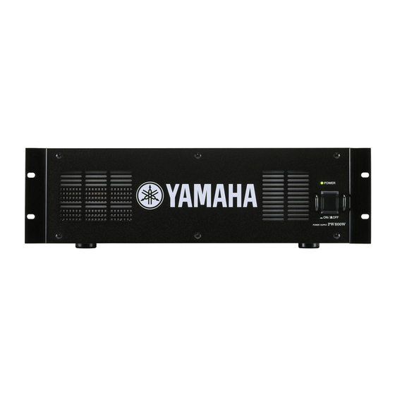
Yamaha PW800W Service Manual
Hide thumbs
Also See for PW800W:
- Owner's manual (10 pages) ,
- Owner's manual (10 pages) ,
- Owner's manual (10 pages)
Table of Contents
Advertisement
Quick Links
PA
011740
200408-オープンプライス
PW800W
SERVICE MANUAL
CONTENTS
(目次)
SPECIFICATIONS
(総合仕様)
PANEL LAYOUT
(パネルレイアウト)
(寸法図)
DIMENSIONS
CIRCUIT BOARD LAYOUT
DISASSEMBLY PROCEDURE
(シート基板図)
CIRCUIT BOARDS
PARTS LIST
OVERALL CONNECTOR CIRCUIT DIAGRAM
(総コネクタ接続回路図)
OVERALL CIRCUIT DIAGRAM
Copyright (c) Yamaha Corporation. All rights reserved.
POWER SUPPLY
................................................... 3
.................................... 4
............................................................ 5
(ユニットレイアウト)
(分解手順)
.............................. 7
....................................... 10
(総回路図)
HAMAMATSU, JAPAN
PW800W
................. 6
1
'04.09
Advertisement
Table of Contents

Summary of Contents for Yamaha PW800W
- Page 1 ............5 (ユニットレイアウト) CIRCUIT BOARD LAYOUT ....6 DISASSEMBLY PROCEDURE (分解手順) ......7 (シート基板図) CIRCUIT BOARDS ........10 PARTS LIST OVERALL CONNECTOR CIRCUIT DIAGRAM (総コネクタ接続回路図) (総回路図) OVERALL CIRCUIT DIAGRAM 011740 HAMAMATSU, JAPAN 200408-オープンプライス Copyright (c) Yamaha Corporation. All rights reserved. ’04.09...
- Page 2 IMPOR TANT NOTICE This manual has been provided for the use of authorized Yamaha Retailers and their service personnel. It has been assumed that basic service procedures inherent to the industry, and more specifically Yamaha Products, are already known and under- stood by the users, and have therefore not been restated.
-
Page 3: Specifications
PW800W (総合仕様) SPECIFICATIONS General Specifications Power Consumption 1000W Dimensions (W x H x D) 480 mm x 142 mm x 384 mm Weight 10 kg Included Accessories Power cord, Cord clamp, Owner's Manual Operating 10°C – 35°C Tempera- ture Range Storage -20°C –... -
Page 4: Panel Layout
PW800W (パネルレイアウト) PANEL LAYOUT Front Panel (フロントパネル) q POWER ON/OFF Switch ([POWER ON/OFF] スイッチ) Rear Panel (リアパネル) w DC OUTPUT Connector (DC OUTPUT コネクター) e DC PARALLEL INPUT Connector (DC PARALLEL INPUT コネクター) r AC IN Connector (AC IN 端子)... - Page 5 PW800W (寸法図) DIMENSIONS Units: mm (単位)...
-
Page 6: Circuit Board Layout
PW800W (ユニットレイアウト) CIRCUIT BOARD LAYOUT Receptacle assembly (レセプタクル Ass'y) <Top view> Power transformer (電源トランス) Power supply unit (AC/DC convertor) Window angle Switch assembly (Power switch) (電源ユニット) (ウインドアングル) (スイ ッチAss'y ( 電源スイ ッチ) ) <Front view>... -
Page 7: Disassembly Procedure
PW800W (分解手順) DISASSEMBLY PROCEDURE Top Cover トップカバー (所要時間 : 約1分) (Time required : About 1 minute) [390]のネジ14本を外し、 トップカバーを外します。 Remove the fourteen (14) screws marked [390]. The (図1) top cover can then be removed. (Fig. 1) Power Supply Unit (Time required : About 2 minutes) 電源ユニット... - Page 8 PW800W [390] Top cover (トップカバー) [390] Heat sink [230A] [225] (ヒートシンク DS) Window angle (ウインドアングル) [310] Holder ( ヒートシンク取付金具) [310] Power supply unit [310] (電源ユニット) [200] [290] [310] [200] [240] [300] [240] [310] SW power angle [317] (SW 電源取付け金具) Power transformer (電源トランス)...
- Page 9 PW800W Rear Fan Motor リアDCファンモーター (所要時間 : 約2分) (Time required : About 2 minutes) 9-1. トップカバーを外します。 ( 1項参照) 9-1. Remove the top cover. (See procedure 1) 9-2. [120B]のネジ4本を外し、 DCファンモーター (L) 、 9-2. Remove the four (4) screws marked [120B]. The fan ファンガイド2個、...
-
Page 10: Circuit Boards (シート基板図
PW800W CIRCUIT BOARDS (シート基板図) DC Circuit Board to DC OUTPUT to DC PARALLEL INPUT to Power Supply Unit-CN2 AC Circuit Board to Power Transformer to Power Supply Unit-CN1 (Primary) Component side to AC Inlet (部品側) to Power Switch 2NAP-WB75820-01... - Page 11 PW800W to Power Supply Unit-CN2 to DC PARALLEL INPUT to DC OUTPUT Component side to FAN (Rear R) to FAN (Rear L) to Power Transformer (部品側) (Secondary) to FAN (Front) LED Circuit Board Component side (部品側) POWER 2NAP-WB75820-01...
-
Page 12: Power Supply
PW800W POWER SUPPLY PW800W PARTS LIST (目次) CONTENTS OVERALL ASSEMBLY ..........2 (総組立) ELECTRICAL PARTS ........5~6 (電気部品) Notes : DESTINATION ABBREVIATIONS A : Australian model M : South African model B : British model O : Chinese model C : Canadian model... - Page 13 150a...
- Page 14 Top view 520 510 Bottom side ↑ Bottom side ↑ (ボトム側) (ボトム側)...
- Page 15 PW800W PART NO. DESCRIPTION 部 品 名 REMARKS REF NO. RANK OVERALL ASSEMBLY 総 組 立 PW800W Overall Assembly (WB67810) 総 組 立 Bottom WB678400 ボ ト ム 加 工 上 り CB806590 Leg Black ア ン プ レ ッ...
-
Page 16: Electrical Parts(電気部品
PW800W ELECTRICAL PARTS(電気部品) PART NO. DESCRIPTION 部 品 名 REMARKS REF NO. RANK 電 気 部 品 ELECTRICAL PARTS PW800W WB788700 Circuit Board AC (PWCOM) A C シ ー ト (WB75820)(X4589B0) WB788800 Circuit Board DC (PWCOM) D C シ ー... - Page 17 PW800W PART NO. DESCRIPTION 部 品 名 REMARKS REF NO. RANK 酸 化 金 属 被 膜 抵 抗 VC748400 Metal Oxide Film Resistor 2.2K 1W J カ ー ボ ン 抵 抗 HF757100 Carbon Resistor 10.0K 1/4 J HF757100 Carbon Resistor 10.0K 1/4 J...
- Page 18 PW800W OVERALL CONNECTOR CIRCUIT DIAGRAM (PW800W) Circuit Board name CN number PIN number Circuit Board name CN number PIN number (シート名) (CN番号) (ピン番号) (シート名) (CN番号) (ピン番号) AC/AD CONVERTOR AC Circuit Board (POWER SUPPLY) [POWER [AC IN] ON/OFF] AC INLET POWER...
- Page 19 PW800W OVERALL CIRCUIT DIAGRAM (PW800W) POWER SUPPLY UNIT CONNECTOR Voltage Adjust AC INLET POWER SUPPLY UNIT (AC/DC CONVERTOR) REGULATOR ※ POWER SWITCH CN4: N.C (Rear R) 10EDA40-TA2B5 PQ1CG21H2FZ(XY455A00) CN5: N.C (WB880800) REGULATOR DC: IC1 DIODE DC: D1-3, 5, 6, 8...
-
Page 20: Parts List
PSL120 POWER SUPPLY LINK CABLE PSL120 PARTS LIST Notes : DESTINATION ABBREVIATIONS A : Australian model M : South African model B : British model O : Chinese model C : Canadian model Q : South-east Asia model D : German model T : Taiwan model E : European model U : U.S.A. - Page 21 PSL120 PW800W PW800W PSL120 PARTS LIST (パーツリスト) 部 品 名 PART NO. DESCRIPTION REMARKS REF NO. RANK COMPLETE ASSEMBLY 同 梱 品 セ ッ ト PSL120 Complete Assembly 同 梱 品 セ ッ ト (WD19450) Complete Assembly 同 梱 品...


Need help?
Do you have a question about the PW800W and is the answer not in the manual?
Questions and answers