DUROMAX XP12000EH User Manual
Hide thumbs
Also See for XP12000EH:
- Manual (68 pages) ,
- User manual (84 pages) ,
- Service manual (54 pages)
Table of Contents
Advertisement
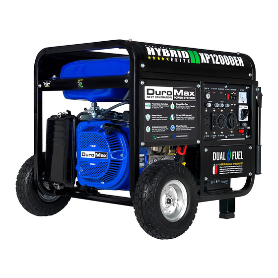
*Gasoline & Propane Tank Not Included
XP12000EH GENERATOR
User Manual
REV: XP12000EH-07032017
5798 Ontario Mills Pkwy
Ontario, CA 91764 USA
This manual provides information regarding the operation
www.duromaxpowerequipment.com
and maintenance of these products. We have made every
effort to ensure the accuracy of the information in this
Call our Customer Care Team Toll Free 8-5pm PST Mon-Fri
manual. We reserve the right to change this product at
800-629-3325
any time without prior notice.
Advertisement
Table of Contents
Troubleshooting

Related Manuals for DUROMAX XP12000EH


Summary of Contents for DUROMAX XP12000EH
- Page 1 *Gasoline & Propane Tank Not Included XP12000EH GENERATOR User Manual REV: XP12000EH-07032017 5798 Ontario Mills Pkwy Ontario, CA 91764 USA This manual provides information regarding the operation www.duromaxpowerequipment.com and maintenance of these products. We have made every effort to ensure the accuracy of the information in this Call our Customer Care Team Toll Free 8-5pm PST Mon-Fri manual.
-
Page 3: Table Of Contents
CONTENTS Introduction Introduction ........................6 General Safety Procedures ................... 7 Quick Start Guide (Gasoline) ..................10 Quick Start Guide (Propane) ..................12 Generator Components ....................14 Package Contents ......................16 Generator Setup Shipping Braces ......................18 Wheel Kit Installation ....................19 Adding Oil ........................ - Page 4 CONTENTS Maintenance and Care Maintenance Schedule ....................40 Maintenance Log ......................41 Checking the Oil ......................42 Changing the Oil ......................43 Cleaning the Air Filter ....................44 Spark Plug Maintenance ....................46 Emptying the Gas Tank ....................48 Cleaning the Fuel Filter Cup ..................50 Storage and Transportation ..................
-
Page 6: Introduction
INTRODUCTION DuroMax has cemented its reputation as one of the markets leading power equipment companies who are headquartered in the US. All of our products are manufactured to the strictest guidelines and go through countless testing in all phases of production. -
Page 7: General Safety Procedures
GENERAL SAFETY PROCEDURES SAFETY ALERT SYMBOL The safety alert symbol is used with one of the safety words (DANGER, CAUTION, or WARNING) to alert you of hazards. Please pay attention to these hazard notices both in this manual and on the generator. Please familiarize yourself with the following safety symbols and words: DANGER: Indicates a hazard that will result in serious injury or death if instructions are not ●... - Page 8 GENERAL SAFETY PROCEDURES WARNING: This generator may emit highly flammable and explosive gasoline vapors, which can cause severe burns or even death. A nearby open flame can lead to an explosion even if not directly in contact with gas. Do not operate near an open flame. ●...
- Page 9 GENERAL SAFETY PROCEDURES In addition to the above safety notices, please familiarize yourself with the safety and hazard markings on the generator.
-
Page 10: Quick Start Guide (Gasoline)
QUICK START GUIDE (GASOLINE) Remove shipping braces The shipping braces prevent engine movement during shipment. Flip the generator over and remove the brightly colored brace between the motor and the frame, and the wood brace under the generator. Add oil The oil fill cap is located on the lower engine block to the right of the recoil start housing. - Page 11 Close choke The choke lever is located above the air filter to the right of the recoil start. Slide the lever to the left to cut the air supply and allow more gas into the engine to start. Start generator The key switch is located on the left side of the front power panel.
-
Page 12: Quick Start Guide (Propane)
QUICK START GUIDE (PROPANE) Remove shipping braces The shipping braces prevent engine movement during shipment. Flip the generator over and remove the brightly colored brace between the motor and the frame, and the wood brace under the generator. Add oil The oil fill cap is located on the lower engine block to the right of the recoil start housing. - Page 13 Connect propane tank The propane hose is located on the left side of the regulator, below the OHV valve cover. Screw the open ACME nut connection to your propane tank and turn the tank on. Release propane pressure The propane regulator / decompression valve is located on the frame of the generator below the OHV valve cover.
-
Page 14: Generator Components
GENERATOR COMPONENTS 22. 120/240v 4-Prong 8. 120v 3-Prong Receptacle Receptacle 21. 120V 3 Prong Twist Lock 2. Choke Lever 23. Auto Throttle 5. Circuit Breaker 10. Volt Meter 1. Power Boost 16. Fuel Valve 7. Ground Terminal 1. Air Filter 11. - Page 15 15. Fuel Filter Cup 3. Fuel Gauge 4. Fuel Cap 17. Spark Plug 18. Muffler 20. Pressure Release Valve 19. Propane Connector 12. Oil Fill and Dipstick - Use to add or check the oil. 13. Engine Switch – 3 Position Switch to “Start”, “Run”, or turn “Off” the generator. 14.
-
Page 16: Package Contents
PACKAGE CONTENTS Your generator comes with the items listed below. Please check to see that all of the following items are included with your generator. Double Sided Spanner Spark Plug Wrench Screw Driver Phillips and slot blade Assorted wrenches used in Used in spark plug screwdriver used for generator generator maintenance and... -
Page 17: Generator Setup
GENERATOR SETUP Proper setup of your generator will get you going as soon as possible while making sure you and your equipment are safe and cared for. -
Page 18: Shipping Braces
GENERATOR SETUP Step 1 - Remove Shipping Braces Unpack Remove the generator from the box. Place the largest piece of packing foam on a flat surface. Flip the generator upside down on the pad. CAUTION: NEVER Attempt this if you have put fuel or oil in the generator. -
Page 19: Wheel Kit Installation
Step 2 - Wheel Kit Installation (Optional) Install support legs Secure the support legs to the frame with provided bolts and lock nuts. Install wheels Insert wheel bolt through frame and secure with provided nut. Slide one wheel over each axle end and secure with the provided retaining pins. -
Page 20: Adding Oil
. You must add the proper amount of oil before operating the generator for the first time. This amount is equal to the oil capacity of the engine crankcase: Model Number XP12000EH Engine Oil Capacity 37 fl. oz (1.1L) WARNING: Do not apply engine oils with additives or 2-stroke gasoline engine oils. They don’t have enough lubrication, and may shorten the engine’s service life. -
Page 21: Adding Gasoline
Gas can age in the tank and make it hard to start up ● the generator in the future. Never store generator for extended periods of time ● with fuel in the tank. Model Number XP12000EH Gas Tank Capacity 7.9 US Gallons (30L) -
Page 22: Grounding The Generator
GENERATOR SETUP (CONTINUED) Step 5 - Grounding the Generator Attach grounding wire Ground the generator by tightening the grounding nut against a grounding wire. Connect the other end to a copper or brass grounding rod that’s driven into the earth. A generally acceptable grounding wire is a No. -
Page 23: Starting The Generator
STARTING THE GENERATOR If this is not your first time using the generator there are still steps you should take to prepare it for operation each time you use it. IMPORTANT: At this point you should be familiar with the procedures described in the first portion of this section entitled “GENERATOR SETUP”... -
Page 24: Checking The Oil
BEFORE YOU START YOUR GENERATOR Step 1 - Check the oil Check the oil The generator is equipped with an automatic shutoff to protect it from damage due to low oil. Nonetheless, you should check the oil level of the engine before each use to ensure that the engine crankcase has a sufficient amount. -
Page 25: Check The Gas Level
Step 2 - Check the gas level Check Fuel Level Before starting the generator, check to see that there is sufficient gasoline in the fuel tank. The fuel gauge on top of the tank will give a rough estimate of the gasoline level. The gauge will appear white then fill red as the tank is filled. -
Page 26: Starting The Generator Using Gasoline
STARTING THE GENERATOR Starting the Generator Using Gasoline Shut breaker off The breaker is located on the right side of the front power panel. Flip the breaker down to prevent accidental load when starting the generator. Turn gas valve on The gas valve is located above the recoil start on the bottom of the fuel tank. - Page 27 Turn engine switch to ON When the engine starts, allow the engine switch to return to the ON position. Open choke Push the choke to the OPEN position as the engine warms up. CAUTION: LPG must be shut off when using gasoline! CAUTION: Gasoline must be shut off when using LPG! CAUTION: Disconnect all electrical loads from the generator before attempting to start!
-
Page 28: Starting The Generator Using Propane
STARTING THE GENERATOR (CONTINUED) Starting the Generator Using Propane Turn breaker off The breaker is located on the right side of the front power panel. Flip the breaker down to prevent accidental load when starting the generator. Turn gas valve off The gas valve is located above the recoil start on the bottom of the fuel tank. - Page 29 Release propane pressure The propane regulator / decompression valve is located on the frame of the generator below the OHV valve cover. Press the button in the center down 3-5 times for one second to clear the air from the lines and fill the carburetor. Adjust choke The choke lever is located above the air filter to the right of the recoil start.
- Page 30 STARTING THE GENERATOR (CONTINUED) Starting the Generator Using Propane WARNING: WHEN USING THE GENERATOR WITH LPG, MAKE SURE THERE IS NO POSSIBLE IGNITION SOURCE CLOSE TO THE GENERATOR. 1. Before using, make sure all of the LPG connectors and hoses are well connected and sealed.
-
Page 31: Using The Generator
USING THE GENERATOR If this is not your first time using the generator there are still steps you should take to prepare it for operation each time you use it. IMPORTANT: At this point you should be familiar with the procedures described in the first portion of this section entitled “GENERATOR SETUP”... -
Page 32: Ac Usage
USING THE GENERATOR AC Usage ● You may connect electrical devices running on AC current according to their wattage requirements. The chart below shows the rated and surge wattage of your generator according to its model ● number. ● The rated wattage corresponds to the maximum wattage the generator can output on a continuous basis. - Page 33 Tool or Appliance Rated (Running) Watts Additional Surge Watts Electric water heater (40 gal) 4000 Hot plate 2500 Radial arm saw 2000 2000 Electric Stove 1500 Circular Saw 1500 1500 Air compressor (1 HP) 1500 3000 Window air conditioner 1200 1800 Miter saw 1200...
-
Page 34: Connecting A Load To The Generator
USING THE GENERATOR (CONTINUED) Connecting a load to the generator NOTE: Be sure to attach devices to the correct receptacle (outlet). 120v devices can be directly connected to the 120v ONLY receptacles. ● 120v devices can be connected to the 120/240v receptacle using an appropriate adapter. ●... -
Page 35: Voltage Selector Switch
Voltage Selector Switch This generator features Power Boost Technology, which gives the user POWER BOOST the ability to double the power in the generator for more heavy duty applications. The voltage selector switches the dual 120v AC windings of the generator TECHNOLOGY to produce “120V ONLY”... -
Page 36: Dc Usage
USING THE GENERATOR (CONTINUED) DC Usage CAUTION: The DC receptacle is for recharging 12 Volt automotive-type batteries only. Do not connect any other device to this receptacle. CAUTION: Never try to jump start a car with your generator. Connect the battery Connect one charging wire to the positive terminal on the battery and the other charging wire to the negative terminal on the battery. - Page 37 Connect negative receptacle Carefully connect the free end of the negative wire to the negative receptacle on the generator. Disconnecting When disconnecting, always disconnect the wires from the generator first to avoid a spark. DANGER - Stored batteries emit highly explosive hydrogen gas when charged. Batteries also contain acid, which can cause severe chemical burns.
-
Page 39: Maintenance And Care
MAINTENANCE AND CARE Proper maintenance and storage of your generator is essential to ensure trouble free use of your generator when you need it. By following the maintenance and care requirements, you can keep your generator running smooth and efficient for years to come. -
Page 40: Maintenance Schedule
MAINTENANCE AND CARE Proper routine maintenance of your generator is essential for safe, economical, and trouble-free operation. It will also help reduce air pollution. WARNING: Improper maintenance, or failure to correct a problem before operation, can cause a malfunction in which you can be seriously injured or killed. Always follow the inspection and maintenance recommendations and schedules in this instruction manual. -
Page 41: Maintenance Log
MAINTENANCE LOG Date Generator Hours Maintenance Performed... -
Page 42: Checking The Oil
MAINTENANCE AND CARE (CONTINUED) Checking the oil Check the oil The generator is equipped with an automatic shutoff to protect it from damage due to low oil. Nonetheless, you should check the oil level of the engine before each use to ensure that the engine crankcase has a sufficient amount. -
Page 43: Changing The Oil
Changing the oil Worn out or dirty oil does not cool the generator properly and can lead to catastrophic engine damage. In addition to regular oil changes, it is necessary to drain the oil from the crankcase if it has become contaminated with water or dirt. -
Page 44: Cleaning The Air Filter
MAINTENANCE AND CARE (CONTINUED) Cleaning the air filter Routine maintenance of the air cleaner helps maintain proper airflow to the carburetor. Check that the air cleaner is free of excessive dirt after every use. Note: Improper maintenance may cause less air to enter the engine or dirty air to enter the engine causing overheating and engine wear. - Page 45 Wash filter element Wash the sponge-like elements in household dish detergent and warm water. Dry filter element Allow the elements to dry completely. Add engine oil to elements Soak the dry elements in a small amount of engine oil. Ring out any excess oil.
-
Page 46: Spark Plug Maintenance
MAINTENANCE AND CARE (CONTINUED) Spark Plug Maintenance The spark plug is important for proper engine operation. A good spark plug should be intact, free of deposits, and properly gapped. Improper maintenance may cause reduced fuel economy, misfires, trouble starting, or damage to the spark plug threads. - Page 47 Measure plug gap Measure the plug gap with a gauge. The gap should be 0.7-0.8 mm (0.028-0.031 in). Clean and re-gap If you are re-using the spark plug, use a wire brush to clean any dirt from around the spark plug base and then re-gap the spark plug.
-
Page 48: Emptying The Gas Tank
MAINTENANCE AND CARE (CONTINUED) Emptying the Gas Tank Before storing your generator for extended periods of time, you should drain your generator of gasoline. CAUTION: Do not store fuel from one season to another. Gasoline sold at the pump today contains additives such as ethanol that even when stored properly may damage the fuel system components. - Page 49 Drain gas from generator With a receptacle underneath the generator to catch the gas, turn the fuel valve to the “ON” position. Drain all the gas from the generator. Shut fuel valve off Turn the fuel valve to the “OFF” position. Replace fuel filter cup Reinstall the fuel filter cup.
-
Page 50: Cleaning The Fuel Filter Cup
MAINTENANCE AND CARE (CONTINUED) Cleaning the fuel filter cup Shut fuel valve off Turn the fuel valve to the “OFF” position. Remove fuel filter cup Unscrew the fuel filter cup from the fuel valve using a wrench. Turn the valve towards you to unscrew Clean filter cup Clean the cup of all sediment using a rag or brush. -
Page 51: Storage And Transportation
Storage and Transportation CAUTION: Never place any type of storage cover on the generator while it is still hot. When transporting your generator: Empty the gas tank (see “Emptying the Gas Tank” in the “Maintenance” section). ● Disconnect the spark plug. ●... -
Page 52: Specifications
SPECIFICATIONS AC Rated Wattage (Gasoline) 9500W AC Rated Wattage (Propane) 8075W AC Surge Wattage (Gasoline) 12000W AC Surge Wattage (Propane) 10200W AC Rated Voltage 120/240V AC Rated Frequency 60 Hz AC Phase Single DC Voltage DC Amperage 8.3A Dimensions LENGTH 28in. -
Page 53: Troubleshooting
TROUBLESHOOTING This section of the manual is to help you troubleshoot problems with your generator. -
Page 54: Basic Troubleshooting
TROUBLESHOOTING Mode Description Engine Switch is “Off” Set engine switch to “run” Fuel Valve is “Closed” Turn fuel valve to “open” Choke is open Close the choke Engine is out of fuel Add fuel Engine will not start Fuel is old or contaminated Change fuel Spark Plug is dirty Clean spark plug... -
Page 55: Changing / Inspecting The Carbon Brushes
Changing / Inspecting the Carbon Brushes The carbon brushes in conjunction with the AVR regulates power from the generator. The carbon brushes are wearable parts and should be inspected every 250 running hours. Remove generator cover Remove the 2 bolts of the generator cover then pull the cover off the generator. - Page 56 TROUBLESHOOTING (CONTINUED) Changing / Inspecting the Carbon Brushes (Cont.) Install new brush Install new carbon brush with bolt. Connect AVR wires Insert and connect the 2 wires from the AVR, be sure to connect + and – correctly. Replace generator cover Replace the back cover of the generator and secure with the 2 bolts.
-
Page 57: Changing / Inspecting The Avr
Changing / Inspecting the AVR The carbon brushes in conjunction with the AVR regulates power from the generator. If the generator is overheated or overloaded, the AVR may be damaged and require replacement. Remove generator cover Remove the 2 bolts of the generator cover then pull the cover off the generator. - Page 58 TROUBLESHOOTING (CONTINUED) Changing / Inspecting the AVR (Continued) Disconnect wires from brush Remove the 2 wires from the AVR on the carbon brush. Install new AVR Install the new AVR with the 2 bolts. Reconnect wires to brush Reconnect the wire clip. Reconnect the AVR wire clip Insert and connect the 2 wires from the AVR, be sure to connect + and –...
- Page 59 Replace generator cover Replace the back cover of the generator and secure with the 2 bolts.
- Page 60 WIRING DIAGRAM...
-
Page 62: Warranty
Warranty Limitations DuroMax/DuroStar Power Equipment does not claim or hold any obligation to loss of time, freight charges, use of product, or any incidental damages from the use of this product. THIS WARRANTY IS IN LIEU OF ALL OTHER WARRANTIES, EXPRESSED OR IMPLIED. - Page 63 Equipment cannot deny warranty solely for the lack of receipts or your failure to ensure the performance of all scheduled maintenance. As the small off-road engine owner, you should however be aware that the DuroMax Power ● Equipment may deny you warranty coverage if your small off-road engine or a part has failed due to abuse, neglect, or improper maintenance or unapproved modifications.
- Page 64 WARRANTY (CONTINUED) 2. Any warranted part that is scheduled only for regular inspection in the Owner’s Manual must be warranted for the warranty period stated above. A statement in such written instructions to the effect of “repair or replace as necessary” will not reduce the period of warranty coverage. Any such part repaired or replaced under warranty must be warranted for the remaining warranty period.
- Page 65 *Note: The parts list for equipment less than or equal to 80 cc only includes the fuel tank. **Note: As they relate to the evaporative emission control system. DuroMax Power Equipment will furnish with each new engine written instructions for the maintenance and use of the engine by the owner.
-
Page 66: Contact Information
CUSTOMER SERVICE Duromax Power Equipment is comitted to ensuring that our products perform when they need to. Our generators are your lifeline in the event of an emergency. Should you have any problems, please contact our customer service department: DUROMAX POWER EQUIPMENT... - Page 68 5798 Ontario Mills Parkway Ontario, CA 91764 United States 800-629-3325...
Need help?
Do you have a question about the XP12000EH and is the answer not in the manual?
Questions and answers
The connection size for the lp male connector on this generator,